Administering the Switch
This chapter describes administrative tasks typically performed only after initially configuring the switch or after recovery procedures.
This chapter includes these sections:

This chapter describes administrative tasks typically performed only after initially configuring the switch or after recovery procedures.
This section contains the following topic:
Arista Networks features switches with high-density, non-blocking Ethernet ports controlled through an extensible, Linux-based, modular network operating system. The intended audience for this manual is network administrators who configure Arista switches. A working knowledge of network administration is assumed.
This guide may not describe the features added in the most recent EOS version. For information on undocumented features, consult the TOI documents here: https://www.arista.com/en/support/toi.
A list of Arista switches and detailed information about each is available here: https://www.arista.com/en/products.
Recently released switches may not appear in the list but can be found in the most recent Release Notes (found under Active Releases here: https://www.arista.com/en/support/software-download).
Portions of Arista Networks software are covered by open-source licenses, including the GNU General Public License (GNU GPL).
See https://www.arista.com/en/support/product-documentation/gpl.
The configuration tasks required to deploy CloudVision, CVX, and CVP are in the CloudVision Configuration Guide. The latest version is available here: https://www.arista.com/en/cg-cv/.
For the complete supported features list in the latest EOS release, see https://www.arista.com/en/support/product-documentation/supported-features.
For details on a specific release, see the Release Notes (found under Active Releases here: https://www.arista.com/en/support/software-download).
The command-line interface (CLI) provides a tool for controlling the switch and displaying information about status and configuration. This chapter describes the use of the CLI.
The following figure displays the EOS CLI in a Secure Shell connection.
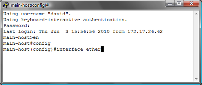
The command abbreviation con does not execute a command in Privileged EXEC mode because the names of two commands begin with these letters: configure and connect.
switch# con
% Ambiguous command
The command abbreviation conf executes configure in Privileged EXEC mode because no other command name begins with conf.
switch# conf
switch(config)#
The alias command creates an alias for a CLI command. Entering the alias in the CLI executes the corresponding command.
Example
switch(config)# alias srie show running-config interface ethernet 1-5
switch(config)# srie
interface Ethernet1
   switchport access vlan 33
   storm-control broadcast level 1
   spanning-tree portfast
   spanning-tree bpduguard enable
interface Ethernet2
   switchport access vlan 33
   spanning-tree portfast
interface Ethernet3
   switchport access vlan 33
   spanning-tree portfast
   spanning-tree bpduguard enable
interface Ethernet4
interface Ethernet5
shutdownThe show history command in Privileged EXEC mode displays the history buffer contents.
switch# show history
  en
  config
  exit
show historyTo display all commands available at this level, type a question mark (?):
switch# ?
  clear       Reset functions
  connect     Open a terminal connection
  default     Set a command to its defaults
  disable     Turn off privileged commands
  enable      Turn on privileged commands
  exit        Exit from the EXEC
  logout      Exit from the EXEC
  no          Negate a command or set its defaults
  ping        Send echo messages
  show        Show running system information
  ssh         Open ssh connection
  tcpdump     Monitor packets with tcpdump
  telnet      Open a telnet connection
  terminal    Configure the terminal
  traceroute  Trace route to destination
  watch       Execute a command repeatedly
  who         Display information about terminal lines
  zerotouch   ZeroTouch configuration
ping/traceroute fails to check uSID
reachability in SRv6 due to an ICMPv6 checksum mismatch. This occurs because
the destination address (DA) changes as the packet traverses the Segment
List, but calculates the initial checksum on the original DA. To correctly
verify reachability, you must use the srv6 ping
command.To display a list of commands beginning with a specific character sequence, type the sequence followed by a question mark.
switch# di?
diff  dir  disable
To display the command keywords or arguments, type a question mark as an argument.
switch# ping ?
WORD  Ping destination address or hostname
ip    IPv4 echo
ipv6  IPv6 echo
mpls  Send echo messages for LSP
vrf   Ping in a VRF
The switch accepts an address-mask or CIDR notation (address-prefix) in commands that require an IP address and mask. For example, EOS processes these commands identically:
switch(config)# ip route 0.0.0.0 255.255.255.255 10.1.1.254
switch(config)# ip route 0.0.0.0/32 10.1.1.254
The switch accepts an address-wildcard or CIDR notation in commands requiring an IP address and wildcard. Wildcards use zeros to mask portions of the IP address and are found in some protocol configuration statements, including OSPF. The switch processes these commands identically:
switch(config-router-ospf)# network 10.255.255.1 0.0.0.255 area 15
switch(config-router-ospf)# network 10.255.255.1/24 area 15A regular expression uses a search pattern composed of symbols, letters and numbers. Some CLI parameters are defined as regular expressions for specifying more expressive search criteria. The switch uses regular expression pattern matching in several BGP commands.
The functionality of a regular expression for an AS-Path varies based on BGP regex
asn and string mode configurations in the ip as-path
regex-mode command.
The following tables describe the behavior of special characters in asn and
string modes respectively.
| Special Characters | Characters Names | Description | Examples |
|---|---|---|---|
| . | Period | Matches any AS number. | ‘.’
matches ‘200’. ‘10.20’ matches ‘10 30 20’, but does not match ‘10 20’. |
| ^ | Caret | Matches the specified expression at the beginning of an input string. Also used to exclude expressions in brackets while matching. | ‘^123’
matches ‘123’, ‘123 456’, ‘123 456 789’, and so on; but does not match
‘1234’. ‘[^12]’ matches ‘1’, ‘2’, ‘3’, and so on; but does not match ‘12’. |
| * | Asterisk | Matches an entire AS number that appears either zero or more times. | ‘200_100*_300’ matches '200 300', ‘200 100 300’, ‘200 100 100 300’, and
so on. '^100*$' matches empty AS path, '100', '100 100', '100 100 100', and so on. |
| + | Plus sign | Matches an entire AS number appearing either one or more times. | ‘10_20+_30’ matches ‘10 20 30’, ‘10 20 20 30’ and so on; but does not match ‘10 200 30’. |
| $ | Dollar sign | Matches the specified expression at the end of an input string. | ‘1_2_3$’ matches ‘1 2 3’, but does not match ‘1 2 3 4’. |
| [] | Brackets | Matches either an AS number, or a range of AS numbers separated by a hyphen. | ‘[10_20_30-39]’ matches ‘10’, ‘20’, ‘30’, ‘31’,...’39’. |
| ? | Question mark | Matches either zero or one occurrence of the pattern but the previous operand or entire AS number may appear zero or one time. | ‘100_200?’ matches ‘100’ and ‘100 200’. ‘100_200?$’ does not match with ‘100 20’. |
| | | Pipe | Matches the specified AS number on either side of the vertical bar. | ‘6400|6500’ matches either ‘6400’ or ‘6500’. |
| ( ) | Parenthesis | Nests specified AS numbers for matching. | ‘^(100(200|300))$’ matches either ‘100 200’ or ‘100
300’. ‘^100_200|300_400$’ matches AS path either “100 200” or “300 400”. |
| _ | Underscore | Matches specified AS numbers that are converted into AS number delimiters. | ‘_123_456_’ matches ‘123 456’. ‘_333_444_’ matches ‘111 222 {333 444}’. |
| Special Characters | Characters Names | Description | Examples |
|---|---|---|---|
| . | Period | Matches any single character. | ‘1.2’ matches ‘102’. |
| ^ | Caret | Matches the specified expression at the beginning of an input string. | ‘^123’ matches ‘123’, ‘1234’, ‘12345’, and so on. It also matches ‘123 456’, ‘123 456 789’, and so on. |
| * | Asterisk | Matches either zero or more sequences of the expression preceding the asterisk. | '^5*$' matches an empty AS path, '5', '55', '555', and so on. |
| + | Plus sign | Matches either one or more sequences of the expression preceding the plus sign. | ‘5+’ matches to ‘5’, ‘55’, ‘555’, and so on. |
| $ | Dollar sign | Matches the expression at the end of an input string. | ‘123$’ matches ‘123’, but does not match ‘1234’. |
| [] | Brackets | Matches either characters or a range of characters separated by a hyphen, within left and right brackets. | ‘[025-7]’ matches ‘0’, ‘2’, and digits from ‘5’ to ‘7’; but does not match digits from ‘1’, ‘3’, ‘4’, ‘8’, and ‘9’. |
| ? | Question mark | Matches either zero or one occurrence of the pattern. | '12?3' matches '13' and '123'. |
| | | Pipe | Matches either one of the expressions or expression patterns on either side of the vertical bar. | ‘14(36|75)12’ matches either ‘143612’ or ‘147512’; but does not match ‘1412’, ‘14367512’, ‘14363612’ or ‘14757512’. |
| ( ) | Parenthesis | Nests specified expressions for matching. | ‘(17)*’ matches any number of the two-character string ‘17’. |
| _ | Underscore | For AS-Path regex, '_' matches curly brackets '{}', the beginning of input string, the end of input string, or space. | ‘_1300_’ matches ‘100 {1300 1400}’, ‘100 1300 200’, and so on. |
| {} | Braces | Matches repetitions of the previous expression with the number of repetitions provided in braces. | '10{2,3}' matches '100' and '1000'. |
| \ | Backslash | Matches the character following the backslash and special characters. | ‘\(42’ matches ‘(42’. |
Precede the question mark (?) with Ctrl+V sequence to prevent it from interpretation as a help command.
The schedule command facilitates the periodic execution of the specified CLI command. Command parameters configure the time to start script execution, the interval between consecutive execution instances, the maximum time to execute the script, and the maximum number of file logs to create.
The schedule config command sets configuration parameters with the CLI scheduler.
The show schedule command lists the commands currently scheduled for periodic execution and displays the summary of the specified scheduled command.
This command schedules the execution of a script once every 720 minutes (12 hours) and terminates the script execution if it exceeds 40 minutes. If max-log-files set to zero, the script output does not log any information..
switch# schedule ms_1 interval 720 timeout 40 max-log-files 0 command bash /mnt/flash/myscript.sh switch(config)# show schedule ms_1
CLI command "bash /mnt/flash/myscript.sh" is scheduled next at "03:54:54 07/15/2025", interval is 720 minutes
Timeout is 40 minutes
Maximum of 0 log files will be stored
Verbose logging is off
No log files are stored in flash:/schedule/ms_1/This command saves the running configuration contents to a log file every 60 minutes (1 hour) and terminates the script execution if it exceeds 30 minutes and creates up to 24 log files.
switch(config)# schedule backup-test interval 60 max-log-files 24 command show running-config This command allows the switch to concurrently execute up to 2 scheduled commands.
switch(config)# schedule config max-concurrent-jobs 2This command lists the commands scheduled for periodic execution.
switch(config)# schedule config max-concurrent-jobs 3
switch(config)# show schedule summary
Maximum concurrent jobs  3
Prepend host name to logfile: No
Name            At time      Last    Interval   Timeout   Max     Logfile Location               Status
                             time     (mins)    (mins)    log
                                                         files
------------- ------------- ------- ---------- -------- -------- ------------------------------- ------
tech-support      now        00:29      60        30      100     flash:schedule/tech-support/   Success
thelp           12:02:00     00:02      60        40      100     flash:schedule/thelp/          Fail
06/05/2018Event handlers execute a Linux Bash shell command in response to a specific system event. An event handler consists of a Bash command, a trigger and a delay; when the trigger event occurs, the action is scheduled to run after delay seconds.
To change the delay period between the trigger and the action, use the delay command.
To execute more than one Bash command in response to a trigger, create a script containing the desired commands and enter the file path to the script as the argument of the action bash command.
To display information about all event handlers or about a specific event handler, use the show event-handler command.
The no event-handler command deletes an event handler.
switch(config)# event-handler eth_4
switch(config-event-eth_4)# action bash email This email address is being protected from spambots. You need JavaScript enabled to view it. -s "Et4 $OPERSTATE"
switch(config-event-eth_4)# trigger on-intf ethernet 4 operstatus
switch(config-event-eth_4)# delay 60
switch(config-event-eth_4)# exit
switch(config)#The above handler uses the $OPERSTATE variable to include the current operational state, linkup or linkdown, in the subject of the email. Note that the action only function if you configured email on the switch.
switch(config)# event-handler onStartup
switch(config-event-onStartup)# action bash /mnt/flash/startupScript1
switch(config-event-onStartup)# trigger onboot
switch(config-event-onStartup)# delay 60
switch(config-event-onStartup)# exit
switch(config)#
The above handler also executes on exiting from Event-handler Configuration Mode.
switch# show event-handler
Event-handler onStartup
Trigger: onBoot delay 60 seconds
Action: /mnt/flash/startupScript1
Last Trigger Activation Time: 1 minutes 51 seconds ago
Total Trigger Activations: 1
Last Action Time: 51 seconds ago
Total Actions: 1

switch#switch(config)# no event-handler onStartup
switch(config)#No configuration is required to enable adverse drop counters monitor with event handlers. It is enabled by default and can be disabled, and can be customized for duration of time window and threshold levels. To customize the delay, polling interval, and condition for width, violation count, and threshold of this event handler, use the event-handler DropCountersHandler command. To display details of this event handler, use the show event-handler DropCountersHandler command.
switch(config)# event-handler DropCountersHandler
switch(config-DropCountersHandler)# action bash DropCounterLog.py -l
switch(config-DropCountersHandler)# delay 0
switch(config-DropCountersHandler)# trigger on-counters
switch(config-DropCountersHandler-counters)# poll interval 60
switch(config-DropCountersHandler-counters)# condition
bashCmd."DropCounterMonitor.py" -w 800" > 0
switch(config-DropCountersHandler-counters)# condition
bashCmd."DropCounterMonitor.py" -c 5" > 0
switch(config-DropCountersHandler-counters)# condition
bashCmd."DropCounterMonitor.py" -t 200" > 0
switch(config-DropCountersHandler-counters)#switch(config)# no event-handler DropCountersHandler
switch(config)#switch(config)# show event-handler DropCountersHandler
Event-handler DropCountersHandler (BUILT-IN)
Trigger: on-counters delay 0 seconds
Polling Interval: 60 seconds
Condition: bashCmd."DropCounterMonitor.py" > 0
Threshold Time Window: 0 Seconds, Event Count: 1 times
Action: DropCounterLog.py -l
Action expected to finish in less than 20 seconds
Total Polls: 39
Last Trigger Detection Time: 38 minutes 22 seconds ago
Total Trigger Detections: 1
Last Trigger Activation Time: 38 minutes 22 seconds ago
Total Trigger Activations: 1
Last Action Time: Never
Total Actions: 1
switch(config)#The standard Linux kernel uses the hypervisor, resulting in changes to the standard kernel, such as memory support and scheduler. Optimizations to these Linux components, such as a new scheduler in the 2.6 kernel, benefit both the hypervisor (host operating system) and Linux guest operating systems. With the kernel acting as the hypervisor, the switch can run other operating systems, such as Windows or Linux.
All components required are pre-installed with the Arista EOS software image, requiring only the download of the image. A few additional configuration steps get the KVM fully operational.
The following table covers KVM commands used throughout the configuration.
| Command | Description |
|---|---|
| comment | Up to 240 character comment for this mode. |
| default | Set a command to its defaults. |
| disk-image | Add Virtual Machine disk image. |
| enable | Enable VM. |
| exit | Exit from Virtual Machine configuration mode. |
| memory-size | Set memory size. |
| no | Negate a command or set its defaults. |
| show | Show running system information. |
| virtual-nic | Add virtual NIC. |
| vnc-port | Set VNC server port. |
| ! ! | Append to comment. |
The following KVM CLI commands are used throughout the configuration.
In config mode, the vm CLI command creates or deletes a KVM configuration, or enters config-vm mode. A newly created KVM as an empty config file path and initially disabled.
The CLI command syntax is as follows:
[no] vm NAMEIn config-vm mode, the config-file CLI command sets the path of the libvirt config file, using standard file syntax (e.g. flash:vm/NetscalerVPX.xml or sata1:vm/NetscalerVPX.xml or /mnt/sata1/vm/NetscalerVPX.xml). Changing this value does not affect the state of a currently enabled KVM. To use the new file, the user must disable and then re-enable the KVM.
The CLI command syntax is as follows:
config-file [PATH]In config-vm mode, the enabled CLI command allows enabling a currently disabled VM, causing it to start up immediately. If a VM is enabled in the startup-config, it starts up automatically when EOS boots or when VirtAgent starts.
The CLI command syntax is as follows:
[no] enabledThe CLI command syntax is as follows:
show vm [detailed] [NAME]In enable mode, the attach vm CLI command connects to a KVM serial console pty using virsh console.
The CLI command syntax is as follows:
attach vm [NAME]The CLI command syntax is as follows:
show tech-support [detailed] [NAME]In enable mode, the reload CLI command executes before restarting the system, and shuts down currently enabled KVMs using the same process as the no enabled command in config-vm mode.
The CLI command syntax is as follows:
reloadArista EOS enables kernel-based virtual machine (KVM) instances by running KVM on the control-plane CPU of the switch. KVM instances can be defined from the CLI.
To configure a KVM, you must download the virtual machine image and configure the EOS.
To configure a KVM, perform the following steps:
switch(config)# virtual-machine
[kvm_name]switch(config)# virtual-machine foo switch(config-vm-foo)# disk-image
[file:[path] image-format [format]
switch(config-vm-foo)# disk-image file:/mnt/flash/fedora.img image-format qcow2switch(config-vm-foo)#memory-size [size in
bytes]switch(config-vm-foo)#virtual-nic 1 vlan [1-4]
switch(config-vm-foo)# virtual-nic 1 management [1-4]switch(config-vm-foo)#
vnc-port [vnc-port number]switch(config-vm-foo)#
enableOptionally attach to the virtual machine through a VNC client pointed to the switch IP address. However, if Kernel hair-pinning is currently not enabled, preventing communication directly with the local switch, all traffic must have a destination on another networked device such as a router, switch, or server.
For specifics about KVM visit http://www.linux-kvm.org/.
switch# copy http://berrange.fedorapeople.org/images/2012-02-
29/f16-x86_64-openstack-sda.qcow2
(http://berrange.fedorapeople.org/images/2012-02-29/f16-x86_64-
openstack-sda.qcow2) flash:
...
switch(config)# virtual-machine foo
switch(config-vm-foo)# disk-image file:/mnt/flash/fedora.img image-format qcow2
switch(config-vm-foo)# memory-size 512
switch(config-vm-foo)# virtual-nic 1 vlan 1
switch(config-vm-foo)# virtual-nic 2 management 1
switch(config-vm-foo)# vnc-port 5900
switch(config-vm-foo)# enableTo configure a guest KVM, perform the following steps:
switch(config)# virtual-machine
[guest_name]switch(config)# virtual-machine guest123switch(config-vm-guest123)#
disk-image [file:[path] image-format [format]switch(config-vm-guest123)# disk-image flash:f16-x86_64-openstack-sda.qcow2 image-format ?
iso iso image format qcow qcow image format qcow2 qcow2 image format raw raw image format
vmdk vmdk image format
switch(config-vm-guest123)# disk-image
flash:f16-x86_64-openstack-sda.qcow2 image-format qcow2switch(config-vm-guest123)#memory-size [size in bytes]
switch(config-vm-guest123)# virtual-nic 1 vlan
[1-4]
switch(config-vm-guest123)# virtual-nic 2 management
[1-4]switch(config-vm-guest123)#
vnc-port [vnc-port number]switch(config-vm-guest123)#
enableExample
switch# copy http://berrange.fedorapeople.org/images/2012-02-
29/f16-x86_64-openstack-sda.qcow2
(http://berrange.fedorapeople.org/images/2012-02-29/f16-x86_64-
openstack-sda.qcow2) flash:
...
switch# config terminal
switch(config)# virtual-machine ?
WORD Virtual Machine name
switch(config)# virtual-machine foo
switch(config-vm-foo)# disk-image flash:f16-x86_64-openstack-sda.qcow2 image-format ?
iso iso image format
qcow qcow image format
qcow2 qcow2 image format
raw raw image format
vmdk vmdk image format
switch(config-vm-foo)# disk-image flash:f16-x86_64-openstack-sda.qcow2 image-format qcow2
switch(config-vm-foo)# memory-size 1024
switch(config-vm-foo)# virtual-nic ?
<1-4> Virtual NIC Id
switch(config-vm-foo)# virtual-nic 1 ?
Management Management interface
Vlan Vlan interface
switch(config-vm-foo)# virtual-nic 1 vlan 1
switch(config-vm-foo)# virtual-nic 2 management 1
switch(config-vm-foo)# enable
switch(config-vm-foo)#
switch(config-vm-foo)# ^Z
switch# write mem
switch#
switch# show virtual-machine detail
Virtual Machine: foo
Enabled: Yes
State: Running
Disk Image: /mnt/flash/f16-x86_64-openstack-sda.qcow2
Disk Image Format: qcow2
Memory Size: 1024MB
VNC port: 5900
Virtual Nic: vnic1
Mac Address: 52:54:00:ee:11:c9
Device: Vlan1
Model Type: e1000
Virtual Nic: vnic2
Mac Address: 52:54:00:df:2a:e1
Device: Management1
Model Type: e1000
switch#To view the switch’s model number through the CLI, enter the show version command.
switch> show version
Arista DCS-7150S-64-CL-F
Hardware version: 01.01
Serial number: JPE13120819
System MAC address: 001c.7326.fd0c
Software image version: 4.13.2F
Architecture: i386
Internal build version: 4.13.2F-1649184.4132F.2
Internal build ID: eeb3c212-b4bd-4c19-ba34-1b0aa36e43f1
Uptime: 16 hours and 39 minutes
Total memory: 4017088 kB
Free memory: 1348228 kB
switch>
Modular switch platforms depend on their installed modules along with the fabric and forwarding software modes. The show module command displays the fabric modules in the switch. System performance on switches containing both module types is based on first-generation fabric capabilities. As a best practice, avoid switch configurations with mixed fabric modules.
These sections describe modular switch components and software modes that program their capacities.
E-series fabric modules can operate in fe600 mode, but limited to first-generation fabric performance. First-generation modules cannot operate in fe1600 mode. Switches containing both types of modules must be set to fe600 mode. As a best practice, avoid switch configurations with mixed fabric modules.
When a switch reloads, the switch determines the fabric mode by the following, in order of precedence:
In switches with a homogeneous module set, the fabric mode matches the fabric modules. Switches with a mixed set of modules typically reload in fe600 mode because first generation modules become operational before E-Series modules. However, the fabric mode in mixed module switches that are reloading cannot be guaranteed in the absence of the first two conditions.
Example
switch(config)# platform sand fabric mode fe1600
switch(config)# exit
switch# show platform sand compatibility
Configuration Status
Forwarding mode None Arad
Fabric mode Fe1600 Fe600
switch#To determine the operating platform on switch, display platform command options from Global Configuration command mode.
switch(config)# platform ?
fm6000 FM6000 chip
switch(config)#platformArad and Petra platform switch typically utilize multiple chips.Multi-Chip Devices describe methods of determining the port distribution on multi-chip platforms.
switch(config)# platform ?
arad Arad switch chip
fe1600 Fe1600 chip
fe600 Fe600 fabric chip
petraA PetraA switch chip
ptp Precision Time Protocol
sand Sand platform
switch(config)#platformThe platform ? command returns trident on switches that operate on Trident or Trident II platforms. Trident II platform switches include options that configure the forwarding and routing tables. To determine the Trident platform that a switch uses, display platform trident options.
switch(config)# platform ?
ptp Precision Time Protocol
trident Trident chip
switch(config)# platform trident ?
fabric Fabric configuration
forwarding-table Forwarding table configuration
mmu Trident MMU configuration
routing-table Routing table configuration
switch(config)#platform tridentFixed and Modular switches are available that operate on the Trident II platform. Refer to Viewing the Model Number to determine the switch model number. Viewing Modules on 7300 Series Modular Switches displays the modules on a Trident II platform modular switch.
Trident II platform switches typically utilize multiple chips. Multi-Chip Devices describes methods of determining port distribution on multi-chip platforms.
Forwarding compatibility mode determines the operational capacity of installed linecards. The following table lists the affect of the forwarding compatibility mode on linecard module types.
| Linecard Module Type | Forwarding Compatibility Mode | Linecard Operating Capacity |
|---|---|---|
| First-generation | petraA | First-generation performance capacity. |
| First-generation | arad | Linecard is powered-down. |
| E-Series | petraA | First-generation performance capacity. |
| E-Series | arad | E-series performance capacity. |
Configure the forwarding compatibility mode using the platform sand forwarding mode (7500 and 7500E Series) command. This command may be required after exchanging a linecard for a different module type or in switches containing first-generation and E-series linecards.
Without a platform sand forwarding mode (7500 and 7500E Series) command, the first operational linecard after reloading the switch determines the forwarding compatibility mode. In a switch reloading with a homogeneous module set, the forwarding compatibility mode matches the linecards. Switches with a mixed set of modules typically reload in petraA mode because first generation modules become operational before E-Series modules. However, forwarding compatibility mode for reloading mixed module switchesis not guaranteed without a platform sand forwarding mode command.
switch(config)# platform sand forwarding mode arad
switch(config)#switch> show module
Module Ports Card Type Model Serial No.
--------- ----- ------------------------------------ --------------- -----------
1 2 DCS-7500 Series Supervisor Module 7500-SUP JSH11440327
2 1 Standby supervisor Unknown Unknown
3 48 48-port SFP+ 10GigE Linecard 7548S-LC JSH10449938
4 48 48-port SFP+ 10GigE Linecard 7548S-LC JSH11091247
5 48 48-port SFP+ 10GigE Linecard 7548S-LC JSH11211614
6 48 48-port SFP+ 10GigE Linecard 7548S-LC JSH11520288
Fabric1 0 DCS-7504 Fabric Module 7504-FM JSH11451230
Fabric2 0 DCS-7504 Fabric Module 7504-FM JSH11451210
Fabric3 0 DCS-7504 Fabric Module 7504-FM JSH11410115
Fabric4 0 DCS-7504 Fabric Module 7504-FM JSH11380318
Fabric5 0 DCS-7504 Fabric Module 7504-FM JSH11340955
Fabric6 0 DCS-7504 Fabric Module 7504-FM JSH11410128
Module MAC addresses Hw Sw Status
--------- -------------------------------------- ------- ------- -------
1 00:1c:73:03:06:ac - 00:1c:73:03:06:ac 07.06 4.12.1 Active
2 4.12.1 Standby
3 00:1c:73:03:80:44 - 00:1c:73:03:80:73 06.00 Ok
4 00:1c:73:03:e4:34 - 00:1c:73:03:e4:63 07.10 Ok
5 00:1c:73:12:0b:3f - 00:1c:73:12:0b:6e 07.30 Ok
6 00:1c:73:12:b6:3f - 00:1c:73:12:b6:6e 08.00 Ok
Fabric1 05.03 Ok
Fabric2 05.03 Ok
Fabric3 05.02 Ok
Fabric4 05.02 Ok
Fabric5 05.02 Ok
Fabric6 05.02 Ok
switch>switch> show module
Module Ports Card Type Model Serial No.
--------- ----- ------------------------------------ --------------- -----------
1 3 DCS-7500E-SUP Supervisor Module 7500E-SUP JAS13060306
3 72 48 port 10GbE SFP+ & 2x100G Linecard 7500E-72S-LC JAS12410019
4 72 48 port 10GbE SFP+ & 2x100G Linecard 7500E-72S-LC JPE13041458
5 72 48 port 10GbE SFP+ & 2x100G Linecard 7500S-72S-LC JAS12380089
Fabric1 0 DCS-7504-E Fabric Module 7504E-FM JAS12370008
Fabric2 0 DCS-7504-E Fabric Module 7504E-FM JAS12380012
Fabric3 0 DCS-7504-E Fabric Module 7504E-FM JAS12370014
Fabric4 0 DCS-7504-E Fabric Module 7504E-FM JAS12380008
Fabric5 0 DCS-7504-E Fabric Module 7504E-FM JAS12380017
Fabric6 0 DCS-7504-E Fabric Module 7504E-FM JAS12370009
Module MAC addresses Hw Sw Status
--------- -------------------------------------- ------- ------- -------
1 00:1c:73:00:f4:cd - 00:1c:73:00:f4:ce 00.00 4.12.3 Active
3 00:1c:73:00:9c:7b - 00:1c:73:00:9c:c2 00.00 Ok
4 00:1c:73:28:a0:57 - 00:1c:73:28:a0:9e 00.00 Ok
5 00:1c:73:00:9a:cb - 00:1c:73:00:9b:12 02.07 Ok
Fabric1 00.00 Ok
Fabric2 00.00 Ok
Fabric3 00.00 Ok
Fabric4 00.00 Ok
Fabric5 00.00 Ok
Fabric6 00.00 Ok
switch>7300 Series Modular switches operate on Trident II platform. The show module command displays the model number of all installed modules.
switch> show module
Module Ports Card Type Model Serial No.
--------- ----- ------------------------------------ --------------- -----------
1 3 Supervisor 7300X SSD DCS-7300-SUP-D JAS13340024
3 128 32 port 40GbE QSFP+ LC 7300X-32Q-LC JPE13440416
4 64 48 port 10GbE SFP+ & 4 port QSFP+ LC 7300X-64S-LC JAS13310113
5 64 48 port 10GbE SFP+ & 4 port QSFP+ LC 7300X-64S-LC JAS13340033
6 64 48 port 10GbE SFP+ & 4 port QSFP+ LC 7300X-64S-LC JAS13310103
Fabric1 0 7304X Fabric Module 7304X-FM JAS13320077
Fabric2 0 7304X Fabric Module 7304X-FM JAS13350043
Fabric3 0 7304X Fabric Module 7304X-FM JAS13350050
Fabric4 0 7304X Fabric Module 7304X-FM JAS13350056
Module MAC addresses Hw Sw Status
--------- -------------------------------------- ------- ------- -------
1 00:1c:73:36:4b:71 - 00:1c:73:36:4b:72 01.01 4.13.3F Active
3 00:1c:73:58:d4:68 - 00:1c:73:58:d4:87 03.04 Ok
4 00:1c:73:36:05:61 - 00:1c:73:36:05:94 02.02 Ok
5 00:1c:73:36:0a:e1 - 00:1c:73:36:0b:14 02.03 Ok
6 00:1c:73:36:02:e1 - 00:1c:73:36:03:14 02.02 Ok
Fabric1 00.00 Ok
Fabric2 00.00 Ok
Fabric3 00.00 Ok
Fabric4 00.00 Ok
switch>Trident II, Petra, and Arad platform switches and linecards utilize multiple chips, with Ethernet ports evenly distributed among the chips. Creating multi-port data structures (including port channels) that include ports from multiple chips protects against the failure of an individual chip on a device.
The following sections describe methods of determining port distribution on various switch platforms
7048-Series switches are Petra platform devices that distribute ports among two PetraA chips. The show platform petraA port-info routing command displays the ports that are controlled by each chip.
switch# show platform petraA port-info routing
Petra0 Port Routing Information:
========================================================================
sys fap routing
intfName port-id port-id intfType portType v4 v6
========================================================================
CpuTm 2 0 Cpu Tm 1 1
Ethernet1 29 2 Nif Ethernet 1 1
Ethernet2 30 3 Nif Ethernet 1 1
Ethernet31 59 32 Nif Ethernet 1 1
Ethernet32 60 33 Nif Ethernet 1 1
RawPetra0/70 2118 70 Recycling Raw 1 1
Petra1 Port Routing Information:
========================================================================
sys fap routing
intfName port-id port-id intfType portType v4 v6
========================================================================
CpuTm 2 0 Cpu Tm 1 1
Ethernet33 66 2 Nif Ethernet 1 1
Ethernet52 85 21 Nif Ethernet 1 1
L3SecondHop1Petra1 86 22 Recycling Ethernet 1 1
RawPetra1/70 2118 70 Recycling Raw 1 1
switch#Linecards on 7500-Series modular switches distribute Ethernet ports among multiple petraA chips. The show platform petraA port-info routing command displays the ports that are controlled by each chip on all PetraA linecards or on a single linecard.
switch(s1)# show platform petra module 4 port-info routing
Petra4/0 Port Routing Information:
========================================================================
sys fap routing
intfName port-id port-id intfType portType v4 v6
========================================================================
CpuTm 2 0 Cpu Tm 1 0
Ethernet4/1 221 2 Nif Ethernet 1 0
Ethernet4/2 222 3 Nif Ethernet 1 0
Ethernet4/3 223 4 Nif Ethernet 1 0
Ethernet4/4 224 5 Nif Ethernet 1 0
Ethernet4/5 225 6 Nif Ethernet 1 0
Ethernet4/6 226 7 Nif Ethernet 1 0
Ethernet4/7 227 8 Nif Ethernet 1 0
Ethernet4/8 228 9 Nif Ethernet 1 0
RawPetra4/0/70 2118 70 Recycling Raw 1 0
Petra4/1 Port Routing Information:
========================================================================
sys fap routing
intfName port-id port-id intfType portType v4 v6
========================================================================
CpuTm 2 0 Cpu Tm 1 0
Ethernet4/9 253 2 Nif Ethernet 1 0
Petra4/5 Port Routing Information:
========================================================================
sys fap routing
intfName port-id port-id intfType portType v4 v6
========================================================================
Ethernet4/41 381 2 Nif Ethernet 1 0
Ethernet4/42 382 3 Nif Ethernet 1 0
Ethernet4/43 383 4 Nif Ethernet 1 0
Ethernet4/44 384 5 Nif Ethernet 1 0
Ethernet4/45 385 6 Nif Ethernet 1 0
Ethernet4/46 386 7 Nif Ethernet 1 0
Ethernet4/47 387 8 Nif Ethernet 1 0
Ethernet4/48 388 9 Nif Ethernet 1 0
switch(s1)#7500-E Series linecards distribute Ethernet ports among multiple Arad chips. The show platform arad port-info routing command displays the ports that are controlled by each chip on all Arad linecards.
switch# show platform arad mapping
Arad3/0 Port SysPhyPort Voq (Fap,FapPort)
Xlge Serdes
----------------------------------------------------------------------------------------
CpuTm 2 32 (0 , 0) n/a n/a
Ethernet3/1 28 240 (0 , 2) n/a (16)
Ethernet3/2 29 248 (0 , 3) n/a (17)
Ethernet3/3 30 256 (0 , 4) n/a (18)
Ethernet3/4 31 264 (0 , 5) n/a (19)
Ethernet3/5 32 272 (0 , 6) n/a (20)
Ethernet3/6 33 280 (0 , 7) n/a (21)
Ethernet3/7 34 288 (0 , 8) n/a (22)
Ethernet3/8 35 296 (0 , 9) n/a (23)
Ethernet3/9 36 304 (0 , 10) n/a (24)
Ethernet3/10 37 312 (0 , 11) n/a (25)
Ethernet3/11 38 320 (0 , 12) n/a (26)
Ethernet3/12 39 328 (0 , 13) n/a (27)
Ethernet3/13 40 336 (0 , 14) n/a (4)
Ethernet3/14 41 344 (0 , 15) n/a (5)
Ethernet3/15 42 352 (0 , 16) n/a (6)
Ethernet3/16 43 360 (0 , 17) n/a (7)
Ethernet3/17 44 368 (0 , 18) n/a (0)
Ethernet3/18 45 376 (0 , 19) n/a (1)
Ethernet3/19 46 384 (0 , 20) n/a (2)
Ethernet3/20 47 392 (0 , 21) n/a (3)
RawArad3/0/56 2104 16848 (0 , 56) n/a n/a
Arad3/1 Port SysPhyPort Voq (Fap,FapPort)
Xlge Serdes
-------------------------------------------------------------------------------
Ethernet3/21 60 496 (1 , 2) n/a (16)
Ethernet3/34 73 600 (1 , 15) n/a (13)
Ethernet3/49/1 74 608 (1 , 16) n/a (0)
Ethernet3/49/12 85 696 (1 , 27) n/a (11)
Arad3/2 Port SysPhyPort Voq (Fap,FapPort)
Xlge Serdes
-------------------------------------------------------------------------------
Ethernet3/35 92 752 (2 , 2) n/a (16)
Ethernet3/48 105 856 (2 , 15) n/a (13)
Ethernet3/50/1 106 864 (2 , 16) n/a (0)
Ethernet3/50/12 117 952 (2 , 27) n/a (11)
switch#Trident II platform devices distribute their ports among multiple Trident II chips. The show platform trident system port command displays the ports that are controlled by each chip.
switch# show platform trident system port
Port
Intf Chip ModId Logical Physical MMU
--------------------- ----------------- ----------- ------------- ---------- ---
Ethernet1/1 Linecard0/0 1 1 17 9
Ethernet1/2 Linecard0/0 1 2 18 10
Ethernet16/3 Linecard0/0 1 60 107 98
Ethernet16/4 Linecard0/0 1 61 108 99
Ethernet64/2 Linecard0/3 4 62 106 97
Ethernet64/3 Linecard0/3 4 63 107 98
Ethernet64/4 Linecard0/3 4 64 108 99
--------------------------------------------------------------------------------
switch#Linecards on 7300-Series modular switches distribute Ethernet ports among multiple Trident II chips. The show platform trident system port command can display the ports that are controlled by each chip on all linecards or on a single chip.
switch# show platform trident system port
------------------------------------------------------------------------------------
Port
Intf Chip ModId Logical Physical MMU
--------------------- ----------------- ----------- ------------- ------------- ---
Ethernet3/1/1 Linecard3/0 5 1 17 4
Ethernet3/2/1 Linecard3/0 5 2 21 5
Ethernet3/16/3 Linecard3/0 5 51 111 102
Ethernet3/16/4 Linecard3/0 5 52 112 103
Ethernet3/32/3 Linecard3/1 6 63 111 102
Ethernet3/32/4 Linecard3/1 6 64 112 103
-------------------------------------------------------------------------------------
switch#EXEC mode prompt - switch>
Privileged EXEC mode prompt: switch#
Global Configuration mode prompt - switch(config)#
Interface Configuration mode prompt - switch(config-if-Et24)#
The prompt indicates the active command mode. For example, the Router BGP command prompt is switch(config-router-bgp)# .
switch# en
Password:
switch#switch# config
switch(config)#switch(config)# interface Et24
switch(config-if-Et24)#switch(config)# router bgp 100
switch(config-router-bgp)#switch(config)# exit
switch#switch(config-if-Et24)# <Ctrl-z>
switch#switch# dis
switch>switch# exit
login:Command modes are hierarchical. The parent mode of a specified command mode is the mode that contains the command that enters the specified mode.
EXEC mode contains the enable command, which enters Privileged EXEC mode. Therefore, EXEC is the parent mode of Privileged EXEC.
Commands that are executable in a specified command mode include all commands available in the specified mode plus all commands executable from its parent mode.
EXEC mode includes the ping command. EXEC mode is the parent mode of Privileged EXEC mode. Therefore, Privileged EXEC mode includes ping.
Additionally, Privileged EXEC is the parent mode of Global Configuration mode. Therefore, Global Configuration mode also includes ping.
Executing a configuration mode command from a child mode may change the active command mode.
switch(config)# interface ethernet 1
switch(config-if-Et1)# ip access-list master-list
switch(config-acl-master-list)#The exit command changes the active command mode to its parent mode. When executed from Privileged EXEC or EXEC modes, the exit command terminates the session.
switch(config)#exit
switch#switch# exitGroup-change modes apply all changes made during an edit session only after exiting the mode. Changes are stored when the user exits the mode, either through an exit or end command or through a command that enters a different configuration mode.
The abort command discards all changes not previously applied.
Access Control List (ACL) and Multiple Spanning Tree (MST) configuration modes are examples of group-change modes.
To display only the lines of running-config that affect the current mode, use the active option of the show (various configuration modes) command. This command option is available in all configuration modes except global configuration.
switch(config-router-ospf3)# show active all
ipv6 router ospf 9
router-id 0.0.0.0
default-metric 10
distance ospf intra-area 10
area 0.0.0.200 default-cost 10
area 0.0.0.200
no log-adjacency-changes
timers spf 5
switch(config-router-ospf3)#To display any comments associated with the current mode, use the comment option of the show (various configuration modes) command.
switch(config-router-ospf3)# show comment
Comment for router-ospf3:
Consult Thomas Morton before making changes to the OSPF configuration.
switch(config-router-ospf3)#The running-config command is the virtual file that stores the operating configuration. The show running-config command displays the running-config. The command is supported in Privileged EXEC mode.
switch# show running-config
! Command: show running-config
!
ip route 0.0.0.0/0 192.0.2.1
!
end
switch#To add a comment to most switch configuration modes, use the comment (various configuration modes) command. Comments cannot be modified, but can be replaced by entering the comment command again and entering new text. Comments cannot be added to global configuration mode.
To append to an existing comment, enter !! followed by additional comment text. To display comments for the active mode, use the show comment command. The no comment and default comment commands remove the comment from running-config.
switch(config-router-ospf3)# comment
Enter TEXT message. Type 'EOF' on its own line to end.
Consult Thomas Morton before making changes to the OSPF configuration.
EOF
switch(config-router-ospf3)#switch(config-router-ospf3)# !! x2735
switch(config-router-ospf3)# show comment
Comment for router-ospf3:
Consult Thomas Morton before making changes to the OSPF configuration.
x2735
switch(config-router-ospf3)#startup-config is the file, stored in internal flash memory, that the switch loads when it boots. Configuration changes that are not saved to startup-config are lost the next time the switch is booted.
The write and copy running-config startup-config commands store the operating configuration to startup-config.Both commands are supported in Privileged EXEC mode.
switch# write
switch# copy running-config startup-configThe show startup-config command displays the startup configuration file. The command is supported in Privileged EXEC mode.
switch# show startup-config
! Command: show startup-config
! Startup-config last modified at Wed Feb 19 08:34:31 2014 by admin
!
!
ip route 0.0.0.0/0 192.0.2.1
!
end
switch#Aboot is the switch boot loader. It reads a configuration file from the internal flash or a USB flash drive and attempts to boot a software image.
The switch opens an Aboot shell if the switch does not find a software image, the configuration is corrupted, or the user terminates the boot process. The Aboot shell provides a CLI for manually booting a software image, recovering the internal flash to its default factory state, running hardware diagnostics, and managing files.
switch# bash
Arista Networks EOS shell
[admin@Switch ~]$[admin@Switch ~]$ logout
switch#Verify flash memory space before copying a file. When a file is copied to flash, it is first written to a temporary file and then renamed to the destination rather than directly overwriting the destination file. This protects the integrity of the existing file if the copy command is interrupted, but requires more free space to complete the process.
Switch directory files are accessible through the Bash shell and Aboot. When entering the Bash shell from the switch, the working directory is located in /home and has the name of the user name from which Bash was entered.
switch# bash
[john@switch ~]$ pwd
/home/john
[john@switch ~]$ In this instance, the working directory is /home/john.
When a flash drive is inserted in the USB flash port, flash drive contents are accessible through /mnt/usb1.
When entering Aboot, the working directory is the root directory of the boot.
The action bash command specifies a Bash shell command to run when an event handler triggers. When an event handler triggers,the execution of the associated shell command delays by a configurable period set by the delay command. Only a single Bash command may be configured for an event handler, but the command may have multiple arguments. If more than one Bash command must be executed in response to a trigger, create a script containing the desired commands and enter the file path to the script as the argument of the action bash command.
To specify the event that triggers the action, use the trigger command.
Command Mode
Event-Handler Configuration
Command Syntax
action bash command
Parameters
command Bash shell command to be executed when the event handler triggers.
ExamplesonStartup to
run a script on the flash
drive.switch(config-handler-onStartup)# action bash /mnt/flash/myScript1
switch(config-handler-onStartup)#eth_4 to send
email to the specified address when a change occurs for the operational status
of Ethernet interface
4.switch(config-event-eth_4)# action bash email This email address is being protected from spambots. You need JavaScript enabled to view it. -s "Et4 $OPERSTATE"
switch(config-event-eth_4)#The above action uses the
$OPERSTATE variable to include the current
operational state, linkup or linkdown, in
the subject of the email. Note that the action only functions if you
configure email on the switch.
The alias command creates an alias for a CLI command. Entering the alias in the CLI executes the corresponding command. Once created, an alias becomes accessible in all modes and all user sessions, but subject to all the restrictions of the original command.
When using a command alias, no tokens
may precede the alias except the no and
default keywords. However, an alias can incorporate
positional parameters.
In online help, precede aliases with an asterisk (*) in this format:
*alias_name=command_nameThe no alias and default alias commands remove the specified alias.
Command Mode
Global ConfigurationCommand Syntax
alias alias_name command_name
no alias alias_name
default alias alias_name
Positional parameters have the form
%n and must be whitespace-delimited. Represent the
first parameter using %1 and any additional parameters
must be numbered sequentially. When executing the alias, a value must be
entered for each parameter or the CLI display the error
% incomplete command”.
enable.
switch(config)#alias e enableshow
running-config interface ethernet 1-6.
switch(config)#alias srie show running-config interface ethernet 1-6show
interfaces ethernet <range> status with a
positional parameter for the port range, then use the alias to display the
status of ports 4/1-4/5.
switch(config)#alias ss show interfaces ethernet %1 status
switch(config)#ss 4/1-4/5
Port Name Status Vlan Duplex Speed Type
Et4/1 connected in Po1 full 10000 10GBASE-SRL
Et4/2 notconnect in Po1 full 10000 10GBASE-SRL
Et4/3 notconnect 1 full 10000 10GBASE-SRL
Et4/4 notconnect 1 full 10000 10GBASE-SRL
Et4/5 notconnect 1 full 10000 10GBASE-SRLThe bash command starts the Linux Bash shell. The Bash shell allows access to the underlying Linux operating system and system extensions.
To exit the Bash, type logout, exit, or Ctrl-D at the Bash prompt.
Command Mode
Privileged EXEC
Command Syntax
bash
switch#bash
Arista Networks EOS shell
[admin@switch ~]$[admin@switch ~]$ logout
switch#The comment command adds a comment for the active configuration mode to running-config. Comments cannot be modified, but can be replaced by entering the comment command again and entering new text. To append to an existing comment, enter !! followed by additional comment text. To display comments, use the comment option of the show (various configuration modes) command.
The no comment and default comment commands remove the comment from running-config.
You cannot add comments to the global configuration mode through the EOS.
Command Mode
All configuration modes except Global Configuration
Command Syntax
comment comment_text EOF
no comment
default comment !! comment_text
switch(config-sg-radius-RAD-SV1)# comment
Enter TEXT message. Type 'EOF' on its own line to end.
Consult Thomas Morton before making changes to the RADIUS configuration.
EOF
switch(config-sg-radius-RAD-SV1)#switch(config-sg-radius-RAD-SV1)# !! x3452
switch(config-sg-radius-RAD-SV1)#The configure command places the switch in the Global Configuration mode to configure features at the system level. You can move to Interface Configuration mode and protocol-specific mode from the Global Configuration mode. The command may also be entered as configure terminal.
Command Mode
Privileged EXEC
Command Syntax
configure [terminal]
Example
switch> enable
switch# configure
switch(config)#The configure checkpoint command saves the running configuration to a checkpoint file. This checkpoint file can be used for restoring the current running configuration in future, if required.
Command Mode
Privileged EXEC
Command Syntax
configure checkpoint {restore checkpoint_name | save [checkpoint_name]}
Guidelines
If the filename already exists, EOS overwrites the filename. If you enter the command
without a checkpoint name, the switch automatically saves the checkpoint with the
format of date-time-hash_value where the date has the format
MMDD. The time has the format HH:MM, and the
hash value generates randomly for each automatically named checkpoint file.
switch# configure checkpoint save ca_testswitch# configure checkpoint restore ca_test
! Preserving static routes. Use 'no ip routing delete-static-routes' to clear
them.switch# configure checkpoint save
switch# dir checkpoint:
Directory of checkpoint:/
-r-- 4836 Jul 23 05:04 06a2225
-r-- 7697 Mar 13 12:49 099c5c0
-r-- 6057 May 6 18:55 221e08f
-r-- 4833 Jul 23 07:25 2b6bc54
-r-- 12919 Nov 4 05:51 3a8f45b
-r-- 4019 Sep 29 07:51 52d5e3d
-r-- 4869 Jul 23 10:10 55932e8
-r-- 7823 Mar 13 12:42 5f64326
-r-- 4019 Jul 22 18:02 60894a6
-r-- 5838 May 8 21:54 6164420The configure convert command converts the current configuration syntax to the specified syntax.
Command Mode
Privileged EXEC
Command Syntax
configure convert new-syntax
Parameter
new-syntax converts running-config to the current version of EOS.
Example
switch# configure convert new-syntax
WARNING!
Converting existing configuration to new syntax will lose backward compatibility.
Make sure you won't downgrade to releases that only support the old syntaxes.
Proceed [ y/n ]The configure network command is deprecated. Use the copy <url> running-config command to configure the switch from a local file or network location.
The current operating configuration of the switch is stored in a virtual file called running-config. The copy running-config command saves the contents of the running-config virtual file to a new location.
Command Mode
Privileged EXEC
Command Syntax
copy running-config destination
The copy running-config url and write network url commands are equivalent.
switch# copy running-config startup-config
switch#switch# copy running-config file:dev/rc20110617
switch#The daemon command accesses Daemon Configuration Mode for adding or removing external daemons and scripts, and managed by ProcMgr.
The no daemon and default daemon commands delete the daemon by removing the corresponding daemon command from running-config.
Command Mode
Global Configuration
Command Syntax
daemon daemon_name
no daemon daemon_name
default daemon daemon_name
Parameters
daemon_name - A label that references the Daemon Configuration Mode.
Example
switch(config)# daemon process1
switch(config-daemon-process1)# command process-script -i -m
switch(config-daemon-process1)#The delay command specifies the time in seconds the system delays between a triggering event and executing an event handler action. The default delay is 20 seconds.
Command Mode
Event-Handler Configuration
Command Syntax
delay seconds
Parameters
seconds - Specify the number of seconds to delay before executing the action. The default is 20.
Example
switch(config-handler-Eth5)# delay 10
switch(config-handler-Eth5)#The dir command displays a list of files on a file system.
Command Mode
Privileged EXEC
Command Syntax
dir [SCOPE][FILE TYPE]
Example
switch# dir flash:
Directory of flash:/
-rwx 293409892 Oct 23 08:55 EOS-4.11.0.swi
-rwx 221274543 Sep 6 13:37 EOS-4.7.5.swi
-rwx 271453650 Sep 4 19:13 EOS_4.10.1-SSO.swi
-rwx 135168 Dec 31 1979 FSCK0000.REC
-rwx 26 Oct 23 13:51 boot-config
-rwx 8570 Sep 10 12:22 cfg_sso_mst
-rwx 5642 Sep 20 10:35 config.reset
drwx 4096 Oct 23 13:59 debug
-rwx 12 Oct 23 13:56 kernel-params
drwx 4096 Oct 23 14:59 persist
drwx 4096 Sep 6 14:50 schedule
-rwx 5970 Oct 23 13:53 startup-config
switch#The disable command exchanges the session’s current command mode with the specified privilege level.
Command Mode
Privileged EXEC
Command Syntax
disable [privilege_level]
Parameters
<0 to 15> - Specifies session level.
Restrictions
New privilege level must be less than the session current level.
Example
switch# disable
switch>The enable command places the switch in Privileged EXEC mode. If an enable password is set, the CLI displays a password prompt when a user enters the enable command. If the user enters an incorrect password three times, the CLI displays the EXEC mode prompt.
To set a local enable password, use the enable password command.
Command Mode
EXEC
Command Syntax
enable [privilege_level]
Example
switch> enable
switch#The end command exits to Privileged Exec mode from any Configuration mode. If the switch is in a group-change mode (such as ACL-Configuration mode or MST-Configuration mode), the end command also saves all pending changes made in that mode to running-config.
Command Mode
All configuration modes
Command Syntax
end
Example
switch(config-if-Et25)# end
switch#The event-handler DropCountersHandler command enables the adverse drop counters monitor with event handlers. EOS enables the DropCountersHandler event handler by default, and can be customized for duration of time window and threshold levels.
The no event-handler DropCountersHandler command disables the adverse drop counters monitor with event handlers. The default event-handler DropCountersHandler command resets the DropCountersHandler event handler to the system default.
Command Mode
Global Configuration
Command Syntax
event-handler DropCountersHandler
no event-handler DropCountersHandler
default event-handler DropCountersHandler
switch(config)# event-handler DropCountersHandler
switch(config-DropCountersHandler)# action bash DropCounterLog.py -l
switch(config-DropCountersHandler)# delay 0
switch(config-DropCountersHandler)# trigger on-counters
switch(config-DropCountersHandler-counters)# poll interval 60
switch(config-DropCountersHandler-counters)# condition
bashCmd."DropCounterMonitor.py" -w 800" > 0
switch(config-DropCountersHandler-counters)# condition
bashCmd."DropCounterMonitor.py" -c 5" > 0
switch(config-DropCountersHandler-counters)# condition
bashCmd."DropCounterMonitor.py" -t 200" > 0
switch(config-DropCountersHandler-counters)#switch(config)# no event-handler DropCountersHandler
switch(config)#An event handler executes a Linux Bash shell command in response to a specific system event. An event handler consists of a Bash command, a trigger and a delay; when the trigger event occurs, the action is scheduled to run after delay seconds.
The event-handler command places the switch in Event-handler Configuration Mode for the specified event handler. If the named event handler does not already exist, this command creates it. Event-handler configuration mode uses a group change mode that configures event handlers.
Save the changes made in a group change mode by leaving the mode through the exit command or by entering another configuration mode.
The no event-handler and default event-handler commands delete the specified event handler by removing it from running config.
Command Mode
Global Configuration
Command Syntax
event-handler name exec mode control - Enables event handler and must be configured before using other event-handler commands.
no event-handler name
default event-handler name
Parameters
name - Specify the event-handler name to configure. If the named event handler does not already exist, this command creates it.
Example
switch(config)# event-handler Eth_5
switch(config-handler-Eth_5)#Command Mode
All modes
Command Syntax
exit
switch(config)# exit
switch#switch# exit By default, the FTP (File Transfer Protocol) source IP address is selected by the switch (the IP address of the source interface if one is assigned). The ip ftp client source-interface command allows the user to override the default FTP source address.
The ip ftp client source-interface and ip ftp source-interface commandshave equivalent functionally. In each case, ip ftp client source-interface is stored in running-config.
The no ip ftp client source-interface and default ip ftp client source-interface commands restore default behavior by removing the ip ftp client source-interface statement from running-config.
Command Mode
Global Configuration
Command Syntax
ip ftp [client] source-interface interface [vrf vrf_name]
no ip ftp [client] source-interface
default ip ftp [client] source-interface
vrf vrf_name - Uses the specified user-defined VRF.
switch(config)# interface ethernet 17
switch(config-if-Et17)# ip address 10.10.121.15/24
switch(config-if-Et17)# ip ftp client source-interface ethernet 17
switch(config)#switch(config)#ip ftp client source-interface tunnel 45 vrf vrf01
switch(config)#The ip http client local-interface command specifies the source IP address for hypertext transfer protocol (HTTP) connections. By default, the source IP address is selected by the switch when this command is not configured or when the specified interface is not assigned an IP address.
The no ip http client local-interface and default ip http client local-interface commands restore default behavior by removing the ip http client local-interface statement from running-config .
Command Mode
Global Configuration
Command Syntax
ip http client local-interface interface [vrf vrf_name]
no ip http client local-interface
default ip http client local-interface
switch(config)# interface vlan 10
switch(config-if-Vl10)# ip address 10.15.17.9/24
switch(config-if-Vl10)# ip http client local-interface vlan 10
switch(config)#switch(config)# ip http client local-interface tunnel 45 vrf vrf01
switch(config)#The ip ssh client source-interface command specifies the source IP address for secure shell (SSH) connections. By default, the source IP address is selected by the switch when this command is not configured or when the specified interface is not assigned an IP address.
The ip ssh client source-interface and ip ssh source-interface commands are functionally equivalent. In each case, ip ssh client source-interface is stored in running-config.
The no ip ssh client source-interface and default ip ssh client source-interface commands restore default behavior by removing the ip ssh client source-interface statement from running-config.
Command Mode
Global Configuration
Command Syntax
ip ssh [client] source-interface interface [vrf vrf_name]
no ip ssh [client] source-interface
default ip ssh [client] source-interface
switch(config)# interface vlan 10
switch(config-if-Vl10)# ip address 10.17.17.9/24
switch(config-if-Vl10)# ip ssh client source-interface vlan 10
switch(config)#switch(config)#ip ssh client source-interface tunnel 45 vrf vrf01
switch(config)#The ip tftp client source-interface command specifies the source IP address for Trivial File Transfer Protocol (TFTP) connections. By default, the source IP address is selected by the switch when this command is not configured or when the specified interface is not assigned an IP address.
The ip tftp client source-interface and ip tftp source-interface commands are functionally equivalent. In each case, ip tftp client source-interface is stored in running-config.
The no ip tftp client source-interface and default ip tftp client source-interface commands restore default behavior by removing the ip tftp client source-interface statement from running-config.
Command Mode
Global Configuration
Command Syntax
ip tftp [client] source-interface interface [vrf vrf_name]
no ip tftp [client] source-interface
default ip tftp [client] source-interface
switch(config)# interface vlan 10
switch(config-if-Vl10)# ip address 10.15.17.9/24
switch(config-if-Vl10)# ip tftp client source-interface vlan 10
switch(config)#switch(config)# ip tftp client source-interface tunnel 45 vrf vrf01
switch(config)#The platform arad lag mode command allows configuration of LAGs with more than 16 members.
Command Mode
Global Configuration
Command Syntax
platform arad lag mode [1024x16 | 256x64 | 512x32]
switch(config)# platform arad lag mode 1024x16
! Change will take effect only after switch reboot.
switch(config)#switch(config)# platform arad lag mode 256x64
! Change will take effect only after switch reboot.
switch(config)#switch(config)# platform arad lag mode 512x32
! Change will take effect only after switch reboot.
switch(config)#The platform sand fabric mode command specifies the fabric mode for the switch to operate after the next system reload. The command has no operational effect until the switch reloads.
The switch’s fabric mode setting must match the capabilities of its installed fabric modules. Reloading the switch in a different mode may be required after exchanging fabric modules for a different module type. The show module command displays the fabric modules in the switch.
E-series fabric modules can operate in fe600 mode, but are limited to first-generation fabric performance. First-generation modules cannot operate in fe600 mode. Switches containing both types of modules must be set to fe600 mode. Best practice is to avoid switch configurations with mixed fabric modules.
When a switch reloads, EOS determines the fabric mode by the following (in order of precedence):
In switches with a homogeneous module set, the fabric mode matches its fabric modules. Switches with a mixed set of modules are typically reloaded in fe600 mode because first generation modules are usually operational before E-Series modules. However, the fabric mode in mixed module switches that are reloading cannot be guaranteed in the absence of the first two conditions.
The no platform sand fabric mode and default platform sand fabric mode commands remove the platform sand fabric mode command from running-config.
Command Mode
Global Configuration
Command Syntax
platform sand fabric mode [mode_setting]
no platform sand fabric mode
default platform sand fabric mode
Parameters
mode_setting - Specifies the switch fabric mode. Options include the following:
fe16000 - E-Series fabric mode.
fe600 - First-generation fabric mode.
Example
switch(config)# platform sand fabric mode fe1600
switch(config)# exit
switch# show platform sand compatibility
Configuration Status
Forwarding mode None Arad
Fabric mode Fe1600 Fe600
switch#The platform sand forwarding mode command specifies the forwarding compatibility mode under which the switch operates after the next system reload. The command has no operational effect until the switch reloads.
This command may be required after exchanging a linecard for a different module type or in switches containing first-generation and E-series linecards. The show module command displays the linecard modules in the switch.
The forwarding compatibility mode determines the operational capacity of installed linecards. The following table lists the affect of the forwarding compatibility mode on all linecard module types.
| Linecard Module Type | Forwarding Software Mode | Linecard Operating Capacity |
|---|---|---|
| First-generation | petraA | Linecard performs at first-generation performance capacity. |
| First-generation | arad | Linecard is powered-down. |
| E-Series | petraA | Linecard performs at first-generation performance capacity. |
| E-Series | arad | Linecard performs at E-series performance capacity. |
Without a platform sand fabric mode (7500 and 7500E Series) command, forward compatibility mode is determined by the first linecard that becomes operational after reloading the switch. In a switch that is reloaded with a homogeneous module set, forwarding compatibility mode matches its linecards. Switches with a mixed set of modules are typically reloaded in petraA mode because first generation modules are usually operational before E-Series modules. However, forwarding compatibility mode in mixed module switches that are reloading is not guaranteed without a platform sand forwarding mode command.
The no platform sand forwarding mode and default platform sand forwarding mode commands restore the platform sand forwarding mode command from running-config.
Command Mode
Global Configuration
Command Syntax
platform sand forwarding mode [mode_setting]
no platform sand forwarding mode
default platform sand forwarding mode
Example
switch(config)# platform sand forwarding mode arad
switch(config)#The platform sand lag hardware-only command specifies that all LAGs use hardware resources including single member LAGs. Hardware resource allocation and deallocation traffic disruption occurs on the first member addition or deletion, rather than the second member addition or deletion.
The no platform sand lag hardware-only and default platform sand lag hardware-only commands specify that LAGs are not required to be implemented in hardware, and therefore some LAGs may be implemented in software. Permitting both hardware and software LAGs may increase the total number of port-channels because EOS has no resource limit on the number of software LAGs.
Command Mode
Global Configuration
Command Syntax
platform sand lag hardware-only
no platform sand lag hardware-only
default platform sand lag hardware-only
switch(config)# platform sand lag hardware-only
switch(config)#switch(config)# no platform sand lag hardware-only
switch(config)#The platform sand lag mode configures two Link Aggregation Groups (LAG) partitions, Partition A and Partition B, to support twice as many available Port Channels. Use this command if the current LAG mode does not allow creating a large number of Port Channels on a single partition. Disable the usage of Partion B using the platform sand lag mode 1024x16 command.
Command Mode
Global Configuration
Command Syntax
platform sand lag mode [2048x8 | 1024x16 | 512x32 | 256x64 | 128x128 | 64x256]
Parameters
Example
To configure a switch with 512 LAGS and 32 members each, use the following command:
switch(config)# platform sand lag mode 512x32Use the show platform sand lag mode to display the LAG mode for Partition A and B:
switch(config)# show platform sand lag mode
Partition Configuration Status
A 1024x16 1024x16
B 1024x16 1024x16The pwd command displays the working directory.
Command Mode
Privileged EXEC
Command Syntax
pwd
Example
switch# pwd
flash:/
switch#The schedule config command sets configuration parameters to the CLI scheduler.
The no schedule config max-concurrent-jobs and default schedule config max-concurrent-jobs commands reset the limit of maximum concurrent jobs to the default value of 1 by removing the corresponding schedule config max-concurrent-jobs statement from running-config.
The no schedule config prepend-hostname-logfile and default schedule config prepend-hostname-logfile commands reset the log filenames to the default state.
Command Mode
Global Configuration
Command Syntax
schedule config{max-concurrent-jobs limit | prepend-hostname-logfile}
no schedule config {max-concurrent-jobs limit | prepend-hostname-logfile}
default schedule config {max-concurrent-jobs limit | prepend-hostname-logfile}
switch(config)# schedule config max-concurrent-jobs 3
switch(config)# show schedule summary
Maximum concurrent jobs 3
Prepend host name to logfile: No
Name At time Last Interval Timeout Max Logfile Location
Status
time (mins) (mins) log
files
------------- ------------- ------- ---------- -------- -------- ------------------------------- ------
tech-support now 00:29 60 30 100 flash:schedule/tech-support/ Success
thelp 12:02:00 00:02 60 40 100 flash:schedule/thelp/
Fail
06/05/2018
switch(config)#switch(config)# schedule config prepend-hostname-logfile
switch(config)# show schedule summary
Maximum concurrent jobs 3
Prepend host name to logfile: Yes
Name At time Last Interval Timeout Max Logfile Location
Status
time (mins) (mins) log
files
------------- ------------- ------- ---------- -------- -------- ------------------------------- ------
tech-support now 00:29 60 30 100 flash:schedule/tech-support/ Success
thelp 12:02:00 00:02 60 40 100 flash:schedule/thelp/
Fail
06/05/2018
switch(config)#The schedule command facilitates the periodic execution of a specified CLI command. Command parameters configure the start time of periodic execution, the interval between consecutive execution instances, the maximum time allotted for command execution, and the maximum number of log files that can be created.
The no schedule and default schedule commands disable execution of the specified command.
Command Mode
Global Configuration
Command Syntax
schedule schedule_name PERIOD {max-log-files count | timeout timeout_interval}{command cmd | logging verbose | loglocation flash:}
no schedule schedule_name
default schedule schedule_name
Guidelines
Log files created by the command are stored in the flash:/schedule/ scheduled_name / directory. Empty log files are created for commands that do not generate any output.
switch(config)# schedule backup-test interval 60 max-log-files 24 command show running-configswitch(config)# schedule ms1 at 12:00:00 interval 720 timeout 20 max-log-files 1 command bash /mnt/flash/myscript.shswitch# show schedule summary
Maximum concurrent jobs 1
Prepend host name to logfile: Yes
Name At time Last Interval Timeout Max Logfile Location Status
time (mins) (mins) log
files
---- ------- ----- -------- -------- ------ ------------------- -------
ms1 now 23:03 720 20 1 flash:/schedule/ms1 Success
switch#The show command, when executed within a configuration mode, can display data in running-config for the active configuration mode.
Command Mode
All configuration modes except Global Configuration
Command Syntax
show [data_type]
Related Commands
The show commands in ACL Configuration Mode and MST Configuration Mode include the active and comment options along with additional mode-specific options.
Example
switch(config-sg-tacacs+-TAC-GR)# show active
server TAC-1
server 10.1.4.14
switch(config-sg-tacacs+-TAC-GR)#The show event-handler command displays details of the DropCountersHandler event handler.
Command Mode
Privileged EXEC
Command Syntax
show event-handler DropCountersHandler
Example
switch(config)# show event-handler DropCountersHandler
Event-handler DropCountersHandler (BUILT-IN)
Trigger: on-counters delay 0 seconds
  Polling Interval: 60 seconds
  Condition: bashCmd."DropCounterMonitor.py" > 0
Threshold Time Window: 0 Seconds, Event Count: 1 times
Action: DropCounterLog.py -l
Action expected to finish in less than 20 seconds
Total Polls: 39
Last Trigger Detection Time: 38 minutes 22 seconds ago
Total Trigger Detections: 1
Last Trigger Activation Time: 38 minutes 22 seconds ago
Total Trigger Activations: 1
Last Action Time: Never
Total Actions: 1

switch(config)#The show event-handler command displays the contents and activation history of a specified event handler or all event handlers.
Command Mode
Privileged EXEC
Command Syntax
show event-handler [handler_name]
Parameters
handler_name - The optional name of an event handler to display. If no parameter specified, the command displays information for all event handlers configured on the system.
Example
switch# show event-handler Eth_5
Event-handler Eth_5
Trigger: on-intf Ethernet5 on ip delay 20 seconds
Threshold Time Window: 0 Seconds, Event Count: 1 times
Action: :
Device-health Action: None
Action expected to finish in less than 10 seconds
Last Trigger Detection Time: 15 days 2 hours 19 minutes ago
Total Trigger Detections: 1
Last Trigger Activation Time: 15 days 2 hours 19 minutes ago
Total Trigger Activations: 1
Last Action Time: 15 days 2 hours 19 minutes ago
Total Actions: 1
switch#The show module command displays information that identifies the supervisor, fabric, and linecard modules in a modular switch, including model number, serial number, hardware version number, software version (supervisors only), MAC address (supervisors and linecards), and operational status.
Command Mode
EXEC
Command Syntax
show module [module_name]
Related Command
show version displays model and serial numbers of modular system components.
switch# show module
Module Ports Card Type Model Serial No.
--------- ----- ------------------------------------ --------------- -----------
1 2 DCS-7500 Series Supervisor Module 7500-SUP JSH11440327
2 1 Standby supervisor Unknown Unknown
3 48 48-port SFP+ 10GigE Linecard 7548S-LC JSH10315938
4 48 48-port SFP+ 10GigE Linecard 7548S-LC JSH11665247
5 48 48-port SFP+ 10GigE Linecard 7548S-LC JSH11834614
6 48 48-port SFP+ 10GigE Linecard 7548S-LC JSH11060688
Fabric1 0 DCS-7504 Fabric Module 7504-FM JSH11244430
Fabric2 0 DCS-7504 Fabric Module 7504-FM JSH11892120
Fabric3 0 DCS-7504 Fabric Module 7504-FM JSH11941115
Fabric4 0 DCS-7504 Fabric Module 7504-FM JSH11661618
Fabric5 0 DCS-7504 Fabric Module 7504-FM JSH11757555
Fabric6 0 DCS-7504 Fabric Module 7504-FM JSH11847728
Module MAC addresses Hw Sw Status
--------- -------------------------------------- ------- ------- -------
1 00:1c:23:03:06:ac - 00:1c:23:03:06:ac 07.06 4.12.1 Active
2 4.12.1 Standby
3 00:1c:23:03:80:44 - 00:1c:23:03:80:73 06.00 Ok
4 00:1c:23:03:e4:34 - 00:1c:23:03:e4:63 07.10 Ok
5 00:1c:23:12:0b:3f - 00:1c:23:12:0b:6e 07.30 Ok
6 00:1c:23:12:b6:3f - 00:1c:23:12:b6:6e 08.00 Ok
Fabric1 05.03 Ok
Fabric2 05.03 Ok
Fabric3 05.02 Ok
Fabric4 05.02 Ok
Fabric5 05.02 Ok
Fabric6 05.02 Ok
switch#switch# show module
Module Ports Card Type Model Serial No.
--------- ----- ------------------------------------ --------------- -----------
1 3 Supervisor 7300X SSD DCS-7300-SUP-D JAS13340024
3 128 32 port 40GbE QSFP+ LC 7300X-32Q-LC JPE13440416
4 64 48 port 10GbE SFP+ & 4 port QSFP+ LC 7300X-64S-LC JAS13310113
5 64 48 port 10GbE SFP+ & 4 port QSFP+ LC 7300X-64S-LC JAS13340033
6 64 48 port 10GbE SFP+ & 4 port QSFP+ LC 7300X-64S-LC JAS13310103
Fabric1 0 7304X Fabric Module 7304X-FM JAS13320077
Fabric2 0 7304X Fabric Module 7304X-FM JAS13350043
Fabric3 0 7304X Fabric Module 7304X-FM JAS13350050
Fabric4 0 7304X Fabric Module 7304X-FM JAS13350056
Module MAC addresses Hw Sw Status
--------- -------------------------------------- ------- ------- -------
1 00:1c:73:36:4b:71 - 00:1c:73:36:4b:72 01.01 4.13.3F Active
3 00:1c:73:58:d4:68 - 00:1c:73:58:d4:87 03.04 Ok
4 00:1c:73:36:05:61 - 00:1c:73:36:05:94 02.02 Ok
5 00:1c:73:36:0a:e1 - 00:1c:73:36:0b:14 02.03 Ok
6 00:1c:73:36:02:e1 - 00:1c:73:36:03:14 02.02 Ok
Fabric1 00.00 Ok
Fabric2 00.00 Ok
Fabric3 00.00 Ok
Fabric4 00.00 Ok
switch#The show sand platform compatibility command displays the fabric and forwarding modes. These modes determine switch forwarding capabilities and programs performance capacity of installed linecards
Information that identifies the supervisor, fabric, and linecard modules in the modular switch, including model number, serial number, hardware version number, software version (supervisors only), MAC address (supervisors and linecards), and operational status.
Command Mode
Privileged EXEC
Command Syntax
show platform sand compatibility
Example
switch# show platform sand compatibility
Configuration Status
Forwarding mode None PetraA
Fabric mode None Fe600
switch#The show platform sand lag hardware-only command displays whether or not LAGs are hardware-only.
Command Mode
Privileged EXEC
Command Syntax
show platform sand lag hardware-only
switch(config)# platform sand lag hardware-only
switch(config)# exit
switch# show platform sand lag hardware-only
Hardware resources are used for all LAGs: True
switch#switch(config)# no platform sand lag hardware-only
switch(config)# exit
switch# show platform sand lag hardware-only
Hardware resources are used for all LAGs: False
switch#The show schedule command displays logging output on the terminal during the current terminal session. This command affects only the local monitor. The no terminal monitor command disables direct monitor display of logging output for the current terminal session.
The show schedule command displays the list of active scheduled commands and the summary of specified scheduled command.
Command Mode
Global Configuration
Command Syntax
show schedule {schedule_name | summary}
switch(config)# show schedule thelp
The last CLI command failed with exit status 1
CLI command "show THelp" is scheduled next at "02:02:35 06/19/2018", interval is
60 minutes
Timeout is 40 minutes
Maximum of 100 log files will be stored
Verbose logging is off
100 log files currently stored in flash:/schedule/thelp

Start time                 Size          Filename
----------------------- ---------------- ----------------------------------
Jun 19 2018 01:02       60.0 bytes       ro301_thelp_2018-06-19.0102.log.gz
Jun 19 2018 00:02       60.0 bytes       ro301_thelp_2018-06-19.0002.log.gz
Jun 18 2018 23:02       60.0 bytes       ro301_thelp_2018-06-18.2302.log.gz
Jun 18 2018 22:02       60.0 bytes       ro301_thelp_2018-06-18.2202.log.gz
Jun 18 2018 21:02       60.0 bytes       ro301_thelp_2018-06-18.2102.log.gz

switch(config)#
switch(config)# show schedule summary
Maximum concurrent jobs  1
Prepend host name to logfile: Yes
Name            At time      Last    Interval   Timeout   Max     Logfile Location
Status
                             time     (mins)    (mins)    log
                                                         files
------------- ------------- ------- ---------- -------- -------- ------------------------------- ------
tech-support      now        00:29      60        30      100     flash:schedule/tech-support/   Success
thelp           12:02:00     00:02      60        40      100     flash:schedule/thelp/
Fail
                06/05/2018
switch(config)#The show version command displays information that identifies the switch, including its model number, serial number, and system MAC address. The command also provides hardware and software manufacturing information, along with the available memory and elapsed time from the most recent reload procedure.
Command Mode
EXEC
Command Syntax
show version [info_levelL]
Parameters
Related Command
show module displays model and serial numbers of modular system components.
Example
switch> show version
Arista DCS-7150S-64-CL-F
Hardware version:    01.01
Serial number:       JPE13120819
System MAC address:  001c.7326.fd0c

Software image version: 4.13.2F
Architecture:           i386
Internal build version: 4.13.2F-1649184.4132F.2
Internal build ID:      eeb3c212-b4bd-4c19-ba34-1b0aa36e43f1

Uptime:                 1 hour and 36 minutes
Total memory:           4017088 kB
Free memory:            1473280 kB

switch>The terminal length command overrides automatic pagination and sets pagination length for all show commands on a terminal. If the output of a show command is longer than the configured terminal length, the output pauses after each screen of output, prompting the user to continue.
To disable pagination for an SSH session, set terminal length to 0. By default, all console sessions have pagination disabled.
The no terminal length and default terminal
length commands restore automatic pagination by removing the
terminal length command from running-config.
The pagination setting is persistent if configured from Global Configuration mode. If configured from EXEC mode, the setting applies only to the current CLI session. Pagination settings may also be overridden when you adjust the size of the SSH terminal window, but can be reconfigured by running the terminal length command again.
Command Mode
EXEC
Command Syntax
terminal length lines
no terminal length
default terminal length
Parameters
lines - The number of lines to be displayed at a time. Values range from 0 through 32767. A value of 0 disables pagination.
switch# terminal length 10
Pagination set to 10 lines.switch# no terminal lengthswitch# configure
switch(config)# terminal length 0
Pagination disabled.The terminal monitor command enables the display of logging output on the terminal during the current terminal session. This command affects only the local monitor. The no terminal monitor command disables direct monitor display of logging output for the current terminal session.
Command Mode
Privileged EXEC
Command Syntax
terminal monitor
no terminal monitor
default terminal monitor
Example
switch# terminal monitor
switch#The trigger command specifies what event will trigger the event handler. Handlers can be triggered either by the system booting or by a change in a specified interface’s IP address or operational status.
To specify the action to be taken when the handler is triggered, use the action bash command.
Command Mode
Event-Handler Configuration
Command Syntax
trigger EVENT
switch(config-handler-Eth5)# trigger on-intf Ethernet 5 operstatus ip
switch(config-handler-Eth5)#switch(config-handler-onStartup)# trigger onboot
switch(config-handler-onStartup)#This chapter describes the switch boot process, describes configuration options, and lists the components it requires, including the boot loader, the boot loader shell, and other configuration files.
Aboot is the boot loader for Arista switches. In addition to booting the switch EOS, Aboot provides a shell for changing boot parameters, restoring default switch settings, diagnosing hardware problems, and managing switch files. Aboot Shell describes the Aboot shell.
The boot process loads an EOS image file, initiates switch processes, performs self-tests, restores interface settings, and configures other network parameters. The replacement image file can be in the switch’s flash or on a device in the flash drive port. Configuration files stored in flash memory specify boot parameters.
Aboot supports most available USB flash drive models. The flash drive must be formatted using the FAT or VFAT file system. Windows NT File System (NTFS) is not supported.
Aboot initiates a system reboot upon a reload command or by restoring power to the switch. Before loading the EOS image file, Aboot provides an option to enter the Aboot shell. The user can either enter the shell to modify boot parameters or allow the switch to boot.
You can monitor the boot process through a terminal connected to the console port. Configuration file settings configure the console port to interact with the terminal.
The boot-config file is an ASCII file that Aboot uses to configure console communication settings, locate the EOS flash image, and specify initial network configuration settings.
Aboot boots the EOS flash software image (extension .swi) referenced by boot-config if the user does not interrupt the boot process. See Aboot Shell, which describes how Aboot uses boot-config.
switch(config)# more boot-config
SWI=flash:/EOS.swi
CONSOLESPEED=2400
Aboot password (encrypted): $1$A8dZ3GLZ$knKrBpTyg5dhmtGdCdwNM.
switch(config)#switch(config)# show boot-config
Software image: flash:/EOS.swi
Console speed: 2400
Aboot password (encrypted): $1$A8dZ3GLZ$knKrBpTyg5dhmtGdCdwNM.
Memory test iterations: (not set)
switch(config)#See Programming boot-config from the Programming boot-config from the CLI for a list of boot commands.
See boot-config Command Line Content for a list of boot-config parameters.
Each line in the boot-config file specifies a configuration setting and has this format:
The NAME and VALUE fields cannot contain spaces.
Aboot ignores blank lines and lines that begin with a # character.
Example
SWI=flash:EOS.swi             <---flash drive location
SWI=usb1:/EOS1.swi            <---USB drive location
SWI=file:/tmp/EOSexp.swi      <---switch directory location
SWI=/mnt/flash/EOS.swi
SWI=http://foo.com/images/EOS.swi
SWI=ftp://foo.com/images/EOS.swi
SWI=tftp://foo.com/EOS.swi
SWI=nfs://foo.com/images/EOS.swiExample
CONSOLESPEED=19200Example
PASSWORD=$1$CdWp5wfe$pzNtE3ujBoFEL8vjcq7jo/NETDEV indicates the configured network interface. If boot-config does not contain a NETDEV command, the booting process does not attempt to configure a network interface. Other NET commands specify settings that Aboot uses to configure the interface.
This NETDEV command specifies management port 1 as the network interface to be configured by boot-config:
NETDEV=ma1This NETAUTO command instructs the switch to configure the network interface through a DHCP server, ignoring other NET settings:
NETAUTO=dhcpThese NET commands configure the network interface:
NETIP=10.12.15.10
NETMASK=255.255.255.0
NETGW=10.12.15.24
NETDOMAIN=mycompany.com
NETDNS=10.12.15.13The switch CLI provides boot commands for editing boot-config content. The boot commands are not accessible from a console port CLI. You can modify parameters by directly editing the boot-config file, which is not configurable from a boot command.
Commands that configure boot parameters include boot system, boot secret, and boot console.
The boot system command provides the EOS image file location to Aboot.
switch(config)# boot system usb1:EOS1.swiThe boot system command adds this line to boot-config.
SWI=usb1:/EOS1.swiswitch(config)# boot system flash:EOS.swiThe boot system command adds this line to boot-config respectively:
SWI=flash:/EOS.swiThe boot secret command sets the Aboot password. It supports both encrypted (MD5 and SHA512) and unencrypted (clear text) password formats. The SHA512 is the default format when entering clear text or unencrypted passwords.
boot secret xr19v and
boot secret 0 xr19v are
equivalent and use SHA512 as the default password
encryption
format.switch#(config)# boot secret 0 xr19v
switch#(config)# show boot-config
Software image: flash:/EOS.swi
Console speed: (not set)
Aboot password (encrypted): $6$/DxU6.VPVxuBxzxK$2x4TKrZgNXvQaFnltaILliDAx3m7a7I2tLar4UtIOrBAvRmn/R9xpGjnV3qUczG1yjsBEfGnsdzeM3PTGpLpz1
Memory test iterations: (not set)
Checksum: 08e06211bc4a2d9d1b516aca390a302a2e7fc871
Checksum algorithm: sha1
Secure boot: disabled
SPI flash protection: disabled
SPI flash update: disabled
Password storage: boot-config
Measured boot: disabled
Arista certificate: enabled
Upgrade cert:
-----BEGIN CERTIFICATE-----
MIIFfDCCA2SgAwIBAgITKAAAABA/utRCnITtCQAAAAAAEDANBgkqhkiG9w0BAQsF
**<output omitted>**
WkoS40M0c5KUTF83wiaUmA==
-----END CERTIFICATE-----boot secret commands earlier add
this line to
boot-config:PASSWORD=$6$/DxU6.VPVxuBxzxK$2x4TKrZgNXvQaFnltaILliDAx3m7a7I2tLar4UtIOrBAvRmn/R9xpGjnV3qUczG1yjsBEfGnsdzeM3PTGpLpz1At this point, the user must enter xr19v at the login prompt to access the Aboot shell.
switch(config)# boot secret 5 $1$QfbYkVWb$PIXG0udEquW0wOSiZBN3D/switch(config)# no boot secretThis command shows that there is now no Aboot password.
switch(config)# show boot-config
Software image: flash:/EOS.swi
Console speed: (not set)
Aboot password (encrypted): (not set)The boot console command sets console settings for attaching devices.
switch(config)# boot console speed 4800This command shows the console speed.
switch(config)# show boot-config
Software image: flash:/EOS.swi
Console speed: 4800
Aboot password (encrypted): (not set)
The boot console command earlier adds this line to boot-config:
CONSOLESPEED=4800The install bios source command loads an Aboot Update File (AUF) to provide a signed method of upgrading Aboot.
switch# install bios source flash:/update.aufswitch# install bios source flash:/update.auf reloadswitch# install bios source flash:/update.auf nowswitch# install bios source flash:/update.auf standbyThe running-config is a virtual file that contains the system’s operating configuration, formatted as a command sequence. Commands entered from the CLI modify the running-config, and copying a file to running-config updates the operating configuration by executing the commands in the copied file.
The startup-config file is stored in flash memory and contains the configuration the switch loads when booting. During a switch boot, startup-config replaces the running-config. When the system reboots, changes to running-config that are not in startup-config are lost.
On modular switches with redundant supervisor modules, the standby supervisor switch can take control to minimize downtime and data loss in the case of a reset, reload, or failure of an active supervisor. The redundancy protocol configured on the active supervisor determines the switchover.
Use the show redundancy status command to display both the supervisors' state and the current redundancy protocol. Use the show redundancy file-replication command to display the state of configuration file synchronization between the supervisors,
There are three available supervisor redundancy protocols.
EOS uses the default redundancy protocol, Route Processor Redundancy (RPR), which synchronizes startup-config files between the supervisor modules and partially boots the standby supervisor to a standby warm state but does not synchronize running-config. If the active supervisor fails or a manual switchover initiates with the redundancy manual switchover command, the standby supervisor will become active. The running state, including the spanning tree, is lost, bringing down all links temporarily.
Under RPR, you can access the CLI of the standby supervisor by SSH or through the console port, but the available command set is limited. Any configuration changes made to the standby supervisor will be lost when the supervisor reboots.
In the Stateful Switchover (SSO) protocol, the switch synchronizes startup-config and running-config files between the supervisor modules. It fully boots the standby module to a standby hot state to speed up the switchover process and minimize packet loss. If the active supervisor fails or initiates a manual switchover, the standby supervisor immediately becomes active, and maintains the L2 running state. An SSO switchover is largely transparent from the outside. Still, because the L3 state has not synchronized, the switchover can result in traffic loss for traffic forwarded on routes learned by a dynamic routing protocol. Enabling nonstop forwarding can eliminate most packet loss for BGP and OSPF.
Under SSO, the console port can access the CLI of the standby supervisor, and has a limited command set. The switch loses any configuration changes on the standby supervisor when the supervisor reboots.
A switch with a simplex protocol disables the standby supervisor, and switchover does not occur even if the active supervisor fails. To reload the active supervisor results in system downtime while the supervisor reboots and the standby supervisor remains disabled. The redundancy protocol must change to RPR or SSO to transfer control of the switch to the standby supervisor.
Under the simplex protocol, the console port can access the CLI of the disabled supervisor, and has a limited command set.
The switch loses any configuration changes on the standby supervisor when the supervisor reboots.
To configure the Supervisor Redundancy protocol, use the protocol command in redundancy configuration mode accessed with the redundancy command.
Changing the redundancy protocol on the active supervisor resets the standby supervisor regardless of the redundancy protocol, and executing the write command on the active supervisor synchronizes the startup-config files between supervisors in RPR and SSO modes.
switch# show redundancy status
  my state = ACTIVE
peer state = STANDBY WARM
      Unit = Primary
   Unit ID = 1

Redundancy Protocol (Operational) = Route Processor Redundancy
Redundancy Protocol (Configured) = Route Processor Redundancy
Communications = Up
Ready for switchover

  Last switchover time = 7:23:56 ago
Last switchover reason = Supervisor has control of the active supervisor lock
switch# show redundancy file-replication
0 files unsynchronized, 2 files synchronized, 0 files failed, 2 files total.

File                   Status         Last Synchronized
---------------------- -------------- -------------------
file:persist/sys       Synchronized   0:10:04 ago
flash:startup-config   Synchronized   0:10:04 ago
switch#switch# config
switch(config)# redundancy
switch(config-redundancy)# protocol sso
Peer supervisor will be restarted.
switch(config-redundancy)#www.arista.com
Arista EOS version 4.36.2F
Version DOC-03495-47
|
Headquarters
5453 Great America Parkway
Santa Clara, CA 95054, USA +1-408 547-5500 www.arista.com
|
Support
+1-408 547-5502
+1-866 476-0000 This email address is being protected from spambots. You need JavaScript enabled to view it.
|
Sales
+1-408 547-5501
+1-866 497-0000 This email address is being protected from spambots. You need JavaScript enabled to view it.
|