Layer 3 Configuration
This chapter covers the following Layer 3 sections:

This chapter covers the following Layer 3 sections:
A Layer 2 (L2) subinterface is a logical network endpoint associated with a physical interface, such as an Ethernet port, specifically designated to handle traffic for a single, distinct 802.1Q (VLAN) tag. Unlike a standard switchport or a Layer 3 subinterface, the L2 subinterface acts as a first-class bridging interface tied to a particular VLAN tag, and allows for granular control and isolation of that specific L2 traffic stream.
Use L2 subinterfaces on network devices in service provider or data center environments, for advanced functions like dedicated shaping/QoS or to integrate with technologies like EVPN.
| Concept | Description |
|---|---|
| Logical Bridging Endpoint | The subinterface provides a virtual port that functions as a normal L2 bridge member but logically separated from the parent physical interface. |
| Encapsulation Matching | Traffic steers to the L2 subinterface based on the 802.1Q VLAN tag (outer VID). A frame must arrive on the parent interface with the configured tag to be processed by the subinterface. |
| Routed Parent Port | EOS typically creates Layer 2 subinterfaces on a routed
port,an interface configured with no
switchport, a key distinction from standard L2
trunking. |
| Forwarding VLAN ID | The subinterface ultimately becomes placed into a forwarding VLAN or bridging domain. This allows learning MAC addresses and forwarding traffic like a standard switchport access member for that VLAN. |
| Traffic Control | This feature enables granular Quality of Service (QoS), such as shaping or policing, to be applied directly to the traffic of a specific VLAN on that physical link, which isn't possible with a simple trunk port configuration. |
Like other types of interfaces, a L2 subinterface provides a normal bridging endpoint in the bridging domain.
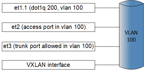
The following sections describe configuring Layer 2 subinterfaces.
Complete the following steps to configure a Layer 2 (L2) subinterface on an Arista switch:
Configure MAC addresses as either static or dynamic as assigned behind Layer 2 (L2) subinterfaces.
Example
switch(config)# mac address-table static 0000.000a.000a vlan 200 interface et1.1switch# show mac address-table interface et1.1-2
Mac Address Table
--------------------------------------------------------
Vlan Mac Address Type Ports Moves Last Move
---- ----------- ---- ----- ----- ---------
200 0000.000a.000a STATIC Et1.1
200 0000.000b.000b DYNAMIC Et1.2 1 0:00:06 ago
Total Mac Addresses for this criterion: 2MAC address learning can be enabled or disabled on an L2 subinterface using the following commands:
switch(config-if-Et1.1)# show interface ethernet1.1 switchport
Name: Et1.1
Switchport: Enabled
Administrative Mode: tunnel
Operational Mode: tunnel
MAC Address Learning: disabled
Dot1q ethertype/TPID: 0x8100 (active)
Dot1q VLAN Tag: Allowed
Access Mode VLAN: 1 (default)
Trunking Native Mode VLAN: 1 (default)
Administrative Native VLAN tagging: disabled
Trunking VLANs Enabled: ALL
Static Trunk Groups:
Dynamic Trunk Groups:
Source interface filtering: enabled
VLAN forwarding mode: allowedVlansOnlyswitch(config-if-Et1.1)# no mac address learning disabledSupported QoS features include the following:
After creating an L2 subinterface, you can configure a shape rate (in Kbps) on the sub-interface. For example, configure the shape rate to 50000000 Kbps.
switch(config-if-Et1.1)# shape rate 50000000| TC6-7 : | VOQ3 |
| TC4-5 : | VOQ2 |
| TC2-3 : | VOQ1 |
| TC0-1 : | VOQ0 |
VOQ3 is in strict-priority mode to the other VOQs.
VOQ2, VOQ1, and VOQ0 are in WRR with a static credit ratio 2:3:6 (higher ratio implies more credits).
The subinterface inherits the trust mode of the parent interface.
Before EOS Release 4.24.2F, EOS supported shaping only on L2 subinterfaces of parent Ethernet interfaces, for example, Et1.1. Beginning with EOS Release 4.24.2F, EOS supports shaping on L2 subinterface over a port-channel parent interface for example, Po1.1).
switch(config-if-Et1.1)# bandwidth guaranteed 10000000
switch(config-if-Et1.1)# bandwidth guaranteed percent 10For policing to work on the L2 subinterface, you must switch to the QoS profile.
Example
switch(config)# hardware tcam
switch(config-hw-tcam)# system profile qos
Sample Policy-map Configuration:
switch(config)# ip access-list a1
switch(config-acl-a1)# statistics per-entry
switch(config-acl-a1)# 10 permit ip any any
switch(config)# class-map type qos match-any c1
switch(config-cmap-qos-c1)# match ip access-group a1
switch(config)# class-map type qos match-any c2
switch(config-cmap-qos-c2)# match vlan 100 0xfff
switch(config)# ipv6 access-list a1
switch(config-ipv6-acl-a1)# statistics per-entry
switch(config-ipv6-acl-a1)# 10 permit ipv6 any any
switch(config)# class-map type qos match-any c3
switch(config-cmap-qos-c3)# match ipv6 access-group a1
switch(config)# policy-map type quality-of-service p1
switch(config-pmap-quality-of-service-p1)# class c1
switch(config-pmap-quality-of-service-p1-c1)# police cir 10 Mbps bc 100000 bytes
exit
exitswitch(config-if-Et1.1)# service-policy type qos input p1To enable the hardware features for counting packets on L2 subinterfaces ingress and/or egress, use the hardware counter feature command, similar to the following example. In the example, enable subinterface layer2 for ingress, and then enable for egress.
switch(config)# hardware counter feature subinterface in layer2
switch(config)# hardware counter feature subinterface out layer2switch# show interfaces et1.1 counters
Port InOctets InPkts
Et1.1 0 0
Port OutOctets OutPkts
Et1.1 0 0switch# clear countersswitch# clear counters et1.1Use the show interfaces status command to display the subinterface status.
switch# show interfaces status sub-interfaces
Port Name Status Vlan Duplex Speed Type Flags Encapsulation
Et1.1 connected 200 full 10G dot1q-encapsulation 100
Et1.2 connected 200 full 10G dot1q-encapsulation 101Use the show vlan command to display the VLAN membership. In the following example, vlan 200 is configured to be displayed.
switch# show vlan 200
VLAN Name Status Ports
----- ------------------- --------- -------------------
200 office active Et1.1, Et1.2, Et5Use the show qos interface command to display the QoS configuration on an L2 subinterface. In the following example, QoS subinterface Ethernet 1.1 is configured to be displayed.
switch# show qos interface Ethernet 1.1
Ethernet1.1:
Trust Mode: DSCP
Default COS: 0
Default DSCP: 0
Port shaping rate: 50625 / 50000 kbpsUse the show interface counters with the queue keyword to display the L2 subinterface counters. For example subinterface Ethernet 1.1 is configured to display the L2 subinterface counters.
switch# show interface Ethernet 1.1 counters queue
Aggregate VoQ Counters
Egress Traffic Pkts Octets DropPkts DropOctets
Port Class
------------------------------------------------------------
Et1.1 TC0-1 0 0 0 0
Et1.1 TC2-3 0 0 0 0
Et1.1 TC4-5 0 0 0 0
Et1.1 TC6-7 460266 276159600 109316 65589600Use the show mac address-table command to display the MAC address on L2 subinterfaces. For example, subinterfaces Et1.1 and Et1.2 are configured to be displayed.
switch# show mac address-table interface et1.1-2
Mac Address Table
------------------------------------------------------------------
Vlan Mac Address Type Ports Moves Last Move
---- ----------- ---- ----- ----- ---------
200 0000.000a.000a STATIC Et1.1
200 0000.000b.000b DYNAMIC Et1.2 1 0:00:16 ago
Total Mac Addresses for this criterion: 2EOS supports Layer2 (L2) Protocol Forwarding on Ethernet interfaces in addition to Type-5 PW. Also, EOS allows selective forwarding of certain L2 Protocol packets, such as tagged, untagged, and all, instead of forwarding all LACP frames, both tagged and untagged. The protocol list for L2 Protocol Forwarding also supports PAUSE, LACP, LLDP, MACsec, and STP. Additionally, L2PF supports the Per-VLAN Spanning Tree (PVST) protocol to forward, drop, or trap PVST packets on Type-2 platforms. EOS enables drop support for all supported protocols.
switch(config-l2-protocol)# forwarding profile abc
switch(config-l2-protocol-abc)# isis forward
switch(config-l2-protocol-abc)# macsec tagged forward
switch(config-l2-protocol-abc)# pause untagged forward
switch(config-l2-protocol-abc)# exitswitch(config)# int ethernet1/1
switch(config-if-Et1/1)# l2-protocol forwarding profile abc
switch(config-if-Et1/1)# exit
switch(config)# int ethernet2/1.1
switch(config-if-Et2/1.1)# l2-protocol forwarding profile def
switch(config-if-Et2/1.1)# exitswitch(config)# hardware tcam
switch(config-tcam)# profile l2protocolfwd
switch(config-tcam-profile-12protocolfwd)# feature acl port ip
switch(config-tcam-feature-acl-port-ip)# sequence 45
switch(config-tcam-feature-acl-port-ip)# key size limit 160
switch(config-tcam-feature-acl-port-ip)# key field dscp dst-ip ip-frag ip-protocol l4-dst-port l4-ops l4-src-port src-ip tcp-control ttl
switch(config-tcam-feature-acl-port-ip)# action count drop
switch(config-tcam-feature-acl-port-ip)# packet ipv4 forwarding bridged
switch(config-tcam-feature-acl-port-ip)# packet ipv4 forwarding routed
switch(config-tcam-feature-acl-port-ip)# packet ipv4 forwarding routed multicast
switch(config-tcam-feature-acl-port-ip)# packet ipv4 mpls ipv4 forwarding mpls decap
switch(config-tcam-feature-acl-port-ip)# packet ipv4 mpls ipv6 forwarding mpls decap
switch(config-tcam-feature-acl-port-ip)# packet ipv4 non-VXLAN forwarding routed decap
switch(config-tcam-feature-acl-port-ip)# packet ipv4 VXLAN eth ipv4 forwarding routed decap
switch(config-tcam-feature-acl-port-ip)# packet ipv4 VXLAN forwarding bridged decap
switch(config-tcam-feature-acl-port-ip)# feature acl port ipv6
switch(config-tcam-feature-acl-port-ipv6)# sequence 25
switch(config-tcam-feature-acl-port-ipv6)# key field dst-ipv6 ipv6-next-header ipv6-traffic-class l4-dst-port l4-ops-3b l4-src-port src-ipv6-high src-ipv6-low tcp-control
switch(config-tcam-feature-acl-port-ipv6)# action count drop
switch(config-tcam-feature-acl-port-ipv6)# packet ipv6 forwarding bridged
switch(config-tcam-feature-acl-port-ipv6)# packet ipv6 forwarding routed
switch(config-tcam-feature-acl-port-ipv6)# packet ipv6 forwarding routed multicast
switch(config-tcam-feature-acl-port-ipv6)# packet ipv6 ipv6 forwarding routed decap
switch(config-tcam-feature-acl-port-ipv6)# feature acl port mac
switch(config-tcam-feature-acl-port-mac)# sequence 55
switch(config-tcam-feature-acl-port-mac)# key size limit 160
switch(config-tcam-feature-acl-port-mac)# key field dst-mac ether-type src-mac
switch(config-tcam-feature-acl-port-mac)# action count drop
switch(config-tcam-feature-acl-port-mac)# packet ipv4 forwarding bridged
switch(config-tcam-feature-acl-port-mac)# packet ipv4 forwarding routed
switch(config-tcam-feature-acl-port-mac)# packet ipv4 forwarding routed multicast
switch(config-tcam-feature-acl-port-mac)# packet ipv4 mpls ipv4 forwarding mpls decap
switch(config-tcam-feature-acl-port-mac)# packet ipv4 mpls ipv6 forwarding mpls decap
switch(config-tcam-feature-acl-port-mac)# packet ipv4 non-VXLAN forwarding routed decap
switch(config-tcam-feature-acl-port-mac)# packet ipv4 VXLAN forwarding bridged decap
switch(config-tcam-feature-acl-port-mac)# packet ipv6 forwarding bridged
switch(config-tcam-feature-acl-port-mac)# packet ipv6 forwarding routed
switch(config-tcam-feature-acl-port-mac)# packet ipv6 forwarding routed decap
switch(config-tcam-feature-acl-port-mac)# packet ipv6 forwarding routed multicast
switch(config-tcam-feature-acl-port-mac)# packet ipv6 ipv6 forwarding routed decap
switch(config-tcam-feature-acl-port-mac)# packet mpls forwarding bridged decap
switch(config-tcam-feature-acl-port-mac)# packet mpls ipv4 forwarding mpls
switch(config-tcam-feature-acl-port-mac)# packet mpls ipv6 forwarding mpls
switch(config-tcam-feature-acl-port-mac)# packet mpls non-ip forwarding mpls
switch(config-tcam-feature-acl-port-mac)# packet non-ip forwarding bridged
switch(config-tcam-feature-acl-port-mac)# feature acl subintf ip
switch(config-tcam-feature-acl-subintf-ip)# sequence 40
switch(config-tcam-feature-acl-subintf-ip)# key size limit 160
switch(config-tcam-feature-acl-subintf-ip)# key field dscp dst-ip ip-frag ip-protocol l4-dst-port l4-ops-18b l4-src-port src-ip tcp-control ttl
switch(config-tcam-feature-acl-subintf-ip)# action count drop
switch(config-tcam-feature-acl-subintf-ip)# packet ipv4 forwarding routed
switch(config-tcam-feature-acl-subintf-ip)# feature acl subintf ipv6
switch(config-tcam-feature-acl-subintf-ipv6)# sequence 15
switch(config-tcam-feature-acl-subintf-ipv6)# key field dst-ipv6 ipv6-next-header l4-dst-port l4-src-port src-ipv6-high src-ipv6-low tcp-control
switch(config-tcam-feature-acl-subintf-ipv6)# action count drop
switch(config-tcam-feature-acl-subintf-ipv6)# packet ipv6 forwarding routed
switch(config-tcam-feature-acl-subintf-ipv6)# feature acl vlan ip
switch(config-tcam-feature-acl-vlan-ip)# sequence 35
switch(config-tcam-feature-acl-vlan-ip)# key size limit 160
switch(config-tcam-feature-acl-vlan-ip)# key field dscp dst-ip ip-frag ip-protocol l4-dst-port l4-ops-18b l4-src-port src-ip tcp-control ttl
switch(config-tcam-feature-acl-vlan-ip)# action count drop
switch(config-tcam-feature-acl-vlan-ip)# packet ipv4 forwarding routed
switch(config-tcam-feature-acl-vlan-ip)# packet ipv4 mpls ipv4 forwarding mpls decap
switch(config-tcam-feature-acl-vlan-ip)# packet ipv4 mpls ipv6 forwarding mpls decap
switch(config-tcam-feature-acl-vlan-ip)# packet ipv4 non-VXLAN forwarding routed decap
switch(config-tcam-feature-acl-vlan-ip)# packet ipv4 VXLAN eth ipv4 forwarding routed decap
switch(config-tcam-feature-acl-vlan-ip)# feature acl vlan ipv6
switch(config-tcam-feature-acl-vlan-ipv6)# sequence 10
switch(config-tcam-feature-acl-vlan-ipv6)# key field dst-ipv6 ipv6-next-header l4-dst-port l4-src-port src-ipv6-high src-ipv6-low tcp-control
switch(config-tcam-feature-acl-vlan-ipv6)# action count drop
switch(config-tcam-feature-acl-vlan-ipv6)# packet ipv6 forwarding routed
switch(config-tcam-feature-acl-vlan-ipv6)# packet ipv6 ipv6 forwarding routed decap
switch(config-tcam-feature-acl-vlan-ipv6)# feature acl vlan ipv6 egress
switch(config-tcam-feature-acl-vlan-ipv6-egress)# sequence 20
switch(config-tcam-feature-acl-vlan-ipv6-egress)# key field dst-ipv6 ipv6-next-header ipv6-traffic-class l4-dst-port l4-src-port src-ipv6-high src-ipv6-low tcp-control
switch(config-tcam-feature-acl-vlan-ipv6-egress)# action count drop
switch(config-tcam-feature-acl-vlan-ipv6-egress)# packet ipv6 forwarding routed
switch(config-tcam-feature-acl-vlan-ipv6-egress)# feature counter lfib
switch(config-tcam-feature-counter-lfib)# sequence 85
switch(config-tcam-feature-counter-lfib)# feature l2-protocol forwarding
switch(config-tcam-feature-l2-protocol-fowarding)# sequence 95
switch(config-tcam-feature-l2-protocol-fowarding)# key size limit 160
switch(config-tcam-feature-l2-protocol-fowarding)# key field dst-mac vlan-tag-format
switch(config-tcam-feature-l2-protocol-fowarding)# action mirror redirect-to-cpu set-tc
switch(config-tcam-feature-l2-protocol-fowarding)# packet non-ip forwarding bridge
switch(config-tcam-feature-l2-protocol-fowarding)# packet non-ip forwarding bridged sub-interface
switch(config-tcam-feature-l2-protocol-fowarding)# feature mirror ip
switch(config-tcam-feature-mirror-ip)# sequence 80
switch(config-tcam-feature-mirror-ip)# key size limit 160
switch(config-tcam-feature-mirror-ip)# key field dscp dst-ip ip-frag ip-protocol l4-dst-port l4-ops l4-src-port src-ip tcp-control
switch(config-tcam-feature-mirror-ip)# action count mirror set-policer
switch(config-tcam-feature-mirror-ip)# packet ipv4 forwarding bridged
switch(config-tcam-feature-mirror-ip)# packet ipv4 forwarding routed
switch(config-tcam-feature-mirror-ip)# packet ipv4 forwarding routed multicast
switch(config-tcam-feature-mirror-ip)# packet ipv4 non-VXLAN forwarding routed decap
switch(config-tcam-feature-mirror-ip)# feature mpls
switch(config-tcam-feature-mpls)# sequence 5
switch(config-tcam-feature-mpls)# key size limit 160
switch(config-tcam-feature-mpls)# action drop redirect set-ecn
switch(config-tcam-feature-mpls)# packet ipv4 mpls ipv4 forwarding mpls decap
switch(config-tcam-feature-mpls)# packet ipv4 mpls ipv6 forwarding mpls decap
switch(config-tcam-feature-mpls)# packet mpls ipv4 forwarding mpls
switch(config-tcam-feature-mpls)# packet mpls ipv6 forwarding mpls
switch(config-tcam-feature-mpls)# packet mpls non-ip forwarding mpls
switch(config-tcam-feature-mpls)# feature mpls pop ingress
switch(config-tcam-feature-mpls-pop-ingress)# sequence 90
switch(config-tcam-feature-mpls-pop-ingress)# feature pbr ip
switch(config-tcam-feature-pbr-ip)# sequence 60
switch(config-tcam-feature-pbr-ip)# key size limit 160
switch(config-tcam-feature-pbr-ip)# key field dscp dst-ip ip-frag ip-protocol l4-dst-port l4-ops-18b l4-src-port src-ip tcp-control
switch(config-tcam-feature-pbr-ip)# action count redirect
switch(config-tcam-feature-pbr-ip)# packet ipv4 forwarding routed
switch(config-tcam-feature-pbr-ip)# packet ipv4 mpls ipv4 forwarding mpls decap
switch(config-tcam-feature-pbr-ip)# packet ipv4 mpls ipv6 forwarding mpls decap
switch(config-tcam-feature-pbr-ip)# packet ipv4 non-VXLAN forwarding routed decap
switch(config-tcam-feature-pbr-ip)# packet ipv4 VXLAN forwarding bridged decap
switch(config-tcam-feature-pbr-ip)# feature pbr ipv6
switch(config-tcam-feature-pbr-ipv6)# sequence 30
switch(config-tcam-feature-pbr-ipv6)# key field dst-ipv6 ipv6-next-header l4-dst-port l4-src-port src-ipv6-high src-ipv6-low tcp-control
switch(config-tcam-feature-pbr-ipv6)# action count redirect
switch(config-tcam-feature-pbr-ipv6)# packet ipv6 forwarding routed
switch(config-tcam-feature-pbr-ipv6)# feature pbr mpls
switch(config-tcam-feature-pbr-mpls)# sequence 65
switch(config-tcam-feature-pbr-mpls)# key size limit 160
switch(config-tcam-feature-pbr-mpls)# key field mpls-inner-ip-tos
switch(config-tcam-feature-pbr-mpls)# action count drop redirect
switch(config-tcam-feature-pbr-mpls)# packet mpls ipv4 forwarding mpls
switch(config-tcam-feature-pbr-mpls)# packet mpls ipv6 forwarding mpls
switch(config-tcam-feature-pbr-mpls)# packet mpls non-ip forwarding mpls
switch(config-tcam-feature-pbr-mpls)# feature qos ip
switch(config-tcam-feature-qos-ip)# sequence 75
switch(config-tcam-feature-qos-ip)# key size limit 160
switch(config-tcam-feature-qos-ip)# key field dscp dst-ip ip-frag ip-protocol l4-dst-port l4-ops l4-src-port src-ip tcp-control
switch(config-tcam-feature-qos-ip)# action set-dscp set-policer set-tc
switch(config-tcam-feature-qos-ip)# packet ipv4 forwarding routed
switch(config-tcam-feature-qos-ip)# packet ipv4 forwarding routed multicast
switch(config-tcam-feature-qos-ip)# packet ipv4 mpls ipv4 forwarding mpls decap
switch(config-tcam-feature-qos-ip)# packet ipv4 mpls ipv6 forwarding mpls decap
switch(config-tcam-feature-qos-ip)# packet ipv4 non-VXLAN forwarding routed decap
switch(config-tcam-feature-qos-ip)# feature qos ipv6
switch(config-tcam-feature-qos-ipv6)# sequence 70
switch(config-tcam-feature-qos-ipv6)# key field dst-ipv6 ipv6-next-header ipv6-traffic-class l4-dst-port l4-src-port src-ipv6-high src-ipv6-low
switch(config-tcam-feature-qos-ipv6)# action set-dscp set-policer set-tc
switch(config-tcam-feature-qos-ipv6)# packet ipv6 forwarding routed
switch(config-tcam-feature-qos-ipv6)# feature tunnel VXLAN
switch(config-tcam-feature-tunnel-VXLAN)# sequence 50
switch(config-tcam-feature-tunnel-VXLAN)# key size limit 160
switch(config-tcam-feature-tunnel-VXLAN)# packet ipv4 VXLAN eth ipv4 forwarding routed decap
switch(config-tcam-feature-tunnel-VXLAN)# packet ipv4 VXLAN forwarding bridged decapswitch(config-tcam)# feature l2-protocol forwarding
switch(config-tcam-l2-protocol forwarding)# sequence 95
switch(config-tcam-l2-protocol forwarding)# key size limit 160
switch(config-tcam-l2-protocol forwarding)# key field dst-mac vlan-tag-format
switch(config-tcam-l2-protocol forwarding)# action mirror redirect-to-cpu set-tc snoop
switch(config-tcam-l2-protocol forwarding)# packet non-ip forwarding bridged
switch(config-tcam-l2-protocol forwarding)# packet non-ip forwarding bridged sub-interfaceswitch(config)# hardware tcam
switch(config-tcam)# profile l2protocolfwd-bfd-rfc-7130
switch(config-tcam-profile l2protocolfwd-bfd-rfc-7130)# feature acl port ip egress mpls-tunnelled-match
switch(config-tcam-feature-acl-port-ip-egress-mpls-tunnelled-match)# sequence 95
switch(config-tcam-feature-acl-port-ip-egress-mpls-tunnelled-match)# feature acl port ipv6 egress
switch(config-tcam-feature-acl-port-ipv6-egress)# sequence 105
switch(config-tcam-feature-acl-port-ipv6-egress)# key field dst-ipv6 ipv6-next-header ipv6-traffic-class l4-dst-port l4-src-port src-ipv6-high src-ipv6-low tcp-control
switch(config-tcam-feature-acl-port-ipv6-egress)# action count drop mirror
switch(config-tcam-feature-acl-port-ipv6-egress)# packet ipv6 forwarding bridged
switch(config-tcam-feature-acl-port-ipv6-egress)# packet ipv6 forwarding routed
switch(config-tcam-feature-acl-port-ipv6-egress)# feature acl port mac
switch(config-tcam-feature-acl-port-mac)# sequence 55
switch(config-tcam-feature-acl-port-mac)# key size limit 160
switch(config-tcam-feature-acl-port-mac)# key field dst-mac ether-type src-mac
switch(config-tcam-feature-acl-port-mac)# action count drop mirror
switch(config-tcam-feature-acl-port-mac)# packet ipv4 forwarding bridged
switch(config-tcam-feature-acl-port-mac)# packet ipv4 forwarding routed
switch(config-tcam-feature-acl-port-mac)# packet ipv4 forwarding routed multicast
switch(config-tcam-feature-acl-port-mac)# packet ipv4 mpls ipv4 forwarding mpls decap
switch(config-tcam-feature-acl-port-mac)# packet ipv4 mpls ipv6 forwarding mpls decap
switch(config-tcam-feature-acl-port-mac)# packet ipv4 non-VXLAN forwarding routed decap
switch(config-tcam-feature-acl-port-mac)# packet ipv4 VXLAN forwarding bridged decap
switch(config-tcam-feature-acl-port-mac)# packet ipv6 forwarding bridged
switch(config-tcam-feature-acl-port-mac)# packet ipv6 forwarding routed
switch(config-tcam-feature-acl-port-mac)# packet ipv6 forwarding routed decap
switch(config-tcam-feature-acl-port-mac)# packet ipv6 forwarding routed multicast
switch(config-tcam-feature-acl-port-mac)# packet ipv6 ipv6 forwarding routed decap
switch(config-tcam-feature-acl-port-mac)# packet mpls forwarding bridged decap
switch(config-tcam-feature-acl-port-mac)# packet mpls ipv4 forwarding mpls
switch(config-tcam-feature-acl-port-mac)# packet mpls ipv6 forwarding mpls
switch(config-tcam-feature-acl-port-mac)# packet mpls non-ip forwarding mpls
switch(config-tcam-feature-acl-port-mac)# packet non-ip forwarding bridged
switch(config-tcam-feature-acl-port-mac)# feature acl subintf ip
switch(config-tcam-feature-acl-subintf-ip)# sequence 40
switch(config-tcam-feature-acl-subintf-ip)# key size limit 160
switch(config-tcam-feature-acl-subintf-ip)# key field dscp dst-ip ip-frag ip-protocol l4-dst-port l4-ops-18b l4-src-port src-ip tcp-control ttl
switch(config-tcam-feature-acl-subintf-ip)# action count drop
switch(config-tcam-feature-acl-subintf-ip)# packet ipv4 forwarding routed
switch(config-tcam-feature-acl-subintf-ip)# feature acl subintf ipv6
switch(config-tcam-feature-acl-subintf-ipv6)# sequence 15
switch(config-tcam-feature-acl-subintf-ipv6)# key field dst-ipv6 ipv6-next-header l4-dst-port l4-src-port src-ipv6-high src-ipv6-low tcp-control
switch(config-tcam-feature-acl-subintf-ipv6)# action count drop
switch(config-tcam-feature-acl-subintf-ipv6)# packet ipv6 forwarding routed
switch(config-tcam-feature-acl-subintf-ipv6)# feature acl vlan ip
switch(config-tcam-feature-acl-vlan-ip)# sequence 35
switch(config-tcam-feature-acl-vlan-ip)# key size limit 160
switch(config-tcam-feature-acl-vlan-ip)# key field dscp dst-ip ip-frag ip-protocol l4-dst-port l4-ops-18b l4-src-port src-ip tcp-control ttl
switch(config-tcam-feature-acl-vlan-ip)# action count drop
switch(config-tcam-feature-acl-vlan-ip)# packet ipv4 forwarding routed
switch(config-tcam-feature-acl-vlan-ip)# packet ipv4 mpls ipv4 forwarding mpls decap
switch(config-tcam-feature-acl-vlan-ip)# packet ipv4 mpls ipv6 forwarding mpls decap
switch(config-tcam-feature-acl-vlan-ip)# packet ipv4 non-VXLAN forwarding routed decap
switch(config-tcam-feature-acl-vlan-ip)# packet ipv4 VXLAN eth ipv4 forwarding routed decap
switch(config-tcam-feature-acl-vlan-ip)# feature acl vlan ipv6
switch(config-tcam-feature-acl-vlan-ipv6)# sequence 10
switch(config-tcam-feature-acl-vlan-ipv6)# key field dst-ipv6 ipv6-next-header l4-dst-port l4-src-port src-ipv6-high src-ipv6-low tcp-control
switch(config-tcam-feature-acl-vlan-ipv6)# action count drop
switch(config-tcam-feature-acl-vlan-ipv6)# packet ipv6 forwarding routed
switch(config-tcam-feature-acl-vlan-ipv6)# packet ipv6 ipv6 forwarding routed decap
switch(config-tcam-feature-acl-vlan-ipv6)# feature acl vlan ipv6 egress
switch(config-tcam-feature-acl-vlan-ipv6-egress)# sequence 20
switch(config-tcam-feature-acl-vlan-ipv6-egress)# key field dst-ipv6 ipv6-next-header ipv6-traffic-class l4-dst-port l4-src-port src-ipv6-high src-ipv6-low tcp-control
switch(config-tcam-feature-acl-vlan-ipv6-egress)# action count drop mirror
switch(config-tcam-feature-acl-vlan-ipv6-egress)# packet ipv6 forwarding bridged
switch(config-tcam-feature-acl-vlan-ipv6-egress)# packet ipv6 forwarding routed
switch(config-tcam-feature-acl-vlan-ipv6-egress)# feature counter lfib
switch(config-tcam-feature-counter-lfib)# sequence 85
switch(config-tcam-feature-counter-lfib)# feature forwarding-destination mpls
switch(config-tcam-feature-forwarding-destination-mpls)# sequence 100
switch(config-tcam-feature-forwarding-destination-mpls)# feature l2-protocol forwarding
switch(config-tcam-feature-forwarding-l2-protocol-forwarding)# sequence 95
switch(config-tcam-feature-forwarding-l2-protocol-forwarding)# key size limit 160
switch(config-tcam-feature-forwarding-l2-protocol-forwarding)# key field dst-mac vlan-tag-format
switch(config-tcam-feature-forwarding-l2-protocol-forwarding)# action mirror redirect-to-cpu set-tc
switch(config-tcam-feature-forwarding-l2-protocol-forwarding)# packet ipv4 forwarding bridged
switch(config-tcam-feature-forwarding-l2-protocol-forwarding)# packet ipv6 forwarding bridged
switch(config-tcam-feature-forwarding-l2-protocol-forwarding)# packet non-ip forwarding bridged
switch(config-tcam-feature-forwarding-l2-protocol-forwarding)# feature mirror ip
switch(config-tcam-feature-mirror-ip)# sequence 80
switch(config-tcam-feature-mirror-ip)# key size limit 160
switch(config-tcam-feature-mirror-ip)# key field dscp dst-ip ip-frag ip-protocol l4-dst-port l4-ops l4-src-port src-ip tcp-control
switch(config-tcam-feature-mirror-ip)# action count mirror set-policer
switch(config-tcam-feature-mirror-ip)# packet ipv4 forwarding bridged
switch(config-tcam-feature-mirror-ip)# packet ipv4 forwarding routed
switch(config-tcam-feature-mirror-ip)# packet ipv4 forwarding routed multicast
switch(config-tcam-feature-mirror-ip)# packet ipv4 non-VXLAN forwarding routed decap
switch(config-tcam-feature-mirror-ip)# feature mpls
switch(config-tcam-feature-mpls)# sequence 5
switch(config-tcam-feature-mpls)# key size limit 160
switch(config-tcam-feature-mpls)# action drop redirect set-ecn
switch(config-tcam-feature-mpls)# packet ipv4 mpls ipv4 forwarding mpls decap
switch(config-tcam-feature-mpls)# packet ipv4 mpls ipv6 forwarding mpls decap
switch(config-tcam-feature-mpls)# packet mpls ipv4 forwarding mpls
switch(config-tcam-feature-mpls)# packet mpls ipv6 forwarding mpls
switch(config-tcam-feature-mpls)# packet mpls non-ip forwarding mpls
switch(config-tcam-feature-mpls)# feature mpls pop ingress
switch(config-tcam-feature-mpls-pop-ingress)# sequence 90
switch(config-tcam-feature-mpls-pop-ingress)# feature pbr ip
switch(config-tcam-feature-pbr-ip)# sequence 60
switch(config-tcam-feature-pbr-ip)# key size limit 160
switch(config-tcam-feature-pbr-ip)# key field dscp dst-ip ip-frag ip-protocol l4-dst-port l4-ops-18b l4-src-port src-ip tcp-control
switch(config-tcam-feature-pbr-ip)# action count redirect
switch(config-tcam-feature-pbr-ip)# packet ipv4 forwarding routed
switch(config-tcam-feature-pbr-ip)# packet ipv4 mpls ipv4 forwarding mpls decap
switch(config-tcam-feature-pbr-ip)# packet ipv4 mpls ipv6 forwarding mpls decap
switch(config-tcam-feature-pbr-ip)# packet ipv4 non-VXLAN forwarding routed decap
switch(config-tcam-feature-pbr-ip)# packet ipv4 VXLAN forwarding bridged decap
switch(config-tcam-feature-pbr-ip)# feature pbr ipv6
switch(config-tcam-feature-pbr-ipv6)# sequence 30
switch(config-tcam-feature-pbr-ipv6)# key field dst-ipv6 ipv6-next-header l4-dst-port l4-src-port src-ipv6-high src-ipv6-low tcp-control
switch(config-tcam-feature-pbr-ipv6)# action count redirect
switch(config-tcam-feature-pbr-ipv6)# packet ipv6 forwarding routed
switch(config-tcam-feature-pbr-ipv6)# feature pbr mpls
switch(config-tcam-feature-pbr-mpls)# sequence 65
switch(config-tcam-feature-pbr-mpls)# key size limit 160
switch(config-tcam-feature-pbr-mpls)# key field mpls-inner-ip-tos
switch(config-tcam-feature-pbr-mpls)# action count drop redirect
switch(config-tcam-feature-pbr-mpls)# packet mpls ipv4 forwarding mpls
switch(config-tcam-feature-pbr-mpls)# packet mpls ipv6 forwarding mpls
switch(config-tcam-feature-pbr-mpls)# packet mpls non-ip forwarding mpls
switch(config-tcam-feature-pbr-mpls)# feature qos ip
switch(config-tcam-feature-qos-ip)# sequence 75
switch(config-tcam-feature-qos-ip)# key size limit 160
switch(config-tcam-feature-qos-ip)# key field dscp dst-ip ip-frag ip-protocol l4-dst-port l4-ops l4-src-port src-ip tcp-control
switch(config-tcam-feature-qos-ip)# action set-dscp set-policer set-tc
switch(config-tcam-feature-qos-ip)# packet ipv4 forwarding routed
switch(config-tcam-feature-qos-ip)# packet ipv4 forwarding routed multicast
switch(config-tcam-feature-qos-ip)# packet ipv4 mpls ipv4 forwarding mpls decap
switch(config-tcam-feature-qos-ip)# packet ipv4 mpls ipv6 forwarding mpls decap
switch(config-tcam-feature-qos-ip)# packet ipv4 non-VXLAN forwarding routed decap
switch(config-tcam-feature-qos-ip)# feature qos ipv6
switch(config-tcam-feature-qos-ipv6)# sequence 70
switch(config-tcam-feature-qos-ipv6)# key field dst-ipv6 ipv6-next-header ipv6-traffic-class l4-dst-port l4-src-port src-ipv6-high src-ipv6-low
switch(config-tcam-feature-qos-ipv6)# action set-dscp set-policer set-tc
switch(config-tcam-feature-qos-ipv6)# packet ipv6 forwarding routed
switch(config-tcam-feature-qos-ipv6)# feature tunnel VXLAN
switch(config-tcam-feature-tunnel-VXLAN)# sequence 50
switch(config-tcam-feature-tunnel-VXLAN)# key size limit 160
switch(config-tcam-feature-tunnel-VXLAN)# packet ipv4 VXLAN eth ipv4 forwarding routed decap
switch(config-tcam-feature-tunnel-VXLAN)# packet ipv4 VXLAN forwarding bridged decapswitch(config)# hardware tcam
switch(config-tcam)# system profile l2protocolfwdThe following table describes how TCAM is consumed when the same L2 Protocol Forwarding profile is applied:
| Level of application | Type-1 platforms | Type-2 platforms |
|---|---|---|
| Front panel ports | Separate TCAM entries for each port | Same set of TCAM entries for ports on the same fap and core |
| Subinterfaces | Same set of TCAM entries for subinterfaces on the same fap | Same set of TCAM entries for subinterfaces on the same fap and core |
feature pbr subintf ipfeature pbr subintf ipv6feature pbr subintf mplsshow l2-protocol forwarding interface command displays the L2
protocol forwarding profile configuration corresponding to the interface or
subinterface.switch(config)# show l2-protocol forwarding interface
Interface Profile
------------- -------
Ethernet1/1 abc
Ethernet2/1.1 def
switch> show l2-protocol forwarding interface Ethernet1/1
Interface Profile
----------- --------
Ethernet1/1 abcswitch(config)# show l2-protocol forwarding interface detail
Tagging Types: T: tagged U: untagged
Actions: F: forward
BFD RFC-7130 E-LMI ISIS LACP LLDP MACSEC PAUSE STP
Interface Profile T U T U T U T U T U T U T U T U
------------- ------- ----- ------ -- -- - -- - -- - -- -- --- -- -- - -
Ethernet1/1 abc - - - - F F - - - - F - - F - -
Ethernet2/2.1 def - - - - - - - - - - - - - - - -
switch> show l2-protocol forwarding interface Ethernet1/1 detail
Tagging Types: T: tagged U: untagged
Actions: F: forward
BFD RFC-7130 E-LMI ISIS LACP LLDP MACSEC PAUSE STP
Interface Profile T U T U T U T U T U T U T U T U
------------- ------- ----- ------ -- -- - -- - -- - -- -- --- -- -- - -
Ethernet1/1 abc - - - - F F - - - - F - - F - -
switch> show l2-protocol forwarding interface Ethernet2/2.1 detail
Tagging Types: T: tagged U: untagged
Actions: F: forward
BFD RFC-7130 E-LMI ISIS LACP LLDP MACSEC PAUSE STP
Interface Profile T U T U T U T U T U T U T U T U
------------- ------- ----- ------ -- -- - -- - -- - -- -- --- -- -- - -
Ethernet2/2.1 def - - - - - - - - - - - - - - - -EOS provides IP Address Locking capabilities when configured on an Ethernet Layer 2 port.
After enabling IP Address Locking on a Layer 2 (L2) port, the port only permits IP and ARP packets with authorized IP source addresses. Configure IP Address Locking in one of two modes:
IP Address Locking prevents a host on a different interface from claiming ownership of an IP address through ARP spoofing. IPv6 Locking extends this behavior to IPv6 packets, including ICMPv6 Neighbor Discovery Router Advertisement and Redirect and DHCP server-to-client packets.
On an IPv6 Locked Port, the ARP protocol performs the following actions on the network:
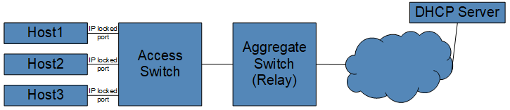
IP Address Locking determines port authorization for IP addresses by untilizing DHCP LeaseQuery and MAC address. Ensure that DHCP servers used in the network allow LeaseQuery messages.
Alternatively, IP locking can be configured to monitor incoming DHCPACK packets on designated ports to verify IP address authorization. This specific configuration method operates independently and eliminates the need for DHCP LeaseQuery.
This section describes IP Locking configuration tasks. Topics in this section include:
Before enabling IPv4 Address Locking, you must configure a DHCP Server and a Local Layer 3 interface.
Add the DHCP servers used by hosts to acquire leases. IPv4 Address Locking communicates with the DHCP servers to learn the authorized IP addresses on the switch.
Example
switch(config-address-locking)# dhcp server ipv4 10.1.1.1
switch(config-address-locking)# dhcp server ipv4 10.30.1.3Add a local L3 interface to communicate with the DHCP server. This could be the management interface, a routed interface, or a Switch Virtual Interface (SVI). This interface requires an assigned valid IP address, routable to the configured DHCP server, and can reside in a non-default VRF. The switch packets sent to the DHCP Server use the interface IP address as the source IP address.
Examples
switch# configure
switch(config)# interface Vlan2160
switch(config-if-Vl2160)# ip address 10.10.1.2/16switch# configure
switch(config)# address locking
switch(config-address-locking)# local-interface Vlan2160Configure IP Address Locking for either IPv4 or IPv6 addresses, and both types of IP addresses can be enabled for IP Address Locking. IPv6 Address Locking requires a different approach outlined in this section.
Configure IPv4 Address Locking commands in the configuration mode.
Example
switch# configure
switch(config)# address locking
switch(config-address-locking)# locked-address ipv4To enable IPv6 locking, disable the enforcement of IPv6 Address Locking.
Example
switch# configure
switch(config)# address locking
switch(config-address-locking)# locked-address ipv6 enforcement disabled
switch(config-address-locking)# locked-address ipv6Disable IP Address Locking using the disabled command in address-locking mode. This turns off the feature and allows a host to use any IP address, authorized or unauthorized, on any port.
switch# configure
switch(config)# address locking
switch(config-address-locking)# disabledTo enable IPv4 Address Locking on ports connected to clients, IP Address Locking must be enabled in the Interface Configuration Mode. Running this command only enables IPv4 Locking and overrides the previous configuration for the interface.
Example
switch(config)# interface Ethernet27/1
switch(config-if-Et27/1)# address locking
switch(config-if-Et27/1-address-locking)# address-family ipv4Use the following commands to enable IPv6 Address Locking on ports connected to clients, use the address-family ipv6 parameter.
Example
switch(config)# interface Ethernet53/4
switch(config-if-Et53/4)# address locking
switch(config-if-Et53/4-address-locking)# address-family ipv6To activate IP Address Locking on all VLAN port members, use the VLAN address locking configuration submode.
Examples
switch(config)# vlan 20
switch(config-vlan-20)# address locking
switch(config-vlan-20-addr-lock)# address-family ipv4To exclude a VLAN port member, disable IP Address Locking on that port using the interface configuration submode.
switch(config)# interface Ethernet2/25
switch(config-if-Et2/25)# address locking
switch(config-if-Et2/25)# address-family ipv4 disabledTo configure IPv6 Address Locking on all ports, use the same commands, but designate the address-family as ipv6.
switch(config)# interface Ethernet 27/1
switch(config-if-Et27/1)# address locking
switch(config-if-Et27/1-address-locking)# address-family ipv6switch(config)# vlan 20
switch(config-vlan-20)# address locking
switch(config-vlan-20-addr-lock)# address-family ipv6switch(config)# interface Ethernet 27/1
switch(config-if-Et27/1)# address locking
switch(config-if-Et27/1-address-locking)# address-family ipv4
switch(config-if-Et27/1-address-locking)# address-family ipv6Use the deny ip_address on IPv4 Address Locking ports to block all IPv4 and ARP packets with a specific source IPv4 address. The port denies the packet and affects only IPv4 enforcement modes. This action deauthorizes the addresses on the port and can be configured with multiple IPv4 addresses. You must configure this on an interface already configured with IPv4 Address Locking.
switch(config)# interface Ethernet27/1
switch(config-if-Et27/1)# address locking
switch(config-if-Et27/1-addr-lock)# deny 172.21.16.25The lease mac command within address locking configuration mode installs a lease into hardware for the configured IP address on the interface with the configured associated MAC address. If the MAC address does not appear in the MAC table or the MAC address on an interface without a configured IP Locking feature, the lease does not install until the interface adds the MAC address to an interface configured with IP Locking.
Example
switch# configure
switch(config)# address locking
switch(config-address-locking)# lease 172.21.13.11 mac a0:ce:c8:b1:78:d3The command, lease query retry interval interval timeout minutes configures sending lease queries at specific retry intervals. The no lease query retry command removes the retry interval and timeout configuration.
Example
switch(config)# address locking
switch(config-address-locking)# lease query retry interval 5 timeout 100When IP Address Locking sends out a LeaseQuery request, and does not receive a LeaseActive reply, IP Address Locking sends six (6) additional retries over 64 seconds using an exponential backoff algorithm. A 0-25% delay sending requests which may take up to 80 seconds to send out all seven (7) requests.
Every LeaseQuery request includes a transaction ID. After sending the last request, and for an additional 10 seconds, IP Address Locking accepts any LeaseActive reply matching the transaction ID and then queries for the MAC address of a sent LeaseQuery request.
If a LeaseActive reply contains multiple IP addresses, IP Address Locking begins a query process for the additional IP addresses using the same retry mechanisms. However, if you configure the LeaseQuery retry interval and timeout but do not receive LeaseActive replies, IP Address Locking sends continuous lease query requests at the configured retry interval until reaching the specified timeout period.
The IP addresses remain authorized and installed after the corresponding MAC addresses age out. IP Address Locking, by default, removes authorized leases after the corresponding MAC addresses age out. The locked-address expiration mac disabled command configures IP Address Locking to keep leases installed, after the corresponding MAC addresses age out.
Example
switch# configure
switch(config)# address locking
switch(config-address-locking)# locked-address expiration mac disabledAddress-locking mode can be enabled using the command dhcp server
interface <INTF>. In this mode, the IP Locking agent monitors
the server interface for DHCP ACK packets and tracks release packets on protected
interfaces.
Configuration Priorities and DHCP Lease Management
When both a local interface and a DHCP server interface are specified, the
system prioritizes the local-interface <INTF> setting. In
this scenario, IP Locking disregards the DHCP server interface and utilizes the local
interface for outgoing DHCP LeaseQuery messages.
Furthermore, specifying DHCP server IP addresses within the dhcp
server interface <INTF> configuration is optional. If specific
IP addresses are provided, IP Locking strictly learns leases from those identified
servers. However, if no addresses are defined, the agent will learn leases from all DHCP
server traffic detected on the configured interfaces.
Example
Use the following command to configure the dhcp server interface Ethernet 28/1:
switch#config
switch(config)#address locking
switch(config-address-locking)#dhcp server interface Ethernet28/1The locked-address ipv4 enforcement disabled command disables address filtering for all ports with IPv4 Address Locking enabled. This permits IPv4 packets while still keeping all other drop rules. When configured, IP Address Locking does not drop IP or ARP packets, and does not send out lease queries to configured DHCP servers.
Examples
switch# configure
switch(config)# address locking
switch(config-address-locking)# locked-address ipv4 enforcement disabledswitch(config)# interface Ethernet27/1
switch(config-if-Et27/1)# address locking
switch(config-if-Et27/1-address-locking)# locked-address ipv4 enforcement disabled switch(config)# vlan 20
switch(config-vlan-20)# address locking
switch(config-vlan-20-addr-lock)# locked-address ipv4 enforcement disabledswitch# configure
switch(config)# address locking
switch(config-address-locking)# locked-address ipv6 enforcement disabledswitch(config)# interface Ethernet27/1
switch(config-if-Et27/1)# address locking
switch(config-if-Et27/1-address-locking)# locked-address ipv6 enforcement disabledswitch(config)# vlan 20
switch(config-vlan-20)# address locking
switch(config-vlan-20-addr-lock)# locked-address ipv6 enforcement disabledThe output displays separate counters for the different types of messages communicated between the switch and the DHCP server.
switch# show address locking counters
Lease Active Lease Unknown Lease Unassigned
DHCP Server Query Rcvd Drop Rcvd Drop Rcvd Drop Unknown
----------- ----- ----- ------ ------ ------ -------- ------- -------
80.80.80.80 32860 8002 34 8001 32 13423 134 3234
Interface Query Lease Active Lease Unknown Lease Unassigned
--------- ----- ------------ ------------- ----------------
Ethernet2 1747 1234 189 324The clear address locking counters command resets all the counters associated with IP Locking to zero.
Use the show address locking command to display the status of IPv4 and IPv6 locking.
switch# show address locking
IP Locking is active
Interface IPv4 IPv6
--------------- ------------------- ---------------------------
Ethernet27/1 yes no (not configured)
Ethernet31/1 no (not configured) no (not a layer 2 interface)The show address locking table ipv4 command displays all the DHCP leases that IP Address Locking knows about, current status of installed leases, and the authorized interfaces for these IP addresses.
switch# show address locking table ipv4
IP Address MAC Address Interface Installed Expiration Time
-------------- ---------------- ---------- ------------ ---------------
10.30.4.4 ba76.a467.7ff8 Et27/1 installed in 0:01:57 IP Address Locking Configuration Commands
Use the address locking command to block IPv4 and ARP packets with specific IPv4 addresses on the switch. You must perform this command from an interface configured for IP Address Locking on the switch.
Command Mode
Interface Configuration
Address Locking Configuration
Command Syntax
address locking deny ip_address
Parameter
ip_address - Specify the IPv4 address to block packets.
Example
Use the following command to deny IPv4 and ARP packets from IPv4 address, 172.16.21.131, from Ethernet interface, Ethernet53/4:
switch(config)# interface Ethernet53/4
switch(config-if-Et53/4)# address locking
switch(config-address-locking)# deny 172.16.21.131Use the address locking command to enter address locking mode and then dhcp to configure the DHCP server.
Command Mode
Address Locking Configuration
Command Syntax
address locking dhcp server ipv4 ip_address
Parameters
Example
To configure a DHCP server with an IPv4 address. 172.13.21.3, use the following command:
switch(config)# address locking
switch(config-address-locking)# dhcp server ipv4 172.13.21.3The address-locking disable command disables IP Address Locking on a switch.
Command Mode
Address Locking Configuration
Command Syntax
address-locking disable
Example
switch(config)# address-locking
switch(config-address-locking)# disableUse the address locking command to enter the IPv4 and IPv6 locking mode and then on the switch, use the lease to configure DHCP leases.
The lease mac command within the address locking configuration mode installs a lease onto hardware for the configured IP address on the interface with the associated configured MAC address. If the MAC address does not exist in the MAC table or the MAC address appears on an interface with an IP Locking configuration feature, the lease does not install until you add the MAC address to an interface configured with IP Locking.
Command Mode
Address Locking Configuration
Command Syntax
lease ip_address mac ip_address
Parameters
Example
To configure a lease with the IPv4 address, 1.1.1.1, and the MAC address, a.b.c, use the following command:
switch(config)# address locking
switch(config-address-locking)# lease 1.1.1.1 mac a.b.cUse the address locking command to enter the IPv4 and IPv6 locking mode and then use the lease query retry interval to configure DHCP leases.
The no lease query retry command removes the retry interval and timeout configuration.
Command Mode
Address Locking Configuration
Command Syntax
lease query retry interval interval-time
Parameters
interval interval-time - Configure the query retry interval and timeout. The interval can be from 1 - 4294967295 seconds.
Example
switch(config)# address locking
switch(config-address-locking)# lease query retry interval 5 timeout 100Use the address locking local-interface command to configure a local interface for IPv4 and IPv6 locking IP addresses on the switch.
Command Mode
Address Locking Configuration
Command Syntax
address locking local-interface [Ethernet | Loopback | Management | Port Channel | Tunnel | Vlan]
Parameters
Example
To configure an Ethernet interface, Ethernet53/4, use the following command:
switch(config)# address locking
switch(config-address-locking)# local-interface Ethernet53/4Use the clear address locking lease command to remove lease bindings at different granularities.
Command Mode
Address Locking mode
Command Syntax
clear address locking lease [ all | interface [ ethernet slot ] | ipv4 V4ADDR | ipv6 V6ADDR ]
Example
switch(config-address-locking)# clear address locking lease allCommand Mode
Address Locking Configuration
Command Syntax
dhcp server interface <INTF>
Parameter
<INTF> - Specify the DHCP server interface.
Example
Use the following command to configure the dhcp server interface Ethernet 28/1:
switch#conf
switch(config)#address locking
switch(config-address-locking)#dhcp server interface Ethernet28/1IP Address Locking, by default, removes authorization from leases after the corresponding MAC addresses age out. Use the locked-address expiration mac disabled command to configure IP Address Locking to keep the leases installed, even after the corresponding MAC addresses age out.
Command Mode
Address Locking Configuration
Command Syntax
locked-address expiration mac disabled
no locked-address expiration mac disabled
default locked-address expiration mac disabled
Example
switch# configure
switch(config)# address locking
switch(config-address-locking)# locked-address expiration mac disabledThe locked-address ipv4 enforcement disabled command disables address filtering for all ports with IPv4 Locking enabled. This permits IPv4 packets while still keeping all other drop rules.
Command Mode
Address Locking Configuration
Command Syntax
locked-address ipv4 enforcement disabled
no locked-address ipv4 enforcement disabled
default locked-address ipv4 enforcement disabled
Example
switch# configure
switch(config)# address locking
switch(config-address-locking)# locked-address ipv4 enforcement disabledThe locked-address ipv6 enforcement disabled command disables address filtering for all ports with IPv6 Locking enabled. This permits IPv6 packets while retaining all other drop rules.
Command Mode
Address Locking Configuration
Command Syntax
locked-address IPv6 enforcement disabled
no locked-address IPv6 enforcement disabled
default locked-address IPv6 enforcement disabled
Example
switch# configure
switch(config)# address locking
switch(config-address-locking)# locked-address ipv6 enforcement disabledUse the show address locking command to display the status of IP and IPv6 locking.
Command Mode
EXEC
Command Syntax
show address locking
Example
To display information about IP locking, use the show address locking command:
switch# show address locking
IP Locking is active
Interface IPv4 IPv6
--------------- ------------------- ---------------------------
Ethernet27/1 yes no (not configured)
Ethernet31/1 no (not configured) no (not a layer 2 interface)Command Mode
EXEC
Command Syntax
show address locking counters
Related Commands
The clear address locking counters command resets all the counters associated with IP Locking to zero.
Example
The following command displays IP Address Locking Counters:
switch# show address locking counters
Lease Active Lease Unknown Lease Unassigned
DHCP Server Query Rcvd Drop Rcvd Drop Rcvd Drop Unknown
----------- ----- ----- ------ ------ ------ -------- ------- -------
80.80.80.80 32860 8002 34 8001 32 13423 134 3234
Interface Query Lease Active Lease Unknown Lease Unassigned
--------- ----- ------------ ------------- ----------------
Ethernet2 1747 1234 189 324Add the detail parameter to display additional details about counters:
switch# show address locking counters detail
Action Count
-------------------------------- --------
DHCP from client to server PERMIT 0
DHCP from server DROP 0
ARP (0.0.0.0) PERMIT 3
DHCP6 to client DROP 2
DHCP6 to server PERMIT 2
NDP Router Solicitation PERMIT 1
NDP Router Advertisement DROP 1
NDP Router Redirect DROP 0
DHCP from server on VLAN DROP 2
DHCP from client to server on VLAN PERMIT 2
ARP (0.0.0.0) on VLAN PERMIT 1
DHCP6 to client on VLAN DROP 2
DHCP6 to server on VLAN PERMIT 2
NDP Router Solicitation on VLAN PERMIT 2
NDP Router Advertisement on VLAN DROP 1
NDP Router Redirect on VLAN DROP 2
Interface Action IP MAC Count
----------- ----------------------- ------- ---------------- -----
Ethernet46 unknown ARP on VLAN DROP any any 5
Ethernet46 unknown IP on VLAN DROP any any 5
Ethernet46 unknown ARP DROP any any 0
Ethernet46 unknown IP DROP any any 0
Ethernet49/1 ARP DROP 10.0.0.1 any 0
Ethernet49/1 IP DROP 10.0.0.1 any 5
Ethernet49/1 ARP PERMIT 10.0.0.2 c4:01:32:58:00:00 0
Ethernet49/1 IP PERMIT 10.0.0.2 c4:01:32:58:00:00 0Add the ipv4 or ipv6 parameter to display only information for IPv4 or IPv6 counters:
switch# show address locking counters detail ipv4
Action Count
-------------------------------- --------
DHCP from client to server PERMIT 0
DHCP from server DROP 0
ARP (0.0.0.0) PERMIT 3
DHCP from server on VLAN DROP 2
DHCP from client to server on VLAN PERMIT 2
ARP (0.0.0.0) on VLAN PERMIT 1
Interface Action IP MAC Count
------------ ------------------------ -------- ----------------- -----
Ethernet46 unknown ARP on VLAN DROP any any 5
Ethernet46 unknown IP on VLAN DROP any any 5
Ethernet46 unknown ARP DROP any any 0
Ethernet46 unknown IP DROP any any 0
Ethernet49/1 ARP DROP 10.0.0.1 any 0
Ethernet49/1 IP DROP 10.0.0.1 any 5
Ethernet49/1 ARP PERMIT 10.0.0.2 c4:01:32:58:00:00 0
Ethernet49/1 IP PERMIT 10.0.0.2 c4:01:32:58:00:00 0switch# show address locking counters detail ipv6
Action Count
-------------------------------- --------
DHCP6 to client DROP 2
DHCP6 to server PERMIT 2
NDP Router Solicitation PERMIT 1
NDP Router Advertisement DROP 1
NDP Router Redirect DROP 0
DHCP6 to client on VLAN DROP 2
DHCP6 to server on VLAN PERMIT 2
NDP Router Solicitation on VLAN PERMIT 2
NDP Router Advertisement on VLAN DROP 1
NDP Router Redirect on VLAN DROP 2Add the interface parameter to display counters for a specific interface, Et49/1:
switch# show address locking counters detail ipv4 interface Et49/1
Interface Action IP MAC Count
------------ ------------------------ -------- ----------------- -----
Ethernet49/1 ARP DROP 10.0.0.1 any 0
Ethernet49/1 IP DROP 10.0.0.1 any 5
Ethernet49/1 ARP PERMIT 10.0.0.2 c4:01:32:58:00:00 0
Ethernet49/1 IP PERMIT 10.0.0.2 c4:01:32:58:00:00 0 Use the show address locking table ipv4 command to display all DHCP leases with IP Locking, and the interfaces with authorized the IP addresses.
Command Mode
EXEC
Command Syntax
show address locking table ipv4 [ dynamic [ installed | [ interface Ethernet slot ] | installed | interface [ Ethernet [ slot ] | static [ installed | interface [ Ethernet slot ]]]
switch# show address locking table ipv4
IP Address MAC Address Interface Installed Expiration Time
-------------- ---------------- ---------- ------------ ---------------
AC 10.30.4.4 ba76.a467.7ff8 Et27/1 installed in 0:01:57
IP Address Action
--------------- --------
10.30.4.4 permitEOS implements Link Layer Discovery Protocol (LLDP) and the Data Center Bridging Capability Exchange (DCBX) protocol to help automate the configuration of Data Center Bridging (DCB) parameters, including the Priority-Based Flow Control (PFC) standard, which allows an end-to-end flow-control feature.
This feature enables a switch to recognize when it is connected to an iSCSI device and automatically configure the switch link parameters (such as priority flow control) to provide optimal support for that device. DCBX can be used to prioritize the handling of iSCSI traffic to help ensure that packets are not dropped or delayed. DCBX is off by default.
DCBX works with LLDP to allow switches to exchange information about their Data Center Bridging (DCB) capabilities and configuration and automatically negotiate common Priority-Based Flow Control (PFC) parameters.
Data is exchanged in Type-Length-Value (TLV) format. For DCBX to function on an interface LLDP must be enabled on that interface as well.
Priority-Based Flow Control (PFC) uses a new control packet defined in IEEE 802.1Qbb and is not compatible with 802.3x Flow Control (FC). An interface that is configured for PFC will be disabled for FC. When PFC is disabled on an interface, the FC configuration for the interface becomes active. Any FC frames received on a PFC configured interface are ignored.
Each priority is configured as either drop or no-drop. If a priority that is designated as no-drop is congested, the priority is paused. Drop priorities do not participate in pause.
When PFC is disabled, the interface defaults to the IEEE 802.3x flow control setting for the interface. PFC is disabled by default.
The PFC watchdog identifies the egress queues that are unable to transmit packets for a long time due to receiving continuous PFC pause frames. On identifying such stuck tx-queue PFC watchdog error-disables the respective port with a error-disable reason of stuck-queue. When there is an error reported on a port the traffic is re-routed through a different port to the destination.
The dcbx application priority command assigns a priority rank to the specified traffic class in the application priority table. This table is transmitted on each DCBX-enabled interface.
switch(config)# dcbx application tcp-sctp 860 priority 5
switch(config)# dcbx application tcp-sctp 3260 priority 5switch(config)# dcbx application tcp-sctp 860 priority 3
switch(config)# dcbx application tcp-sctp 3260 priority 4switch(config)# dcbx application iscsi priority 5
switch(config)#switch(config)# no dcbx application tcp-sctp 860 priority 5
switch(config)# no dcbx application tcp-sctp 3260 priority 5The priority-flow-control priority command configures the Enhanced Transmission Selection (ETS) to the specified QoS group, and sets the traffic class priority and the bandwidth percentage for the packets in the traffic class.
switch(config)# dcbx ets qos map cos 7 traffic-class 5switch(config)# dcbx ets traffic-class 7 bandwidth 70To display the DCBX status and the interfaces on which DCBX is enabled, use the show dcbx command.
Example
switch# show dcbx Ethernet 50
Ethernet50:
IEEE DCBX is enabled and active
Last LLDPDU received on Thu Feb 14 12:06:01 2013
No priority flow control configuration TLV received
No application priority configuration TLV received
switch#The priority-flow-control command enables Priority-Flow-Control (PFC) on an individual port.
Example
switch(config)# interface ethernet 2
switch(config-if-Et2)# priority-flow-control onThe priority-flow-control priority command in DCBX mode creates a priority group that pauses priority. Each priority is configured as either drop or no-drop. If a priority that is designated as no-drop is congested, the priority is paused. Drop priorities do not participate in pause.
switch(config)# interface ethernet 2
switch(config-if-Et2)# priority-flow-control on
switch(config-if-Et2)# priority-flow-control priority 5 no-dropswitch(config)# interface ethernet 2
switch(config-if-Et2)# priority-flow-control on
switch(config-if-Et2)# priority-flow-control priority 5 dropTo disable Priority Flow Control (PFC) on the configuration mode interface and restore the default packet drop setting on the interface, use the priority-flow-control priority command.
Example
switch (config)# interface ethernet 2
switch(config-if-Et2)# no priority-flow-controlThe priority-flow-control pause watchdog default timeout command starts monitoring all the egress queues which have guaranteed bandwidth enabled and for the priorities on which PFC is enabled.
Example
switch# config
switch(config)# interface Ethernet1/1
switch(config-if-Et1/1)# priority-flow-control on
switch(config-if-Et1/1)# priority-flow-control priority 3 no-drop
switch(config-if-Et1/1)# tx-queue 3
switch(config-if-Et1/1-txq-3)# bandwidth guaranteed 100
switch(config-if-Et1/1-txq-3)# exit
switch(config-if-Et1/1)# exit
switch(config)# priority-flow-control pause watchdog default timeout 10Example
switch(config)# priority-flow-control pause watchdog default recovery-time 10 forcedThe priority-flow-control pause watchdog default polling-interval command configures the frequency at which queues should be checked for stuck or recovery detection. By default, polling interval is calculated internally or it considers the value configured through the CLI.
Example
switch(config)# priority-flow-control pause watchdog default polling-interval 10The show priority-flow-control counters watchdog command displays the value of number of times a queue is identified as stuck and recovered. These counters are maintained only for those queues that have PFC watchdog functionality enabled. These counters are cleared when either PFC or PFC watchdog configuration is disabled. Alternatively, show interfaces priority-flow-control counters watchdog command can be used to display the counters.
switch# show priority-flow-control counters watchdog
Port TxQ Total times Total times
stuck recovered
------- ---- ----------- -----------
Et1/1 UC2 2 2
Et1/1 UC3 3 3
Et2/1 UC2 12 12
Et2/1 UC3 31 30switch# show priority-flow-control interfaces Ethernet 1/1 counters watchdog
Port TxQ Total times Total times
stuck recovered
------- ---- ----------- -----------
Et1/1 UC2 2 2
Et1/1 UC3 3 3The PFC Watchdog acts to drop the traffic entering or leaving the port at the stuck PFC priority. Later when the queue recovers, this action is reversed. While applying these actions, some traffic (for all priorities) is dropped on that port. In such case, the priority-flow-control pause watchdog hardware non-disruptive priority command can be used to avoid the traffic drop on ports at stuck queues.
This traffic drop can be avoided by configuring specific PFC priorities as non-disruptive. When queues corresponding to these priorities are stuck/recovered, the traffic for other priorities are not impacted.
switch(config)# priority-flow-control pause watchdog hardware non-disruptive priority 3switch(config)# priority-flow-control pause watchdog hardware port non-disruptive-onlyThe show priority-flow-control command displays the PFC watchdog status information. Note, if the PFC watchdog default timeout value is non-zero then PFC watchdog is active on the switch.
Example
switch# show priority-flow-control
The hardware supports PFC on priorities 0 1 2 3 4 5 6 7
The PFC watchdog default timeout is 3.0
Port Enabled Priorities Active Note
Et1/1 Yes 34 Yes DCBX disabled
Et1/2 Yes 34 Yes DCBX disabled
Et1/3 Yes 34 Yes DCBX disabled
Et1/4 Yes 34 Yes DCBX disabledThe show interface status errdisabled command displays the port which is error-disabled due to stuck- queue condition.
Example
switch# show interface Eth1/1 status errdisabled
Port Name Status Reason
---------- ---------------- ----------------- ---------
Et1/1 errdisabled stuck-queueThe show priority-flow-control status command displays the current PFC watchdog details.
Example
switch# show priority-flow-control status
The hardware supports PFC on priorities 0 1 2 3 4 5 6 7
The PFC watchdog timeout is 1.0 second(s)
The PFC watchdog recovery-time is 2.0 second(s) (auto)
The PFC watchdog polling-interval is 0.1 second(s)
The PFC watchdog non-disruptive priorities are 3 4
The PFC watchdog port non-disruptive-only is False
E: PFC Enabled, D: PFC Disabled, A: PFC Active, W: PFC Watchdog Enabled
Port Status Priorities Note
Et1/1 E A W 1 7 DCBX disabled
Et1/2 E A - DCBX disabled
Et1/3 D - -
Et1/4 D - -
Et2/1 D - -
..
..The dcbx application priority command assigns a priority rank to the specified traffic class in the application priority table. This table is transmitted on each DCBX-enabled interface.
The no dcbx application priority and default dcbx application priority commands remove the specified DCBX traffic class priority assignment by deleting the corresponding dcbx application priority command from running-config. When the command does not specify a traffic class, all DCBX traffic class priority assignments are removed.
Command Mode
Global Configuration
Command Syntax
dcbx application [ APPLICATION_TYPE priority ] rank
no dcbx application [ APPLICATION_TYPE priority ]
default dcbx application [ APPLICATION_TYPE priority ]
switch(config)# dcbx application tcp-sctp 860 priority 5
switch(config)# dcbx application tcp-sctp 3260 priority 5switch(config)# dcbx application tcp-sctp 860 priority 3
switch(config)# dcbx application tcp-sctp 3260 priority 4switch(config)# dcbx application iscsi priority 5
switch(config)#switch(config)# no dcbx application tcp-sctp 860 priority
switch(config)# no dcbx application tcp-sctp 3260 priorityThe dcbx ets command configures the enhanced transmission selection (ETS) to the specified QoS group, and sets the traffic class priority and the bandwidth percentage for the packets in the traffic class.
The no dcbx ets and default dcbx ets commands remove the specified DCBX traffic classs priority assignment by deleting the corresponding dcbx ets command from the running-config.
Command Mode
Global Configuration
Command Syntax
dcbx ets [ qos map cos value traffic-class value | traffic-class value bandwidth value ]
no dcbx ets [ qos map cos value traffic-class value | traffic-class value bandwidth value ]
default dcbx ets [ qos map cos value traffic-class value | traffic-class value bandwidth value ]
switch(config)# dcbx ets qos map cos 7 traffic-class 5switch(config)# dcbx ets traffic-class 7 bandwidth 70The dcbx mode command enables DCBX mode on the configuration mode interface. The switch supports IEEE P802.1Qaz. When DCBX is enabled, two TLVs are added to outgoing LLDPDUs, which instruct the peer on the interface to configure PFC (priority flow control) and the application priority table in the same way as the switch.
The no dcbx mode, default dcbx mode, and dcbx mode none commands disable DCBX on the configuration mode interface by removing the corresponding dcbx mode command from running-config.
Command Mode
Interface-Ethernet Configuration
Command Syntax
dcbx mode MODE_NAME
no dcbx mode
default dcbx mode
Parameters
switch(config)# interface ethernet 2
switch(config-if-Et2)# dcbx mode ieee
switch(config-if-Et2)#switch(config)# interface ethernet 2
switch(config-if-Et2)# dcbx mode none
switch(config-if-Et2)The no priority-flow-control and default priority-flow-control commands disable the priority flow control (PFC) on the configuration mode interface and restore the default packet drop setting on the interface, which takes effect when PFC is re-enabled. The commands delete all corresponding priority-flow-control commands from running-config.
Command Mode
Interface-Ethernet Configuration
Command Syntax
no priority-flow-control
default priority-flow-control
Example
switch(config)# interface ethernet 3
switch(config-if-Et3)# no priority-flow-control
switch(config-if-Et3)#The priority-flow-control command enables Priority Flow Control (PFC) on the configuration mode interface to pause selected traffic classes.
The no priority-flow-control and default priority-flow-control commands disable PFC on the configuration mode interface by deleting the corresponding priority-flow-control command from running-config. The priority-flow-control priority command also disables PFC on the configuration mode interface.
Command Mode
Interface-Ethernet Configuration
Command Syntax
priority-flow-control on
no priority-flow-control on
default priority-flow-control on
switch(config)# interface ethernet 3
switch(config-if-Et3)# priority-flow-control on
switch(config-if-Et3)#switch(config)# interface ethernet 3
switch(config-if-Et3)# no priority-flow-control
switch(config-if-Et3)#Values that are entered in the command are rounded up to the closest multiple of 160. The RX-Private value must be greater than the off value, which must be larger than the on value.
The no platform fm6000 pfc-wm and default platform fm6000 pfc-wm commands restore the default settings by removing the platform fm6000 pfc-wm command from running-config.
Command Mode
Global Configuration
Command Syntax
platform fm6000 pfc-wm [ RX-PRIVATE_SIZE ][ PFC-ON_WM ][ PFC-OFF_WM ]
no platform fm6000 pfc-wm
default platform fm6000 pfc-wm
The platform fm6000 pfc-wm command must explicitly configure at least one parameter.
Related Command
show platform fm6000 pfc-wm displays the PFC RX-Private buffer memory allocations.
Example
switch(config)# platform fm6000 pfc-wm rx-private 24800 on 16000 off 3200
switch(config)#The priority-flow-control pause watchdog action command either drops the traffic on a stuck queue, or error disables the port which has a stuck queue, or notifies if there is no action on the stuck queue. The following actions are performed based on the queue status.
The no priority-flow-control pause watchdog action command removes the specified priority-flow-control pause watchdog action configuration by deleting the corresponding priority-flow-control pause watchdog action command from running-config.
Command Mode
Global Configuration
Command Syntax
priority-flow-control pause watchdog action
no priority-flow-control pause watchdog action
Parameters
Guidelines
Before enabling the PFC watchdog configuration, configure the guaranteed bandwidth on the tx-queue to be monitored. Also, enable the PFC on the port for the PFC priorities for the traffic flowing into the queue that is being monitored.
Example
switch# config
switch(config)# interface Ethernet1/1
switch(config-if-Et1/1)# priority-flow-control on
switch(config-if-Et1/1)# priority-flow-control priority 3 no-drop
switch(config-if-Et1/1)# tx-queue 3
switch(config-if-Et1/1-txq-3)# bandwidth guaranteed 100
switch(config-if-Et1/1-txq-3)# exit
switch(config-if-Et1/1)# exit
switch(config)# priority-flow-control pause watchdog action dropThe priority-flow-control pause watchdog default command monitors all the egress queues which have guaranteed bandwidth enabled and for the priorities on which PFC is enabled. Guaranteed bandwidth is needed to ensure starvation due to higher priority traffic is not wrongly flagged as a stuck-queue due to congestion. The stuck duration after which the port needs to be error disabled is also configurable.
The no priority-flow-control pause watchdog default command removes the specified priority-flow-control pause watchdog configuration by deleting the corresponding priority-flow-control pause watchdog command from running-config.
Command Mode
Global Configuration
Command Syntax
priority-flow-control pause watchdog default
no priority-flow-control pause watchdog default
Parameters
Guidelines
For user configured polling-interval to be valid, it must satisfy the following conditions
When the recovery-mode is auto and timeout, recovery-time, and polling-interval are non-default, polling-interval <= min (timeout, recovery-time) / 2,
When recovery-mode is forced or recovery-time is not configured, polling-interval <= (timeout / 2)
For better functioning of PFC Watchdog, when user configured polling interval is too large compared to either timeout or recovery time values, Watchdog will use auto calculated value instead of user configured value until the discrepancy is resolved. Also, CLI warning and syslog messages are generated to inform user of the discrepancy.
! User configured polling interval <user-cfgd polling-interval> second(s) is
greater than half of timeout <user-cfgd timeout> second(s). Setting
polling-interval to <to-be-used polling-interval> second(s)! User configured polling interval <user-cfgd polling-interval> second(s) is
greater than half of recovery-time <user-cfgd recovery-time> second(s). Setting
polling-interval to <to-be-used polling-interval> second(s)switch# config
switch(config)# interface ethernet1/1
switch(config-if-Et1/1)# priority-flow-control on
switch(config-if-Et1/1)# priority-flow-control priority 3 no-drop
switch(config-if-Et1/1)# tx-queue 3
switch(config-if-Et1/1-txq-3)# bandwidth guaranteed 100
switch(config-if-Et1/1-txq-3)# exit
switch(config-if-Et1/1)# exit
switch(config)# priority-flow-control pause watchdog default timeout 10switch# config
switch(config)# interface ethernet1/1
switch(config-if-Et1/1)# priority-flow-control on
switch(config-if-Et1/1)# priority-flow-control priority 3 no-drop
switch(config-if-Et1/1)# tx-queue 3
switch(config-if-Et1/1-txq-3)# bandwidth guaranteed 100
switch(config-if-Et1/1-txq-3)# exit
switch(config-if-Et1/1)# exit
switch(config)# priority-flow-control pause watchdog default recovery-time 30 forcedswitch# config
switch(config)# interface Ethernet1/1
switch(config-if-Et1/1)# priority-flow-control on
switch(config-if-Et1/1)# priority-flow-control priority 3 no-drop
switch(config-if-Et1/1)# tx-queue 3
switch(config-if-Et1/1-txq-3)# bandwidth guaranteed 100
switch(config-if-Et1/1-txq-3)# exit
switch(config-if-Et1/1)# exit
switch(config)# priority-flow-control pause watchdog default polling-interval 20The priority-flow-control pause watchdog hardware command configures specific PFC priorities as non-disruptive. This will avoid traffic drop on queues corresponding to these priorities are stuck/recovered, the traffic for other priorities are not impacted.
The no priority-flow-control pause watchdog hardware command removes the specified priority-flow-control pause watchdog non-disruptive configuration by deleting the corresponding priority-flow-control pause watchdog hardware command from running-config.
Command Mode
Global Configuration
Command Syntax
priority-flow-control pause watchdog hardware
no priority-flow-control pause watchdog hardware
Parameters
Guidelines
Before enabling the PFC watchdog configuration, configure the guaranteed bandwidth on the tx-queue to be monitored. Also, enable the PFC on the port for the PFC priorities for the traffic flowing into the queue that is being monitored.
Example
switch# config
switch(config)# interface ethernet1/1
switch(config-if-Et1/1)# priority-flow-control on
switch(config-if-Et1/1)# priority-flow-control priority 3 no-drop
switch(config-if-Et1/1)# tx-queue 3
switch(config-if-Et1/1-txq-3)# bandwidth guaranteed 100
switch(config-if-Et1/1-txq-3)# exit
switch(config-if-Et1/1)# exit
switch(config)# priority-flow-control pause watchdog hardware non-disruptive priority 3 4The priority-flow-control priority command configures the packet resolution setting on the configuration mode interface. This setting determines if packets are dropped when priority flow control (PFC) is enabled on the interface. Packets are dropped by default.
The no priority-flow-control priority and default priority-flow-control priority commands restore the default packet drop setting on the configuration mode interface by deleting the corresponding priority-flow-control priority command from running-config. The priority-flow-control priority command also restores the default setting on the configuration mode interface.
Command Mode
Interface-Ethernet Configuration
Command Syntax
priority-flow-control priority pack-drop
no priority-flow-control priority
default priority-flow-control priority
Parameters
switch(config)# interface ethernet 2
switch(config-if-Et2)# priority-flow-control on
switch(config-if-Et2)# priority-flow-control priority 5 no-dropswitch(config)# interface ethernet 2
switch(config-if-Et2)# priority-flow-control on
switch(config-if-Et2)# priority-flow-control priority 5 dropswitch(config)# interface ethernet 2
switch(config-if-Et2)# priority-flow-control on
switch(config-if-Et2)# no priority-flow-control priorityThe priority-flow-control tagged command in the Global Configuration Mode to allow tagged packets to use the QoS trust mode for priority group selection in Priority Flow Control instead of always using the VLAN CoS.
The [no | default] versions of the command disable the feature and remove the configuration from the running-config.
Command Mode
Global Configuration
Command Syntax
priority-flow-control tagged use-qos-trust
no priority-flow-control tagged use-qos-trust
default priority-flow-control tagged use-qos-trust
Parameters
Example
Use the following command to enable the feature:
switch(config)# priority-flow-control tagged use-qos-trust
switch(config)#The show dcbx command list DCBX status and the interfaces on which DCBX is enabled.
Command Mode
EXEC
Command Syntax
show dcbx [INTERFACE]
Parameters
switch# show dcbx ethernet 50
Ethernet50:
IEEE DCBX is enabled and active
Last LLDPDU received on Thu Feb 14 12:06:01 2013
No priority flow control configuration TLV received
No application priority configuration TLV received
switch#switch# show dcbx ethernet 50
Ethernet50:
IEEE DCBX is enabled and active
Last LLDPDU received on Thu Feb 14 12:08:29 2013
- PFC configuration: willing
not capable of bypassing MACsec
supports PFC on up to 4 traffic classes
PFC enabled on priorities: 5 7
WARNING: peer PFC configuration does not match the local PFC configuration
- Application priority configuration:
2 application priorities configured:
tcp-sctp 860 priority 5
tcp-sctp 3260 priority 5
switch#The show dcbx application-priority-configuration command displays the DCBX peer application priority configuration.
Command Mode
EXEC
Command Syntax
show dcbx [INTERFACE] application-priority-configuration
Parameters
Guidelines
This command and the show priority-flow-control command function identically.
Example
switch# show dcbx application-priority-configuration
Ethernet1:
Last LLDPDU received on Thu Feb 14 10:52:20 2013
No application priority configuration TLV received
Ethernet2:
Last LLDPDU received on Thu Feb 14 10:52:20 2013
No application priority configuration TLV received
...
Ethernet50:
Last LLDPDU received on Thu Feb 14 12:08:29 2013
- Application priority configuration:
2 application priorities configured:
tcp-sctp 860 priority 5
tcp-sctp 3260 priority 5
switch#The show dcbx priority-flow-control-configuration command displays the IEEE DCBX peer priority flow control configurations.
Command Mode
EXEC
Command Syntax
show dcbx [ INTERFACE ] priority-flow-control-configuration
Parameters
Example
switch# show dcbx priority-flow-control-configuration
Ethernet1:
Last LLDPDU received on Thu Feb 14 10:52:20 2013
No priority flow control configuration TLV received
Ethernet2:
Last LLDPDU received on Thu Feb 14 10:52:20 2013
No priority flow control configuration TLV received
...
Ethernet50:
Last LLDPDU received on Thu Feb 14 12:11:29 2013
- PFC configuration: willing
not capable of bypassing MACsec
supports PFC on up to 4 traffic classes
PFC enabled on priorities: 5 7
WARNING: peer PFC configuration does not match the local PFC configuration
switch# The show dcbx status command displays the DCBX status on the interfaces on which DCBX is enabled.
Command Mode
EXEC
Command Syntax
show dcbx [INTERFACE] status
Parameters
Example
switch# show dcbx status
Ethernet1:
Last LLDPDU received on Thu Feb 14 10:52:20 2013
Ethernet2:
Last LLDPDU received on Thu Feb 14 10:52:20 2013
Ethernet50:
IEEE DCBX is enabled and active
Last LLDPDU received on Thu Feb 14 12:11:54 2013
switch#The show interfaces priority-flow-control command displays the status of PFC on all interfaces.
Command Mode
EXEC
Command Syntax
show interfaces [ INTERFACE ] priority-flow-control [ INFO_LEVEL ]
Valid range formats include number, number range, or comma-delimited list of numbers and ranges.
Guidelines
This command and the show priority-flow-control command function identically.
Example
switch# show interfaces priority-flow-control
The hardware supports PFC on priorities 0 1 2 3 4 5 6 7
Port Enabled Priorities Active Note
Et1 No No
Et2 No No
...
Et50 Yes 5 Yes
...
Port RxPfc TxPfc
Et1 0 0
Et2 0 0
...
Et50 0 0
...
switch#The show platform fm6000 pfc-wm command displays the buffer space allocated to the RX-Private buffer and buffer levels that trigger PFC frame transmission activities.
Command Mode
Privileged EXEC
Command Syntax
show platform fm6000 pfc-wm
Related Command
priority-flow-control priority specifies the PFC RX-Private buffer memory allocation.
Example
switch# show platform fm6000 pfc-wm
Pfc_Rx_Private_WM: 24800 Bytes
Pfc_On_WM: 16000 Bytes
Pfc_Off_WM: 3200 Bytes
switch#The show priority-flow-control command displays the status and other PFC and PFC watchdog information on all interfaces if no specific interface is specified.
Command Mode
EXEC
Command Syntax
show priority-flow-control [ status | counters | interfaces ]
switch# show priority-flow-control
The hardware supports PFC on priorities 0 1 2 3 4 5 6 7
Port Enabled Priorities Active Note
Et1 No No
Et2 No No
...
Et50 Yes 5 Yes
...
Port RxPfc TxPfc
Et1 0 0
Et2 0 0
...
Et50 0 0
...switch# show priority-flow-control
The hardware supports PFC on priorities 0 1 2 3 4 5 6 7
The PFC watchdog default timeout is 3.0
Port Enabled Priorities Active Note
Et1/1 Yes 34 Yes DCBX disabled
Et1/2 Yes 34 Yes DCBX disabled
Et1/3 Yes 34 Yes DCBX disabled
Et1/4 Yes 34 Yes DCBX disabled
...switch# show priority-flow-control counters watchdog
Port TxQ Total times Total times
stuck recovered
------- ---- ----------- -----------
Et1/1 UC2 2 2
Et1/1 UC3 3 3
Et2/1 UC2 12 12
Et2/1 UC3 31 30switch# show priority-flow-control interfaces ethernet 1/1 counters watchdog
Port TxQ Total times Total times
stuck recovered
------- ---- ----------- -----------
Et1/1 UC2 2 2
Et1/1 UC3 3 3switch# show priority-flow-control status
The hardware supports PFC on priorities 0 1 2 3 4 5 6 7
The PFC watchdog timeout is 1.0 second(s)
The PFC watchdog recovery-time is 2.0 second(s) (auto)
The PFC watchdog polling-interval is 0.1 second(s)
The PFC watchdog non-disruptive priorities are 3 4
The PFC watchdog port non-disruptive-only is False
E: PFC Enabled, D: PFC Disabled, A: PFC Active, W: PFC Watchdog Enabled
Port Status Priorities Note
Et1/1 E A W 1 7 DCBX disabled
Et1/2 E A - DCBX disabled
Et1/3 D - -
Et1/4 D - -
Et2/1 D - -
.. switch(config)# show priority-flow-control status
The hardware supports PFC on priorities 0 1 2 3 4 5 6 7
PFC receive processing is enabled on priorities 0 1 2 3 4 5 6 7
! Please configure the timeout for watchdog to be operationally active
The PFC watchdog timeout is 0.0 second(s) (default)
The PFC watchdog recovery-time is 0.0 second(s) (auto) (default)
The PFC watchdog polling-interval is 0.0 second(s) (default)
The PFC watchdog action is errdisable
The PFC watchdog override action drop is false
The PFC watchdog non-disruptive priorities are 0 1 2 3 4 5 6 7
The PFC watchdog non-disruptive action is not configured
The PFC watchdog port non-disruptive-only is false
Global PFC : Enabled
PFC priority preferred source : QOS TrustThis chapter describes Arista’s Virtual LANs (VLANs) implementation and MAC address tables.
Sections in this chapter include:
Arista switches support industry standard 802.1q VLANs. Arista EOS provides tools to manage and extend VLANs throughout the data center network.
A Virtual Local Area Network (VLAN) allows a group of devices to communicate as if they were in the same network regardless of their physical location. VLANs are Layer 2 structures based on the 802.1Q standard.
VLANs define Layer 2 broadcast domains in a Layer 2 network, in which each device can receive broadcast frames sent by any other within the domain. Switches accommodating multiple broadcast domains serve as multi-port bridges where each broadcast domain is a distinct virtual bridge. Traffic does not pass directly between different VLANs within a switch or between two switches.
Ethernet and port channel interfaces are configured as switched ports by default. Switched ports are configurable as members of one or more VLANs. Switched ports ignore all IP-level configuration commands, including IP address assignments.
Trunking extends multiple VLANs beyond the switch through a common interface or port channel.
A trunk group is the set of physical interfaces that comprise the trunk and the collection of VLANs whose traffic is carried on the trunk. The traffic of a VLAN that belongs to one or more trunk groups is carried only on ports that are members of trunk groups to which the VLAN belongs, i.e., VLANs configured in a trunk group are pruned of all ports that are not associated with the trunk group. See the Trunk Ports example section for further details.
A Q-in-Q network is a multi-tier layer 2 VLAN network. A typical Q-in-Q network is composed of a service provider network (tier 1) where each node connects to a customer network (tier 2).
802.1ad is a networking standard that supports Q-in-Q networks by allowing multiple 802.1Q tags in an Ethernet frame.
By default, VLAN-tagged packets carry a Tag Protocol Identifier (TPID) of 0x8100. On some Arista platforms, however, the TPID of a switchport can be modified in accordance with IEEE 802.1ad to allow for the use of 802.1q TPIDs other than 0x8100. Well known and standard tags include the following:
Other non-standard TPID values may also be configured for interoperability with legacy equipment or non-standard systems. Values range from 0x600 (1536) through 0xFFFF (65535).
Non-default TPID values are most commonly used for provider bridging on a network-to-network interface.
Each VLAN can be associated with a Switch Virtual Interface (SVI), also called a VLAN interface. The VLAN interface functions in a routed network (Layer 3) with an assigned IP subnet address. Connecting different VLANs requires Layer 3 networking.
A Switched Virtual Interface (SVI) connects to the VLAN segment on the switch to provide Layer 3 processing for packets from the VLAN. An SVI can be activated only after it is connected to a VLAN. SVIs are typically configured for a VLAN to a default gateway for a subnet to facilitate traffic routing with other subnets.
In a Layer 3 network, each VLAN SVI is associated with an IP subnet, with all stations in the subnet members of the VLAN. Traffic between different VLANs is routed when IP routing is enabled.
A routed port is an Ethernet or port channel interface that functions as a Layer 3 interface. Routed ports do not bridge frames nor switch VLAN traffic. Routed ports have IP addresses assigned to them and packets are routed directly to and from the port.
The switch allocates an internal VLAN for an interface when it is configured as a routed port. The internal VLAN is assigned a previously unused VLAN ID. The switch prohibits the subsequent configuration of VLANs and VLAN interfaces with IDs corresponding to allocated internal VLANs.
hardware access-list mechanism tcam command . Note that
this requires a reload of the system to take effect.Private VLAN and IPv4/IPv6 uRPF features are mutually exclusive.
switch# show vlan private-vlan
Primary Secondary Type Ports
------- --------- ----------- ------------------------
100 101 community Et1, Et6
100 102 isolated Et1, Et7, Et8
200 201 community Et10, Et9# show vlan 100,101,102,200,201
VLAN Name Status Ports
----- ------------- --------- -------------------------------
100 VLAN0100 active Et1, Et6+, Et7+, Et8+
101 VLAN0101 active Et1+, Et6
102 VLAN0102 active Et1+, Et7, Et8
200 VLAN0200 active Et10
201 VLAN0201 active Et10+, Et9
+ indicates a private VLAN promoted portPromoted ports are displayed to indicate they are part of the same broadcast domain as the indicated VLAN. Interfaces in a primary VLAN are included in the display of all its associated secondary VLANs. Interfaces in secondary VLANs are included in the display of both its primary VLAN and its own domain.
switch# show platform sand pvlan interfaces
Interface Secondary Primary State
VLAN VLAN
----------------- ---------- ---------- ---------
Ethernet6 101 100 enabled
Ethernet7 102 100 enabled
Ethernet8 102 100 enabled
Po1 102 100 enabled
Ethernet9 201 200 failed
Po2 202 200 failedIn this output, the Secondary VLAN column indicates the VLAN which is configured on the interface. The Primary VLAN column indicates the primary VLAN to which the secondary VLAN belongs to. The State field has three possible values - enabled, failed, configured. The enabled state indicates that the private VLAN is configured and enabled on that interface. The failed state indicates that the private VLAN configuration has failed for that interface The configured state indicates that private VLAN is configured on that interface but has not taken effect. When port channels are configured in a private VLAN, it is enabled only if entries for all the member interfaces are successfully programmed in the hardware. If the hardware entries for any one of the member interfaces fails, the entries for other member interfaces are also removed from the hardware and the state is marked as failed.
VLAN translation allows you to map packets from one VLAN to another. This can be carried out only on packets having a dot1q header (tagged frames). The translation rewrites the Vlan ID field (VID) in dot1q headers on packets passing through a switched port without changing any other fields.
VLAN translation also supports the ability to translate packets with a dot1q header to the internal VLAN for a routed port. The VLAN in the incoming packets is mapped to the internal VLAN of the routed port and packets egressing the routed port are encapsulated with a dot1q header for the specified VLAN. For egress packets, no priority information is added to the dot1q header and the priority from the incoming encapsulation will be retained.
When configuring the VLAN translation mode, consider the following:
The switchport access vlan command generates a warning message when it creates a VLAN.
To create a VLAN, use the vlan command in global configuration mode. Valid VLAN numbers range between 1 and 4094. To create multiple VLANs, specify a range of VLAN numbers.
To edit an existing VLAN, enter the vlan command with the number of the existing VLAN.
switch(config)# vlan 45
switch(config-vlan-45)#These commands assign the name Marketing to VLAN 45.
switch(config)# vlan 45
switch(config-vlan-45)# name Marketing
switch(config-vlan-45)# show vlan 45
VLAN Name Status Ports
---- -------------------------------- --------- -------
45 Marketing active Et1
switch(config-vlan-45)#switch(config)# vlan 45
switch(config-vlan-45)# state suspend
switch(config-vlan-45)# show vlan 45
VLAN Name Status Ports
---- -------------------------------- --------- ------
45 Marketing suspended
switch(config-vlan-45)#switch(config)# vlan 45
switch(config-vlan-45)# state active
switch(config-vlan-45)# show vlan 45
VLAN Name Status Ports
---- -------------------------------- --------- ------
45 Marketing active Et1
switch(config-vlan-45)#The default behavior is to flood the L2 miss packets on all ports of the VLAN.
VLAN policy configuration is supported on the Arista 7010, 7050 (excluding 7050SX3-48YC12, 7050CX3-32S, 7050QX2-32S, 7050SX2-72Q, 7050SX2-128, 7050TX2-128), 7060, 7250, and the 7300 series platforms.
switch(config)# vlan 333
switch(config-vlan-333)# mac address forwarding unicast miss action drop
switch(config-vlan-333)# mac address forwarding multicast miss action logswitch(config)# show vlan 333 mac address forwarding
VLAN UcMissAction McMissAction
---- ------------ ------------
333 flood floodswitch(config)# show vlan 333 mac address forwarding
VLAN UcMissAction McMissAction
---- ------------ ------------
333 drop log
switch(config)# show vlan mac address forwarding
VLAN UcMissAction McMissAction
---- ------------ ------------
1 flood flood
333 drop logThe following describe the configuration of VLAN ports.
Access ports carry traffic for one VLAN, as designated by a switchport access vlan command. Access ports associate untagged frames with the access VLAN. Tagged frames received by the interface are dropped unless they are tagged with the access VLAN.
To configure an interface group as an access port, use the switchport mode command.
switch(config)# interface ethernet 1
switch(config-if-Et1)# switchport mode access
switch(config-if-Et1)#switch(config)# interface ethernet 5
switch(config-if-Et5)# switchport access vlan 15
switch(config-if-Et5)#switch(config)# interface Ethernet 1-3
switch(config-if-Et1-3)# switchport mode access
switch(config-if-Et1-3)# switchport access vlan 5
switch(config-if-Et1-3)# show interfaces ethernet 1-3 vlans
Port Untagged Tagged
Et1 None 23,25
Et2 18 -
Et3 None 14
switch(config-if-Et1-3)#Dot1q (802.1Q) is a tunneling protocol that encapsulates traffic from multiple customer (c-tag) VLANs in an additional single outer service provider (s-tag) VLAN for transit across a larger network structure that includes traffic from all customers. Tunneling eliminates the service provider requirement that every VLAN be configured from multiple customers, avoiding overlapping address space issues.
Tunneling preserves the inner VLANs through the tunneled network and these inner VLANs are ignored by intermediate devices that make forwarding decisions based only on the outermost VLAN tag (S-Tag)
A dot1q-tunnel port sits at the edge of the tunneled network. Unlike regular access ports, a dot1q-tunnel port does not drop traffic that arrives with 802.1Q tags in place; it ignores existing 802.1Q information and associates arriving traffic (with or without 802.1Q headers) with a new tunnel VLAN ID.
Packets arriving at a tunnel port are encapsulated with an additional 802.1Q tag that can be trunked between multiple devices like any traditional VLAN. When exiting a dot1-tunnel port, the S-Tag is removed to revert the customer traffic to its original tagged or untagged state.
Egress Priority Tagging allows a switch to send out priority tagged Ethernet frames in place of untagged frames. EOS sends priority tagged frames with the VLAN ID set to zero allowing downstream devices to read the 802.1p priority bits set in the VLAN header.
To configure an interface group as a dot1q tunnel port, use the switchport mode command.
Example
switch(config)# interface ethernet 12
switch(config-if-Et12)# switchport mode dot1q-tunnel
switch(config-if-Et12)#To specify the dot1q-tunnel port’s access VLAN, use the switchport access vlan command. The port then handles all inbound traffic as untagged VLAN traffic.
Example
switch(config)# interface ethernet 12
switch(config-if-Et12)# switchport access vlan 60
switch(config-if-Et12)#Use the following commands to configure egress priority tagging on Ethernet interface, 12 with VLAN 60:
switch(config)# interface ethernet 12
switch(config-if-Et12)# switchport dot1q priority tag transmit
switch(config-if-Et12)#To disable the configuration, use the [no | default] version of the command:
switch(config-if-Et12)# no switchport dot1q priority tag transmitEOS disables the feature by default.
The default Tag Protocol IDentifier (TPID, also called dot1q ethertype) on all switch ports is 0x8100. To configure a different TPID on a port, use the switchport dot1q ethertype command. This feature is available only on 7280E and 7500E platforms.
Example
switch(config)# interface ethernet 1
switch(config-if-Et1)# switchport mode dot1q-tunnel
switch(config-if-Et1)# interface ethernet 2
switch(config-if-Et2)# switchport mode trunk
switch(config-if-Et2)# switchport dot1q ethertype 0x9100
switch(config-if-Et2)#In the above configuration, packets from Et1 to Et2 will undergo dot1q-tunneling (stacking of an additional dot1q tag), with an outer TPID of 0x9100 at egress, while packets with outer TPID 0x9100 going from Et2 to Et1 will have the outer tag removed at egress.
Layer 2 traffic encapsulation is enabled on the configuration mode interface for a specified VLAN through l2-protocol encapsulation dot1q vlan.
Example
switch(config)# interface ethernet 5/2
switch(config-if-Et5/2)# l2-protocol encapsulation dot1q vlan 200Port VLAN scaling allows the user to configure a subset of ports in the scale mode. The switchport vlan forwarding command forwards packets between the ports belonging to VLAN in the interface configuration mode. Port-VLAN table is used for storing the configuration on a per port/VLAN combination. The scaling configuration is applicable on a per-port basis and supports a maximum of 128 ports.
switch# config terminal
switch(config)# interface ethernet 2
switch(config-if-Et2)# switchport vlan forwarding accept allswitch# config
switch(config)# interface ethernet 2
switch(config-if-Et2)# no switchport vlan forwarding accept allThe interface vlan command places the switch in VLAN-interface configuration mode for modifying an SVI. An SVI provides a management address point and Layer 3 processing for packets from all VLAN ports.
Example
switch# config t
switch(config)# interface vlan 12
switch(config-if-Vl12)#The vlan internal order command specifies the VLANs that the switch allocates as internal VLANs when configuring routed ports and the order of their allocation. By default, the switch allocates VLANs in ascending order. The default allocation range is between VLAN 1006 and VLAN 4094.
The no switchport command converts an Ethernet or port channel interface into a routed port, disabling Layer 2 switching for the interface.
switch(config)# vlan internal order ascending
switch(config)#switch(config)# vlan internal order descending
switch(config)#switch(config)# vlan internal order descending range 4000 4094
switch(config)#The following platforms contain algomatch hardware-based systems:
switch(config)# hardware access-list mechanism tcamswitch(config)# platform sand l2 forwarding-id sharingUse the following commands to add private VLANs to these platforms:
switch(config)# hardware tcam
switch(config-tcam)# system profile private-vlanOR
switch(config)# hardware tcam
switch(config-tcam)# profile pvlanprofile copy default
switch(config-tcam-profile-pvlanprofile)# feature private-vlan
switch(config-tcam-feature-private-vlan)# system profile pvlanprofileswitch(config)# vlan 100switch(config)# no vlan 100switch(config)# default vlan 100switch(config)# vlan 20
switch(config-vlan-20)# private-vlan isolated primary vlan 10
switch(config)# vlan 30
switch(config-vlan-30)# private-vlan community primary vlan 10
switch(config)# interface ethernet 1/1
switch(config-if-Et1/1)# switchport access vlan 20switch(config)# interface ethernet 1/1
switch(config-if-Et1/1)# switchport trunk private-vlan secondaryPromiscuous trunk ports translate traffic from the primary VLAN to the lowest numbered secondary VLAN. Use the following commands for a primary VLAN, VLAN10, with an isolated VLAN, VLAN20, and a community VLAN, VLAN30, on Ethernet interface, Et16/1, and create a promiscuous port:
switch(config)# int Et16/1
switch(config-if-Et16/1)#switchport mode trunk
switch(config-if-Et16/1)#switchport trunk allowed vlan 10,20,30
switch(config-if-Et16/1)#switchport vlan translation out 20,30 10switch(config-vlan-20)# no private-vlanswitch(config)# interface ethernet1/1
switch(config-if-Et1/1)# no switchport trunk private-vlan secondaryThe following platforms contain algomatch hardware-based systems:
switch(config)# no platform sand l2 forwarding-id sharing
Note: This configuration needs the device to be rebooted to take effect.Disable the private VLAN on the TCAM profile of the switch using the following command:
switch(config)# hardware tcam
switch(config-tcam)# no system profile private-vlanOR
switch(config)# hardware tcam
switch(config-tcam)# profile pvlanprofile
smv418(config-tcam-profile-pvlanprofile)# no system profile pvlanprofileVLAN translation changes the VLAN ID of specified packets entering or leaving a port. The following sections describe the configuration of VLAN translation.
The switchport vlan translation command allows translation of the VLAN tag of traffic entering or exiting a switched port.
To use VLAN translation on a switched port, the port must be configured as a trunk port using the switchport mode command.
This command configures interface ethernet 5 as a trunk port.
switch(config)# interface ethernet 5
switch(config-if-Et5)# switchport mode trunk
switch(config-if-Et5)#switch(config)# interface ethernet 5
switch(config-if-Et5)# switchport vlan translation 50 60
switch(config-if-Et5)#switch(config)# interface ethernet 5
switch(config-if-Et5)# switchport vlan translation 50 60
switch(config-if-Et5)# switchport vlan translation 61 71
switch(config-if-Et5)# switchport vlan translation 62 72
switch(config-if-Et5)#switch(config)# interface ethernet 5
switch(config-if-Et5)# switchport vlan translation in 50 60
switch(config-if-Et5)#switch(config)# interface ethernet 5
switch(config-if-Et5)# switchport vlan translation out 60 50
switch(config-if-Et5)#On routed ports, the encapsulation dot1q vlan command, permitted only on routed ports, configures the VLAN on the interface to act as the native VLAN. This command maps packets ingressing with the specified VLAN ID to the internal VLAN ID of the routed port. All traffic egressing out of the routed port tagged with the VLAN ID specified in the command.
Example
switch(config)# interface ethernet 5
switch(config-if-Et5)# no switchport
switch(config-if-Et5)#encapsulation dot1q vlan 50
switch(config-if-Et5)#Configure an Ethernet interface to drop unmatched VLAN translation packets from ingress and egress ports.
Example
switch(config)# interface Ethernet1
switch(config-if-Et2)# switchport vlan translation out required
switch(config-if-Et2)# switchport vlan translation in requiredDouble VLAN translation creates mappings between an inner and outer VLAN ID pair of a double-tagged packet and a single bridging VLAN. On ingress, specified double-tagged packets are mapped to the bridging VLAN, and on egress packets with the ID of the bridging VLAN are double tagged as specified. By default, the translation is bidirectional, but it can be applied only on ingress or egress.
Example
switch(config)# interface ethernet 3/1
switch(config-if-Et3/1)# switchport vlan translation in 1000 inner 100 200
switch(config-if-Et3/1)#Add VLAN ingress and egress counters that provide the ability to count packets and bytes ingressing or egressing a bridge domain for a VLAN.
Use the following commands to add VLAN ingress and egress counters to the switch:
switch(config)# hardware counter feature vlan in
switch(config)# hardware counter feature vlan outTo display the configuration, use the show hardware counter.
switch(config)# show hardware counter feature
Feature Direction Counter Resource (Engine) Status Detail
--------------- ---------- ------------------------- -------- ------------------------------
Queue out Jericho2C+: 16 up Not user-configurable.
VLAN out Jericho2C+: 2 up
VLAN in Jericho2C+: 1 up
VOQ in Jericho2C+: 0, 8 up Not user-configurable.Verify the counter status using the show vlan counters command.
switch# show vlan counters
Vlan InOctets InPkts
Vlan1 0 0
Vlan100 186 2
Vlan200 0 0
Vlan300 64 1
Vlan OutOctets OutPkts
Vlan1 0 0
Vlan100 0 0
Vlan200 114 1
Vlan300 70 1To clear the counter status, use the following command:
switch(config)# clear vlan counters
switch(config)# show vlan counters
Vlan InOctets InPkts
Vlan1 0 0
Vlan100 0 0
Vlan200 0 0
Vlan300 0 0
Vlan OutOctets OutPkts
Vlan1 0 0
Vlan100 0 0
Vlan200 0 0
Vlan300 0 0Command Mode
Interface-VLAN Configuration
Command Syntax
autostate
no autostate
default autostate
Guidelines
Autostate should be disabled on SVIs configured as an MLAG local interface.
switch(config)# interface vlan 100
switch(config-if-Vl100)# no autostate
switch(config-if-Vl100)#switch(config)# interface vlan 100
switch(config-if-Vl100)# autostate
switch(config-if-Vl100)#In the configuration mode for an Ethernet or port channel interface, the encapsulation dot1q vlan translates packets with a dot1q header to the internal VLAN for a routed port. The VLAN in the incoming packets is mapped to the internal VLAN of the routed port, and packets egressing the routed port are encapsulated with a dot1q header for the specified VLAN. For egress packets, no priority information is added to the dot1q header and the priority from the incoming encapsulation will be retained.
Subinterface VLAN AssignmentWhen used in the configuration mode for an Ethernet or port channel subinterface, however, the encapsulation dot1q vlan command assigns a dot1q tag to the subinterface. Traffic ingressing on the parent interface with that dot1q tag will then be sent to the configured subinterface. See Subinterfaces and Subinterface Configuration for details.
The no encapsulation dot1q vlan and default encapsulation dot1q vlan commands restore the default VLAN to the configuration mode interface by removing the corresponding encapsulation dot1q vlan command from running-config.
Command Mode
Interface-Ethernet Configuration
Interface-port-channel Configuration
Subinterface-Ethernet Configuration
Subinterface-port-channel Configuration
Command Syntax
encapsulation dot1q vlan vlan_id
no encapsulation dot1q vlan
default encapsulation dot1q vlan
Parameter
vlan_id For VLAN translation, the ID of the external VLAN to be translated; for subinterface configuration, the VLAN of the subinterface. Values range from 1 to 4094.
switch(config)# interface ethernet 5
switch(config-if-Et5)# no switchport
switch(config-if-Et5)# encapsulation dot1q vlan 50
switch(config-if-Et5)#switch(config)# interface ethernet1/1.1
switch(config-if-Et1/1.1)# no switchport
switch(config-if-Et1/1.1)# encapsulation dot1q vlan 100
switch(config-if-Et1/1.1)#The interface vlan command places the switch in VLAN-interface configuration mode for modifying parameters of the Switch Virtual Interface (SVI). An SVI provides Layer 3 processing for packets from all ports associated with the VLAN. There is no physical interface for the VLAN.
When entering configuration mode to modify existing SVIs, the command can specify multiple interfaces. The command creates an SVI if the specified interface does not exist prior to issuing the command. When creating an SVI, the command can only specify a single interface.
The no interface vlan command deletes the specified SVI interfaces from running-config. The default interface vlan commands remove all configuration statements for the specified SVI interfaces from running-config without deleting the interfaces.
Command Mode
Global Configuration
Command Syntax
interface vlan v_range
no interface vlan v_range
default interface vlan v_range
Parameter
v_range VLAN interfaces (number, range, or comma-delimited list of numbers and ranges). VLAN number ranges from 1 to 4094.
Restrictions
Internal VLANs: A VLAN interface cannot be created or configured for internal VLAN IDs. The switch rejects any interface vlan command that specifies an internal VLAN ID.
Example
This example creates an SVI for vlan 12:
switch# config
switch(config)# interface vlan 12
switch(config-if-Vl12)#The l2-protocol encapsulation dot1q vlan command enables Layer 2 802.1Q traffic encapsulation on the configuration mode interface for a specified VLAN. The default VLAN for all interfaces is VLAN 1.
The no l2-protocol encapsulation dot1q vlan and default l2-protocol encapsulation dot1q vlan commands disable the specified encapsulation on the configuration mode interface by removing the corresponding l2-protocol encapsulation dot1q vlan command from running-config.
Command Mode
Interface-Ethernet Configuration
Interface-Port-channel Configuration
Command Syntax
l2-protocol encapsulation dot1q vlan vlan_id
no l2-protocol encapsulation dot1q vlan
default l2-protocol encapsulation dot1q vlan
Parameter
vlan_id the ID of the native VLAN. Values range from 1 to 4094.
Example
These commands enable 802.1Q encapsulation of traffic on vlan 200.
switch(config)# interface ethernet 5/2
switch(config-if-Et5/2)# l2-protocol encapsulation dot1q vlan 200
switch(config-if-Et5/2)# show active
interface Ethernet5/2
l2-protocol encapsulation dot1q vlan 200
switch(config-if-Et5/2)#The default state behavior floods the L2 miss packets on all ports of the VLAN.
The show vlan command displays information about the configured VLAN policy.
The no form and the default form of the command removes the previously configured VLAN policy on the VLAN.
Command Mode
VLAN Configuration
Command Syntax
mac address forwarding [unicast | multicast] miss action [drop | flood | log]
no mac address forwarding [unicast | multicast] miss action [drop | flood | log]
default mac address forwarding [unicast | multicast] miss action [drop | flood | log]
Guidelines
switch(config)# vlan 333
switch(config-vlan-333)# mac address forwarding unicast miss action drop
switch(config-vlan-333)# mac address forwarding multicast miss action logswitch(config)# show vlan 333 mac address forwarding
VLAN UcMissAction McMissAction
---- ------------ ------------
333 flood floodswitch(config)# show vlan 333 mac address forwarding
VLAN UcMissAction McMissAction
---- ------------ ------------
333 drop log
switch(config)#show vlan mac address forwarding
VLAN UcMissAction McMissAction
---- ------------ ------------
1 flood flood
333 drop logThe name command configures the VLAN name. The name can have up to 32 characters. The default name for VLAN 1 is default. The default name for all other VLANs is VLANxxxx, where xxxx is the VLAN number. The default name for vlan 55 is VLAN0055. The show vlan command displays the VLAN name.
The name command accepts all characters except the space.
The no name and default name commands restore the default name by removing the name command from running-config.
Command Mode
VLAN Configuration
Command Syntax
name label_text
no name
default name
Parameter
label_text character string assigned to name attribute. Maximum length is 32 characters. The space character is not permitted in the name string.
Example
These commands assign corporate_100 as the name for vlan 25, then displays the VLAN name.
switch(config)# vlan 25
switch(config-vlan-25)# name corporate_100
switch(config-vlan-25)# show vlan 25
VLAN Name Status Ports
----- -------------------------------- --------- ---------
25 corporate_100 active
switch(config-vlan-25)#The pvlan mapping command maps a Switch Virtual Interface (SVI) available in the primary VLAN to the secondary VLAN or VLANs in the VLAN configuration mode. The show pvlan mapping interfaces command displays the list of mapped VLANs.
The no pvlan mapping and default pvlan mapping commands restore the default state of the private VLAN mapping.
Command Mode
VLAN Configuration
Command Syntax
pvlan mapping {add | remove | vlan ID}
no pvlan mapping {add | remove | vlan ID}
default pvlan mapping {add | remove | vlan ID}
Related Commands
Example
These commands assign a secondary VLAN ID of 50 to the primary VLAN.
switch(config)# vlan 25
switch(config-vlan-25)# pvlan mapping 50
switch(config-vlan-25)#The show dot1q-tunnel command displays the ports that are configured in dot1q-tunnel switching mode. The switchport mode command configures the switching mode for the configuration mode interface.
Command Mode
EXEC
Command Syntax
show dot1q-tunnel [INTERFACE]
Parameters
Valid range formats include number, number range, or comma-delimited list of numbers and ranges.
Example
This command displays the ports that are configured in dot1q-tunnel switching mode.
switch> show dot1q-tunnel
dot1q-tunnel mode LAN Port (s)
------------------------------
Po4
Po21
Po22
switch>The show interfaces switchport backup-link command displays interfaces that are configured as switchport backup pairs and the operational status of each interface. For each pair, the command displays the names, roles, status, and VLAN traffic of each interface.
Command Mode
EXEC
Command Syntax
show interfaces [INTERFACE] switchport backup-link
show interfaces switchport backup-link [module {Fabric f_num | Linecard lc_num | Supervisor svr_num | Switchcard | 1-2 | 3-6 }]
Valid e_range, l_range, m_range, p_range, and v_range formats include number, number range, or comma-delimited list of numbers and ranges.
switch> show interfaces switchport backup-link
Switch backup interface pair: Ethernet3/17, Ethernet3/8
Primary Interface: Ethernet3/17 State: Inactive Configuration
Backup Interface: Ethernet3/8 State: Inactive Configuration
Preemption delay: 0 milliseconds
Mac move burst size: 0
Mac move burst interval: 20 milliseconds
Mac move destination: ff:ff:ff:ff:ff:ffswitch(config)# show int switchport backup-link module Linecard 4
Switch backup interface pair: Ethernet4/19/1, Ethernet4/19/2
Primary Interface: Ethernet4/19/1 State: Inactive Configuration
Backup Interface: Ethernet4/19/2 State: Inactive Configuration
Preemption delay: 0 milliseconds
Mac move burst size: 0
Mac move burst interval: 20 milliseconds
Mac move destination: ff:ff:ff:ff:ff:ffThe show interfaces switchport vlan mapping command displays mapping information of the configured VLANs in an interface mode.
Command Mode
EXEC
Command Syntax
show interfaces switchport vlan mapping
switch# show interfaces switchport vlan mapping
--------------
Ethernet3
Direction Direction
Original Vlan New Vlan Status Configured Active
-------------- --------- --------- ----------- -----------
10 100 Active In/Out In/Out
11 200 Active In In
300 12 Active Out Outswitch(config)# show interfaces switchport vlan mapping
--------------
Ethernet3/1
Direction Direction
Outer Tag Inner Tag VLAN ID Status Configured Active Dot1 qTunnel
----------- ----------- --------- --------- ----------- ----------- -----------
1000 100 200 active In/Out In/Out -
1001 101 201 active In In -
1002 102 202 active Out Out -switch(config)# show interfaces switchport vlan mapping
--------------
Ethernet1/1
Direction Direction
Outer Tag Inner Tag VLAN ID Status Configured Active
----------- ----------- --------- --------- ----------- -----------
70 - 300 Active In/Out In/Out
10 50 100 Active In/Out In/Out
20 60 100 Active In In
30 40 200 Active Out Out The show interfaces switchport command displays the switching configuration and operational status of the specified ports.
Command Mode
EXEC
Command Syntax
show interfaces [INTERFACE] switchport
Parameters
Valid e_range, l_range, m_range, p_range, and v_range formats include number, number range, or comma-delimited list of numbers and ranges.
switch(config)# show interface switchport
Default switchport mode: access
Name: Et5/1
Switchport: Enabled
Administrative Mode: static access
Operational Mode: static access
MAC Address Learning: enabled
Access Mode VLAN: 1 (default)
Trunking Native Mode VLAN: 1 (default)
Administrative Native VLAN tagging: disabled
Trunking VLANs Enabled: ALL
Static Trunk Groups:
Dynamic Trunk Groups:
Name: Et5/2
Switchport: Enabled
Administrative Mode: static access
Operational Mode: static access
MAC Address Learning: enabled
Access Mode VLAN: 1 (default)
Trunking Native Mode VLAN: 1 (default)
Administrative Native VLAN tagging: disabled
Trunking VLANs Enabled: ALL
Static Trunk Groups:
Dynamic Trunk Groups:
[...]
switch(config)#switch> show interface port-channel 21-22 switchport
Name: Po21
Switchport: Enabled
Administrative Mode: tunnel
Operational Mode: tunnel
Access Mode VLAN: 1 (inactive)
Trunking Native Mode VLAN: 100 (VLAN0100)
Administrative Native VLAN tagging: disabled
Trunking VLANs Enabled: ALL
Trunk Groups: foo
Name: Po22
Switchport: Enabled
Administrative Mode: tunnel
Operational Mode: tunnel
Access Mode VLAN: 1 (inactive)
Trunking Native Mode VLAN: 1 (inactive)
Administrative Native VLAN tagging: disabled
Trunking VLANs Enabled: ALL
Trunk Groups:
switch>switch# show interface Ethernet 2/1 switchport
Name: Ethernet 2/1
Switchport: Enabled
Administrative Mode: trunk
Operational Mode: trunk
MAC Address Learning: enabled
Dot1q ethertype/TPID: 0x8100 (active)
Dot1q VLAN Tag: Allowed
Access Mode VLAN: 1 (default)
Trunking Native Mode VLAN: 1 (default)
Administrative Native VLAN tagging: disabled
Trunking VLANs Enabled: ALL
Static Trunk Groups:
Dynamic Trunk Groups:
Source interface filtering: enabled
VLAN forwarding mode: allConfiguredVlans
switch>The show interfaces trunk command displays configuration and status information for interfaces configured in switchport trunk mode.
Command Mode
EXEC
Command Syntax
show interfaces [INTERFACE] trunk
Parameters
Valid e_range, m_range, and p_range formats include number, number range, or comma-delimited list of numbers and ranges.
Example
This command displays the trunk status for all interfaces configured in switchport trunk mode.
switch> show interfaces trunk
Port Mode Status Native vlan
Po1 trunk trunking 1
Po2 trunk trunking 1
Port Vlans allowed
Po1 1-15
Po2 16-30
Port Vlans allowed and active in management domain
Po1 1-10
Po2 21-30
Port Vlans in spanning tree forwarding state
Po1 1-10
Po2 21-30
switch>The show interfaces vlans command displays a table that lists the VLANs that are carried by the specified interfaces. Interfaces that do not carry VLANs are not listed in the table. The table lists the untagged (native or access) and tagged VLANs for each interface.
Command Mode
EXEC
Command Syntax
show interfaces [INT_NAME] vlans
Parameters
Example
switch> show interfaces vlans
Port Untagged Tagged
Et9 3910 -
Et11 3912 -
Et16 500 -
Et17 3908 -
Et18 3908 -
Po1 1 101-102,500,721,3000,
Po2 101 -
Po4 3902 -
Po5 3903 -
Po6 3992 -
Po7 661 -
Po8 3911 -The show pvlan mapping interfaces command displays information about the private VLAN mapping interfaces.
Command Mode
EXEC
Command Syntax
show pvlan mapping interfaces
Example
switch(config)# int vlan 50
switch(config-if-Vl50)# pvlan mapping 70
switch(config-if-Vl50)# show pvlan mapping interfaces
Interface Secondary Vlans
--------- ---------------
Vlan50 70 The show vlan command displays the VLAN ID, name, status, and member ports of all configured VLANs. The command only displays active ports by default; by specifying configured-ports, the command displays all ports that are members of a configured VLAN regardless of their activity status, including Ethernet ports that are members of a port channel.
Command Mode
EXEC
Command Syntax
show vlan [VLAN_LIST] [PORT_ACTIVITY]
v_range formats include number, number range, or comma-delimited list of numbers and ranges.
switch> show vlan 1-1000
VLAN Name Status Ports
----- ------------------------ --------- --------------
1 default active Po1
184 fet.arka active Cpu, Po1, Po2
262 mgq.net active PPo2, Po1
512 sant.test active Cpu, Et16, Po1
821 ipv6.net active Cpu, Po1, Po7
switch>switch# show vlan
VLAN Name Status Ports
----- ------------------------ --------- ----------------
1 default active
2148 VLAN2148 active Cpu, Et1, Et26
2700 VLAN2700 active Cpu, Et18The show vlan brief count command displays the number of VLANs that are configured on the switch.
Command Mode
EXEC
Command Syntax
show vlan brief count
Example
switch> show vlan brief count
Number of existing VLANs : 18
switch>Displays information about configured ingress and egress VLAN counters on the switch.
Configuration Mode
EXEC
Command Syntax
show vlan counters
Example
switch# show vlan counters
Vlan InOctets InPkts
Vlan1 0 0
Vlan100 186 2
Vlan200 0 0
Vlan300 64 1
Vlan OutOctets OutPkts
Vlan1 0 0
Vlan100 0 0
Vlan200 114 1
Vlan300 70 1The show vlan dynamic command displays the source and quantity of dynamic VLANs on the switch. Dynamic VLANs support VM Tracer monitoring sessions.
Command Mode
EXEC
Command Syntax
show vlan dynamic
Example
switch> show vlan dynamic
Dynamic VLAN source VLANS
vmtracer-poc 88
switch>The show vlan internal allocation policy command displays the method the switch uses to allocate VLANs to routed ports. The vlan internal order command configures the allocation method.
Command Mode
EXEC
Command Syntax
show vlan internal allocation policy
Example
switch> show vlan internal allocation policy
Internal VLAN Allocation Policy: ascending
Internal VLAN Allocation Range: 1006-4094
switch>The show vlan internal usage command shows the VLANs that are allocated as internal VLANs for routed ports.
A routed port is an Ethernet or port channel interface that is configured as a layer 3 interface. Routed ports do not bridge frames and are not members of any VLANs. Routed ports can have IP addresses assigned to them and packets are routed directly to and from the port.
When an interface is configured as a routed port, the switch allocates an SVI with a previously unused VLAN ID. The switch prohibits the configuration of VLANs with numbers corresponding to internal VLAN interfaces allocated to a routed port. VLAN interfaces corresponding to SVIs allocated to a routed port cannot be configured by VLAN interface configuration mode commands.
Command Mode
EXEC
Command Syntax
show vlan internal usage
Example
switch> show vlan internal usage
1006 Ethernet3
1007 Ethernet4
switch>The show vlan trunk group command displays the trunk group membership of the specified VLANs.
Command Mode
EXEC
Command Syntax
show vlan [ VLAN_LIST ] trunk group
Parameters
Example
switch> show vlan trunk group
VLAN Trunk Groups
---- -------------------------------------
5
10 first_group
12
40 second_group
100 third_group
101 middle_group
102
200
switch>The default transmission status is active.
The no state command restores the default VLAN transmission state to the configuration mode VLAN by removing the corresponding state command from running-config.
Command Mode
VLAN Configuration
Command Syntax
state OPERATION_STATE
no state
default state
Parameters
Example
switch(config)# vlan 100-102
switch(config-vlan-100-102)# state suspend
switch(config-vlan-100-102)#The switchport access vlan command specifies the access VLAN of the configuration mode interface. Ethernet or port channel interfaces that are in access mode are members of only the access VLAN. Untagged frames that the interface receives are associated with the access VLAN. Frames tagged with the access VLAN are also associated with the access VLAN. The interface drops all other tagged frames that it receives. By default, VLAN 1 is the access VLAN of all Ethernet and port channel interfaces.
An interface's access mode is effective only when the interface is in access mode or dot1q-tunnel mode, as specified by the switchport mode command. Interfaces in dot1q-tunnel mode handle inbound traffic as untagged traffic and associate all traffic with the access VLAN. Interfaces configured to switchport trunk mode maintain and ignore existing switchport access commands.
The no switchport access vlan and default switchport access vlan commands restore VLAN 1 as the access VLAN of the configuration mode interface by removing the corresponding switchport access vlan statement from running-config.
Command Mode
Interface-Ethernet Configuration
Interface-Port-channel Configuration
Command Syntax
switchport access vlan v_num
no switchport access vlan
default switchport access vlan
Parameter
v_num number of access VLAN. Value ranges from 1 to 4094. Default is 1.
Example
These commands assign VLAN 100 as the access VLAN to interface ethernet 5.
switch(config)# interface ethernet 5
switch(config-if-Et5)# switchport access vlan 100
switch(config-if-Et5)#The switchport dot1q ethertype command configures the tag protocol identifier (TPID, also known as a dot1q ethertype), of the configuration mode interface. By default, all switch ports use the standard TPID of 0x8100.
The no switchport dot1q ethertype and default switchport dot1q ethertype commands restore the TPID to 0x8100 by removing the corresponding switchport dot1q ethertype statement from running-config.
Command Mode
Interface-Ethernet Configuration
Command Syntax
switchport dot1q ethertype ethertype
no switchport dot1q ethertype
default switchport dot1q ethertype
Parameter
ethertype ethertype number (TPID). Value ranges from 0x600 (1536) through 0xFFFF (65535), and can be entered in decimal or hexadecimal notation. Value is stored and displayed in hexadecimal form; the default value is 0x8100.Example
These commands configure 0x9100 as the TPID of interface ethernet 5.
switch(config)# interface ethernet 5
switch(config-if-Et5)# switchport dot1q ethertype 0x9100
switch(config-if-Et5)#Tap ports are in STP forwarding state and prohibit egress traffic. MAC learning, control plane interaction and traps for inbound traffic are disabled.
Tool mode: The interface operates as a tool port. Tool ports replicate traffic received by tap ports. The interface may be a member of multiple VLANs, as configured by the switchport tool allowed vlan command. MAC learning, control plane interaction and traps for inbound traffic are disabled.
Tool ports are in STP forwarding state and prohibit ingress traffic that uses port settings.
Adding Egress Priority Tagging
EOS supports Egress Priority Tagging that allows a switch to send out priority tagged Ethernet frames in place of untagged frames. EOS sends priority tagged frames with the VLAN ID set to zero allowing downstream devices to read the 802.1p priority bits set in the VLAN header.
Configure egress priority tagging in the following modes:
When configured, access or native VLAN traffic leaving the interfaces has a priority tag.
The no switchport mode and default switchport mode commands return the configuration mode interface to its default setting as an access port by deleting the corresponding switchport mode command from running-config.
Command Mode
Interface-Ethernet Configuration
Interface-Port-channel Configuration
Command Syntax
switchport mode MODE_TYPE priority tag transmit
no switchport mode
default switchport mode
Parameters
Restrictions
Dot1q-tunnel switching mode is not available on Petra platform switches.
Tap aggregation (tap and tool modes) is available on FM6000 and Arad platform switches.
Example
switch(config)# interface ethernet 4
switch(config-if-Et4)# switchport mode trunk
switch(config-if-Et4)#The switchport trunk allowed vlan command creates or modifies the list of VLANs for which the configuration mode interface, in trunk mode, handles tagged traffic. By default, interfaces handle tagged traffic for all VLANs. Command settings persist in running-config without taking effect when the switch is in tap aggregation mode or the interface is not in trunk mode.
The no switchport trunk allowed vlan and default switchport trunk allowed vlan commands restore the trunk mode default allowed VLAN setting of all by removing the corresponding switchport trunk allowed vlan statement from running-config.
Command Mode
Interface-Ethernet Configuration
Interface-Port-channel Configuration
Command Syntax
switchport trunk allowed vlan EDIT_ACTION
no switchport trunk allowed vlan
default switchport trunk allowed vlan
Parameters
Valid v_range formats include number, range, or comma-delimited list of numbers and ranges.
Example
switch(config)# interface ethernet 14
switch(config-if-Et14)# switchport trunk allowed vlan 6-10
switch(config-if-Et14)# show interfaces ethernet 14 switchport
Name: Et14
Switchport: Enabled
Administrative Mode: trunk
Operational Mode: trunk
Access Mode VLAN: 1 (inactive)
Trunking Native Mode VLAN: 1 (inactive)
Administrative Native VLAN tagging: disabled
Trunking VLANs Enabled: 6-10
Trunk Groups:
switch(config-if-Et14)#The switchport trunk group command assigns the configuration mode interface to the specified trunk group. Trunk group ports handle traffic of the VLANs assigned to the group.
The no switchport trunk group and default switchport trunk group commands remove the configuration mode interface from the specified trunk group by deleting the corresponding statement from running-config. If the command does not specify a trunk group, the interface is removed from all trunk groups to which it is assigned.
Command Mode
Interface-Ethernet Configuration
Interface-Port-channel Configuration
Command Syntax
switchport trunk group [ group_name ]
no switchport trunk group [ group_name ]
default switchport trunk group [ group_name ]
Parameter
group_name trunk group name.
Example
switch(config)# interface port-channel 4
switch(config-if-Po4)# switchport trunk group fe-1
switch(config-if-Po4)#The switchport trunk native vlan command specifies the trunk mode native VLAN for the configuration mode interface. Interfaces in trunk mode associate untagged frames with the native VLAN. Trunk mode interfaces can also be configured to drop untagged frames. The default native VLAN for all interfaces is VLAN 1.
The no switchport trunk native vlan and default switchport trunk native vlan commands restore vlan 1 as the trunk mode native VLAN to the configuration mode interface by removing the corresponding switchport trunk native vlan command from running-config.
Command Mode
Interface-Ethernet Configuration
Interface-Port-channel Configuration
Command Syntax
switchport trunk native vlan VLAN_ID
no switchport trunk native vlan
default switchport trunk native vlan
Example
switch(config)# interface port-channel 21
switch(config-if-Po21)# switchport trunk native vlan 100
switch(config-if-Po21)#The switchport vlan forwarding command forwards packets between the ports belonging to VLAN in the interface configuration mode. The scaling configuration is applicable on a per-port basis. In the 7160 platform, the hardware uses a Port-VLAN table for storing the configuration on a per port/VLAN combination and supports a maximum of 128 ports.
Command Mode
Interface-Ethernet Configuration
Command Syntax
switchport vlan forwarding [ accept | all ]
Example
switch(config)# interface ethernet 2
switch(config-if-Et2)# switchport vlan forwarding accept all
switch(config-if-Et2)#The switchport vlan translation command allows you to map packets from one VLAN to another using VLAN translation. This is carried out on packets having a dot1q header (tagged frames) only. The translation rewrites the VLAN ID (VID) field in dot1q headers on packets passing through a switched port without changing any other fields.
By default, the translation is bidirectional. The packets ingressing an interface through vlan A are internally mapped to vlan B; vlan B packets egressing the same interface are mapped to vlan A.
To use VLAN translation on a switched port, the port must be configured as a trunk port using the switchport mode command.
VLAN translation on routed ports is accomplished through the encapsulation dot1q vlan command.
The no switchport vlan translation and default switchport vlan translation commands remove VLAN mapping by removing the switchport vlan translation command from running-config.
Command Mode
Interface-Ethernet Configuration
Interface-Port-channel Configuration
Command Syntax
switchport vlan translation [DIRECTION] incoming_vlanid new_vlanid
no switchport vlan translation incoming_vlanid new_vlanid
no switchport vlan translation DIRECTION incoming_vlanid
default switchport vlan translation incoming_vlanid new_vlanid
default switchport vlan translation DIRECTION incoming_vlanid
switch(config)# interface ethernet 5
switch(config-if-Et5)# switchport vlan translation in 201 2008
switch(config-if-Et5)#switch(config)# interface ethernet 5
switch(config-if-Et5)# switchport vlan translation 50 60
switch(config-if-Et5)# switchport vlan translation 61 71
switch(config-if-Et5)# switchport vlan translation 62 72
switch(config-if-Et5)#On routed ports, the switchport vlan translation required command (permitted only on routed ports) configures the VLAN on the interface to act as the native VLAN.
Command Mode
Interface-Ethernet Configuration
Command Syntax
switchport vlan translation [in | out] required
Parameters
switch(config)# interface Ethernet1
switch(config-if-Et1)# switchport vlan translation out requiredswitch(config)# interface Ethernet1
switch(config-if-Et1)# switchport vlan translation in requiredThe trunk group command assigns the configuration mode VLAN to a specified trunk group.
A trunk group is the set of physical interfaces that comprise the trunk and the collection of VLANs whose traffic is carried on the trunk. The traffic of a VLAN that belongs to one or more trunk groups is carried only on ports that are members of trunk groups to which the VLAN belongs. Switchport commands specify the physical interfaces that carry trunk group traffic.
The no trunk group and default trunk group commands remove the configuration mode VLAN from the specified trunk group by removing the corresponding trunk group statement from running-config. If a trunk group is not specified, the commands remove the configuration mode VLAN from all trunk groups.
Command Mode
VLAN Configuration
Command Syntax
trunk group [name]
no trunk group [name]
default trunk group [name]
Parameter
name a name representing the trunk group.Example
switch(config)# vlan 49
switch(config-vlan-49)# trunk group mlagpeer
switch(config-vlan-49)#The vlan command places the switch in VLAN configuration mode to configure a set of virtual LANs. The command creates the specified VLANs if they do not exist prior to issuing the command. A VLAN in use as an internal VLAN may not be created or configured. The switch rejects any vlan command that specifies an internal VLAN ID.
The default vlan and no vlan commands removes the VLAN statements from running-config for the specified VLANs.
The exit command returns the switch to global configuration mode.
Command Mode
Global Configuration
Command Syntax
vlan vlan_range
no vlan vlan_range
default vlan vlan_range
Parameter
vlan_range VLAN list.
Formats include a name, number, number range, or comma-delimited list of numbers and ranges.
Guidelines
Example
This command creates vlan 49 and enters VLAN configuration mode for the new VLAN:
switch(config)# vlan 49
switch(config-vlan-49)#The vlan internal order command specifies the range that the switch can allocate as internal VLANs when configuring routed ports and the order of their allocation. By default, the switch allocates VLANs in ascending order from VLAN 1006 to VLAN 4094.
The no vlan internal order and default vlan internal order commands revert the policy to its default.
Command Mode
Global Configuration
Command Syntax
vlan internal order DIRECTION [RANGE_VLAN]
no vlan internal order
default vlan internal order
switch(config)# vlan internal order ascending range 3000 3999
switch(config)#switch(config)# vlan internal order descending
switch(config)#switch(config)# vlan internal order descending range 4000 4094
switch(config)#switch(config)# no vlan internal order
switch(config)#This section describes Link Layer Discovery Protocol (LLDP) configuration tasks. Refer to the command descriptions for information about commands used in this chapter.
Link Layer Discovery Protocol (LLDP) lets Ethernet network devices to advertise details about themselves, such as capabilities, identification, and device configurations to directly connected devices on the network that are also using LLDP.
LLDP is a discovery protocol that allows devices to advertise information about themselves to peer devices that are on the same physical LAN and store information about the network. LLDP allows a device to learn higher layer management reachability and connection endpoint information from adjacent devices.
Each switch with an active LLDP agent sends and receives messages on all physical interfaces enabled for LLDP transmission. These messages are sent periodically and are typically configured for short intervals to ensure that accurate information is always available. These messages are then stored for a configurable period of time, and contained within the received packet. The system discards the message information when it reaches the configured value. The system sends an advertisement only when a relevant change occurs in the switch. If information changes for any reason, the LLDP agent is notified and sends out and updates the new values.
A single LLDP Data Unit (LLDPDU) is transmitted in a single 802.3 Ethernet frame. The basic LLDPDU includes a header and a series of Type-Length-Value elements (TLVs). Each TLV advertises different types of information, such as its device ID, type, or management addresses.
Every device that uses LLDP has its own LLDP agent. The LLDP agent is responsible for the reception, transmission, and management of LLDP. When you enable LLDP on a port, the system enables the transmission and reception of LLDPDUs by default. However, the agent can be configured only to transmit or receive.
When LLDP transmission is enabled, the LLDP agent advertises information about the switch to neighbors at regular intervals. Each transmitted LLDPDU contains the mandatory TLVs and any enabled optional TLVs.
When LLDP reception is enabled, the LLDP agent receives and stores advertised information from neighboring devices.
Whenever the switch receives a valid and current LLDP advertisement from a neighbor, it stores the information in a Simple Network Management Protocol (SNMP) Management Information Base (MIB).
The lldp run command globally enables LLDP on the Arista switch. Once LLDP is enabled, the switch will transmit advertisements from the ports that are configured to send TLVs. The neighbor information table is populated as advertisements from the neighbors arrive on the ports.
This command enables LLDP globally on the Arista switch.
switch(config)# lldp run
switch(config)#When enabling LLDP, it is enabled on all interfaces by default. By using the lldp transmit and lldp receive commands, LLDP can be enabled or disabled on individual interfaces or configured to only send or only receive LLDP packets.
These commands enable interface ethernet port 3/1 to transmit LLDP packets.
switch(config)# interface ethernet 3/1
switch(config-if-Et3/1)# lldp transmit
switch(config-if-Et3/1)#These commands enable interface ethernet port 3/1 to receive LLDP packets.
switch(config)# interface ethernet 3/1
switch(config-if-Et3/1)# lldp receive
switch(config-if-Et3/1)#The lldp timer command specifies the time in seconds between LLDP updates sent by the switch.
switch(config)# lldp timer 120
switch(config)#This command reverts the LLDP timer to its default value of 30 seconds.
switch(config)# no lldp timer 120
switch(config)#The lldp hold-time command sets the amount of time a receiving device should retain the information sent by the device.
switch(config)# lldp hold-time 180
switch(config)#switch(config)# no lldp hold-time 180
switch(config)#The lldp run command specifies the amount of time in seconds to delay the re-initialization attempt by the switch.
Example
switch(config)# lldp timer reinitialization 10
switch(config)#The lldp management-address command specifies the IP management address or the IP address of the VRF interface in LLDP Type-Length-Value (TLV) triplets.
Example
switch(config)# lldp management-address ethernet 3/1
switch(config)#The lldp tlv transmit command specifies which Type, Length, and Value (TLVs) elements include in LLDP packets. The no lldp tlv transmit command removes the TLV configuration.
Example
switch(config)# lldp tlv transmit system-description
switch(config)#Initial Power over Ethernet (PoE) power-level negotiation with a Powered Device (PD) takes place in hardware (see Configuring Power over Ethernet (PoE)). Once hardware negotiation has taken place, IEEE 802.3at Power Via MDI Type-Length-Value elements (TLVs) are included by default in LLDP packets sent to connected PDs to allow LLDP to negotiate power needs further. LLDP allows the switch to deal with more granular power requests from PDs, and also allows dynamic power-level setting. TLVs received from connected Power-Sourcing Equipment (PSE) are ignored.
To disable Power Via MDI TLVs globally, use the no lldp tlv transmit command and specify the Power Via MDI TLV. Hardware negotiation and manual power limits will remain in effect.
Example
switch(config)# no lldp tlv transmit power-via-mdi
switch(config)#To disable Power Via MDI TLVs on an individual interface, use the poe negotiation lldp disabled command. Hardware negotiation and manual power limits will remain in effect.
Example
switch(config)# interface ethernet 5
switch(config-if-Et5)# poe negotiation lldp disabled
switch(config-if-Et5)#The show lldp command displays LLDP information.
switch# show lldp
LLDP transmit interval : 60 seconds
LLDP transmit holdtime : 120 seconds
LLDP reinitialization delay : 2 seconds
LLDP Management Address VRF : default
Enabled optional TLVs:
Port Description
System Name
System Description
System Capabilities
Management Address (Management0)
IEEE802.1 Port VLAN ID
IEEE802.3 Link Aggregation
IEEE802.3 Maximum Frame Size
Port Tx Enabled Rx Enabled
Et3/1 Yes Yes
switch#switch# show lldp ethernet interface 3/1
LLDP transmit interval : 30 seconds
LLDP transmit holdtime : 120 seconds
LLDP reinitialization delay : 2 seconds
LLDP Management Address VRF : default
Enabled optional TLVs:
Port Description
System Name
System Description
System Capabilities
switch#The show lldp local-info command displays the information contained in the LLDP TLVs to be sent about the local system.
Example
switch# show lldp local-info management 1
Local System:
- Chassis ID type: MAC address (4)
Chassis ID : 001c.730f.11a8
- System Name: "switch.aristanetworks.com"
- System Description: "Arista Networks EOS version 4.13.2F running on an Arista
Networks DCS-7150S-64-CL"
- System Capabilities : Bridge, Router
Enabled Capabilities: Bridge
Interface Management1:
- Port ID type: Interface name (5)
Port ID : "Management1"
- Port Description: ""
- Management Address Subtype: IPv4 (1)
Management Address : 172.22.30.154
Interface Number Subtype : ifIndex (2)
Interface Number : 999001
OID String :
- IEEE802.1 Port VLAN ID: 0
- IEEE802.1/IEEE802.3 Link Aggregation
Link Aggregation Status: Not Capable (0x00)
Port ID : 0
- IEEE802.3 Maximum Frame Size: 1518 bytes
switch(config)#The show lldp neighbors command displays information about LLDP neighbors.
switch# show lldp neighbor
Last table change time : 0:12:33 ago
Number of table inserts : 33
Number of table deletes : 0
Number of table drops : 0
Number of table age-outs : 0
Port Neighbor Device ID Neighbor Port ID TTL
Et3/1 tg104.sjc.aristanetworks.com Ethernet3/2 120
Ma1/1 dc1-rack11-tor1.sjc 1/1 120switch# show lldp neighbor ethernet 3/1
Last table change time : 0:16:24 ago
Number of table inserts : 33
Number of table deletes : 0
Number of table drops : 0
Number of table age-outs : 0
Port Neighbor Device ID Neighbor Port ID TTL
Et3/1 tg104.sjc.aristanetworks.com Ethernet3/2 120The show lldp counters command displays the LLDP traffic information for the switch.
Example
switch# show lldp counters
Port Tx Frames Tx Length Exceeded
Et20 69485 0
Et21 69394 0
Et22 69203 0
Et23 57546 0
Et24 0 0
Ma1 69665 0
Port Rx Frames Rx Errors Rx Discard TLVs Discard TLVs Unknown
Et20 69470 0 0 0 0
Et21 69383 0 0 0 0
Et22 69143 0 0 0 0
Et23 55370 0 0 0 0
Et24 0 0 0 0 0
Ma1 69078 69078 0 69078 0The clear lldp counters command resets the LLDP counters to zero.
Command Mode
Privileged EXEC
Command Syntax
clear lldp counters [SCOPE]
Parameters
switch(config)# clear lldp counters
switch(config)#switch(config)# clear lldp counters session
switch(config)#The clear lldp table command clears neighbor information from the LLDP table.
Command Mode
Privileged EXEC
Command Syntax
clear lldp table
Exampleswitch(config)# clear lldp table
switch(config)#The lldp hold-time command specifies the amount of time a receiving device should maintain the information sent by the device before discarding it.
Command Mode
Global Configuration
Command Syntax
lldp hold-time period
no lldp hold-time
default lldp hold-time
Parameters
period The amount of time a receiving device should hold LLDPDU information before discarding it. Value ranges from 10 to 65535 second; default value is 120 seconds.
switch(config)# lldp hold-time 180
switch(config)#switch(config)# no lldp hold-time 180
switch(config)#The lldp management-address command enables the user to add the IP management address used for LLDP Type-Length-Value (TLV).
Command Mode
Global Configuration
Command Syntax
lldp management-address [INTERFACE]
no lldp management-address [INTERFACE]
default lldp management-address [INTERFACE]
Parameters
switch(config)# lldp management-address ethernet 3/1
switch(config)#switch(config)# no lldp management-address ethernet 3/1
switch(config)#switch(config)# lldp management-address vlan 200
switch(config)#switch(config)# no lldp management-address vlan 200
switch(config)#The lldp management-address vrf command enables the user to add the IP address of the VRF interface used in LLDP Type-Length-Value (TLV).
Command Mode
Global Configuration
Command Syntax
lldp management-address vrf VRF_INSTANCE
no lldp management-address vrf VRF_INSTANCE
default lldp management-address vrf VRF_INSTANCE
Parameter
VRF_INSTANCE specifies the VRF instance.
switch(config)# lldp management-address vrf test 1
switch(config)#switch(config)# no lldp management-address vrf test 1
switch(config)#The lldp receive command enables LLDP packets on an interface. The no lldp receive command disables the acceptance of LLDP packets.
Command Mode
Interface-Ethernet configuration
Interface-Management configuration
Command Syntax
lldp receive
no lldp receive
default lldp receive
switch(config)# interface ethernet 4/1
switch(config-if-Et4/1)# lldp receive
switch(config-if-Et4/1)#switch(config)# interface ethernet 4/1
switch(config-if-Et4/1)# no lldp receive
switch(config-if-Et4/1)#The lldp receive packet tagged drop command is a global configuration command and when configured, the LLDP ignores all the packets with VLAN-tag. By default, this command is disabled.
Command Mode
Global Configuration
Command Syntax
lldp receive packet tagged drop
Example
switch(config)# lldp receive packet tagged dropThe lldp run command enables LLDP on the switch.
Command Mode
Global Configuration
Command Syntax
lldp run
no lldp run
default lldp run
switch(config)# lldp run
switch(config)#switch(config)# no lldp run
switch(config)#The lldp timer reinitialization command sets the time delay in seconds for LLDP to initialize.
Command Mode
Global Configuration
Command Syntax
lldp timer reinitialization delay
no lldp timer reinitialization
default lldp timer reinitialization
Parameterdelay the amount of time the device should wait before re-initialization is attempted. Value ranges from 1 to 20 seconds; default value is 2 seconds.
Examplesswitch(config)# lldp timer reinitialization 10
switch(config)#switch(config)# no lldp timer reinitialization 10
switch(config)#The lldp timer command specifies the amount of time a receiving device should maintain the information sent by the device before discarding it. The no lldp timer command removes the configured LLDP timer.
Command Mode
Global Configuration
Command Syntax
lldp timer transmission_time
no lldp timer
default lldp timer
Parameter
transmission_time the period of time at which LLDPDUs are transmitted. Values range from 5 to 32768 seconds; the default is 30 seconds.
switch(config)# lldp timer 180
switch(config)#switch(config)# no lldp timer 180
switch(config)#The lldp tlv transmit command allows the user to specify the Type-Length-Values (TLVs) to include in LLDP packets.
Command Mode
Global Configuration
Command Syntax
lldp tlv transmit tlv_name
no lldp tlv transmit tlv_name
default lldp tlv transmit tlv_name
Parameters
switch(config)# lldp tlv transmit system-description
switch(config)#switch(config)# no lldp tlv transmit system-description
switch(config)#This command enables the max-frame-size TLV:
switch(config)# lldp tlv transmit max-frame-size
switch(config)#This command disables the max-frame-size TLV:
switch(config)# no lldp tlv transmit max-frame-size
switch(config)#The lldp transmit command enables the transit of LLDP packets on an interface.
Command Mode
Interface-Ethernet configuration
Interface-Management configuration
Command Syntax
lldp transmit
no lldp transmit
default lldp transmit
switch(config)# interface ethernet 4/1
switch(config-if-Et4/1)# lldp transmit
switch(config-if-Et4/1)#switch(config)# interface ethernet 4/1
switch(config-if-Et4/1)# no lldp transmit
switch(config-if-Et4/1)#Power Via MDI TLVs are included by default in LLDP packets sent to Power over Ethernet (PoE) Powered Devices (PDs) to allow dynamic negotiation of power levels. The poe negotiation lldp disabled command disables the sending of Power Via MDI TLVs from the configuration-mode interface.
The no poe negotiation lldp disabled and default poe negotiation lldp disabled commands restore the default behavior (sending Power Via MDI TLVs) by removing the corresponding poe negotiation lldp disabled command from running-config.
To disable Power Via MDI TLVs globally, use the no lldp tlv transmit command and specify the Power Via MDI TLV.
Command Mode
Interface-Ethernet configuration
Command Syntax
poe negotiation lldp disabled
no poe negotiation lldp disabled
default poe negotiation lldp disabled
Example
switch(config)# interface ethernet 5
switch(config-if-Et5)# poe negotiation lldp disabled
switch(config-if-Et5)#The show lldp counters command displays LLDP traffic information for the switch.
Command Mode
EXEC
Command Syntax
show lldp counters [INTERFACE]
Parameters
Valid e_range and m_range formats include number, number range, or comma-delimited list of numbers and ranges.
Example
switch# show lldp counters
Port Tx Frames Tx Length Exceeded
Et20 69485 0
Et21 69394 0
Et22 69203 0
Et23 57546 0
Et24 0 0
Ma1 69665 0
Port Rx Frames Rx Errors Rx Discard TLVs Discard TLVs Unknown
Et20 69470 0 0 0 0
Et21 69383 0 0 0 0
Et22 69143 0 0 0 0
Et23 55370 0 0 0 0
Et24 0 0 0 0 0
Ma1 69078 69078 0 69078 0 The show lldp local-info command displays LLDP errors and overflows.
Command Mode
EXEC
Command Syntax
show lldp local-info [INTERFACE]
Parameters
Valid e_range and m_range formats include number, number range, or comma-delimited list of numbers and ranges.
Example
switch# show lldp local-info management 1
Local System:
- Chassis ID type: MAC address (4)
Chassis ID : 001c.730f.11a8qqq
- System Name: "switch.aristanetworks.com"
- System Description: "Arista Networks EOS version 4.13.2F running on an Arista
Networks DCS-7150S-64-CL"
- System Capabilities : Bridge, Router
Enabled Capabilities: Bridge
Interface Management1:
- Port ID type: Interface name (5)
Port ID : "Management1"
- Port Description: ""
- Management Address Subtype: IPv4 (1)
Management Address : 172.22.30.154
Interface Number Subtype : ifIndex (2)
Interface Number : 999001
OID String :
- IEEE802.1 Port VLAN ID: 0
- IEEE802.1/IEEE802.3 Link Aggregation
Link Aggregation Status: Not Capable (0x00)
Port ID : 0
- IEEE802.3 Maximum Frame Size: 1518 bytes
se505.16:01:44#
switch#The show lldp neighbors command displays information about the switch’s LLDP neighbors.
Command Mode
EXEC
Command Syntax
show lldp neighbors [INTERFACE][INFO_LEVEL]
switch(config)# show lldp neighbors
Last table change time : 0:12:33 ago
Number of table inserts : 33
Number of table deletes : 0
Number of table drops : 0
Number of table age-outs : 0
Port Neighbor Device ID Neighbor Port ID TTL
Et3/1 tg104.sjc.aristanetworks.com Ethernet3/2 120
Ma1/1 dc1-rack11-tor1.sjc 1/1 120
switch#switch# show lldp neighbors ethernet 3/1
Last table change time : 0:16:24 ago
Number of table inserts : 33
Number of table deletes : 0
Number of table drops : 0
Number of table age-outs : 0
Port Neighbor Device ID Neighbor Port ID TTL
Et3/1 tg104.sjc.aristanetworks.com Ethernet3/2 120
switch#switch# show lldp neighbors 3/1 detail
Interface Ethernet 3/1 detected 1 LLDP neighbors:
Neighbor 001c.7300.1506/Ethernet6/25, age 8 seconds
Discovered 5 days, 3:58:58 ago; Last changed 5 days, 3:56:57 ago
- Chassis ID type: MAC address (4)
Chassis ID : 001c.7300.1506
- Port ID type: Interface name (5)
Port ID : "Ethernet6/25"
- Time To Live: 120 seconds
- Port Description: "Ethernet6/25"
- IEEE802.3 Power Via MDI
Port Class : PD
PSE MDI Power Support : Not Supported
PSE MDI Power State : Disabled
- System Name: "Leaf-Switch1.aristanetworks.com"
- System Description: "Arista Networks EOS version 4.10.1-SSO running on an Arista Networks DCS-7504"
- System Capabilities : Bridge, Router
Enabled Capabilities: Bridge
- Management Address Subtype: IPv4 (1)
Management Address : 172.22.30.116
Interface Number Subtype : ifIndex (2)
Interface Number : 999999
OID String :
- IEEE802.1 Port VLAN ID: 1
- IEEE802.1/IEEE802.3 Link Aggregation
Link Aggregation Status: Capable, Disabled (0x01)
Port ID : 0
- IEEE802.3 Maximum Frame Size: 9236 bytes
switch# The show lldp command displays LLDP information.
Command Mode
EXEC
Command Syntax
show lldp [INTERFACE]
Parameters
Valid e_range and m_range formats include number, number range, or comma-delimited list of numbers and ranges.
switch# show lldp
LLDP transmit interval : 60 seconds
LLDP transmit holdtime : 120 seconds
LLDP reinitialization delay : 2 seconds
LLDP Management Address VRF : test
Enabled optional TLVs:
Port Description
System Name
System Description
System Capabilities
Management Address (Management0)
IEEE802.1 Port VLAN ID
IEEE802.3 Link Aggregation
IEEE802.3 Maximum Frame Size
IEEE802.1 VLAN Name
VLAN ID: 1, VLAN Name: "VLAN1"
VLAN ID: 2, VLAN Name: "VLAN2"
VLAN ID: 3, VLAN Name: "VLAN3"
VLAN ID: 8, VLAN Name: "VLAN8"
VLAN ID: 9, VLAN Name: "MyVlan9"
VLAN ID: 10, VLAN Name: "VLAN10"
VLAN ID: 12, VLAN Name: "VLAN12"
Port Tx Enabled Rx Enabled
Et3/1 Yes Yes
switch# switch# show lldp ethernet 3/1
LLDP transmit interval : 30 seconds
LLDP transmit holdtime : 120 seconds
LLDP reinitialization delay : 2 seconds
LLDP Management Address VRF : default
Enabled optional TLVs:
Port Description
System Name
System Description
System Capabilities
switch#switch# show lldp management 1/1
LLDP transmit interval : 60 seconds
LLDP transmit holdtime : 120 seconds
LLDP reinitialization delay : 2 seconds
LLDP Management Address VRF : default
Enabled optional TLVs:
Port Description
System Name
System Description
System Capabilities
Management Address (Management0)
IEEE802.1 Port VLAN ID
IEEE802.3 Link Aggregation
IEEE802.3 Maximum Frame Size
Port Tx Enabled Rx Enabled
Ma1/1 Yes Yes
switch#Arista’s switching platforms support industry-standard link aggregation protocols. Arista switches optimize traffic throughput by using MAC addressing, IP addressing, and services fields to effectively load share traffic across aggregated links. Managers can configure multiple ports into a logical port channel, either statically or dynamically through the IEEE Link Aggregation Control Protocol (LACP). Various negotiation modes are supported to accommodate different configurations and peripheral requirements, including LACP fallback to support devices that need simple network connectivity to retrieve images or configurations prior to engaging port channel aggregation modes.
Arista’s Multi-chassis Link Aggregation protocol (MLAG) supports LAGs across paired Arista switches to provide both link aggregation and active/active redundancy.
A port channel is a communication link between two switches supported by matching channel group interfaces on each switch. A port channel is also referred to as a Link Aggregation Group (LAG). Port channels combine the bandwidth of multiple Ethernet ports into a single logical link.
A channel group is a collection of Ethernet interfaces on a single switch. A port channel interface is a virtual interface that serves a corresponding channel group and connects to a compatible interface on another switch to form a port channel. Port channel interfaces can be configured and used in a manner similar to Ethernet interfaces. Port channel interfaces are configurable as Layer 2 interfaces, Layer 3 (routable) interfaces, and VLAN members. Most Ethernet interface configuration options are also available to port channel interfaces.
Port channel subinterfaces divide a single port channel interface into multiple logical L3 interfaces based on the 802.1q tag (VLAN ID) of incoming traffic. Subinterfaces are commonly used in the L2/L3 boundary device, but they can also be used to isolate traffic with 802.1q tags between L3 peers by assigning each subinterface to a different VRF.
For further details about subinterfaces, see Subinterfaces.
The Link Aggregation Control Protocol (LACP), described by IEEE 802.3ad, defines a method for two switches to automatically establish and maintain link aggregation groups (LAGs, also called channel groups or port channels). Using LACP, a switch can configure LACP-compatible ports into a dynamic LAG. The ports try to complete LACP negotiation automatically with the linked ports (also configured as a dynamic LAG) on the partner switch. The maximum number of ports per LAG varies by platform; numbers for each platform in the latest EOS release are available here: https://www.arista.com/en/support/product-documentation/supported-features.
In static mode (with the channel-group mode configured as on on the member interfaces), the switch aggregates links without an awareness of LAGs on the partner switch and without LACP negotiation. The member ports do not send LACP packets or process inbound LACP packets on static LAGs. Packets may drop when static LAG configurations differ between switches.
An active interface can form port channels with passive or active partner interfaces, but port channels are not formed when the interface on each switch is passive.
Table 1 - LACP Mode Combinations summarizes the effect of different LACP mode combinations:
| Switch 1 | Switch 2 | Comments |
|---|---|---|
| active | active | Links aggregate when LACP negotiation is successful. |
| active | passive | Links aggregate when LACP negotiation is successful. |
| passive | passive | Links do not aggregate because LACP negotiation is not initiated. |
| on (static) | on (static) | Links aggregate without LACP. |
| on (static) | active or passive | Links aggregate on the static switch without LACP; links do not aggregate on the other switch, and no port-channel connection is established with the partner. |
During synchronization, interfaces in dynamic LAGs transmit one LACP PDU per second. After synchronization is complete, interfaces exchange one PDU every thirty seconds, facilitated by a default timeout of 30 seconds and a failure tolerance of three. Under these parameters, when the switch does not receive a LACP PDU for an interface during a ninety-second period, it records the partner interface as failed and removes the interface from the port channel.
An active interface that is not in fallback mode does not form a LAG until it receives PDUs from, and negotiates with its peer. Fallback mode allows an active LACP interface to maintain a LAG without receiving PDUs from its peer. The fallback timer specifies the period the LAG waits to receive a peer PDU. Upon timer expiry, the port channel reverts to its configured fallback mode if one is configured.
Static fallback: the port channel maintains one active port while in fallback mode; all its other member ports are in standby mode until a LACP PDU is received by the port channel. All member ports send (and can receive) LACP PDUs, but only the active port sends or receives data.
Individual fallback: all member ports act as individual switch ports while in fallback mode. Individual port configuration (rather than port channel configuration) is active while the port channel is in fallback mode, with the exception of ACLs. This includes VLAN membership. All member ports send and receive data, and continue to send LACP PDUs. As soon as a LACP PDU is received by a member of the port channel, all ports revert to normal port-channel operation.
The switch uses a link aggregation hash algorithm to determine the forwarding path within a link aggregation group. The IP and MAC header fields can be selected as components of the hash algorithm.
EOS supports Port Channels as mirroring destinations for both ingress and egress source directions. Traffic mirrors to a port channel and load-balances based on the global port channel load balancing configuration.
Configure port channel members as a mirroring source port for both ingress and egress source directions. A port channel has higher privileges in mirroring source membership than its members. When configuring a port channel and members as mirroring source ports, only the port channel source port becomes active.
The channel-group command assigns the configuration-mode Ethernet interfaces to a channel group, creates the channel group if it does not already exist, and specifies LACP attributes for the channel.
Channel groups are associated with a port channel interface immediately upon their creation. A command that creates a new channel group also creates a port channel with a matching ID. The port channel is configured in port-channel configuration mode. Configuration changes to a port channel interface propagate to all Ethernet interfaces in the corresponding channel group.
LACP is enabled on the member interfaces by setting the channel-group mode to active or passive. Setting the mode to on disabled LACP on the member interfaces and creates a static channel group.
Example
switch(config)# interface ethernet 1-2
switch(config-if-Et1-2)# channel-group 10 mode active
switch(config-if-Et1-2)#
The channel-group command is also used to add the configuration mode interface to an existing channel group. When adding channels to a previously created channel group, the channel-group mode for the new channel must match the mode for the existing group.
Example
switch(config)# interface ethernet 7-10
switch(config-if-Et7-10)# channel-group 10 mode active
switch(config-if-Et7-10)#
The no channel-group command removes the configuration mode interface from the specified channel group. Deleting all members of a channel group does not remove the associated port channel interface from running-config.
Example
switch(config)# interface ethernet 8
switch(config-if-Et8)# no channel-group
switch(config-if-Et8)#
By default, only configured members of the same speed become active. The port-channel speed mixed command configures a port channel with the ability to have active members of multiple speeds.
switch(config)# interface port-channel 1
switch(config-if-Po1)# port-channel speed mixed
Configuring Minimum Speed
The port-channel speed minimum command specifies the cumulative minimum speed of all active members in order for a port channel to become active. If there is less than the specified by this command, the port channel interface does not become active.
Example
These command sets 100 Gbps as the minimum speed needed for port channel 1 to become active.
switch(config)# interface port-channel 1
switch(config-if-Po1)# port-channel speed minimum 100 gbps
A channel group is deleted by removing all Ethernet interfaces from the channel group. A channel group’s LACP mode can be changed only by deleting the channel group and then creating an equivalent group with a different LACP mode. Deleting a channel group by removing all Ethernet interfaces from the group preserves the port channel interface and its configuration settings.
View running-config to verify the deletion of all Ethernet interfaces from a channel group.
The interface port-channel command places the switch in interface-port channel configuration mode.
Example
switch(config)# interface port-channel 8
switch(config-if-Po8)#The no interface port-channel command deletes the configuration mode port channel interface and removes the channel group assignment for each Ethernet interface assigned to the group associated with the port channel interface. Removing all Ethernet interfaces from a channel group does not remove the associated port channel interface from running-config.
Port Channels can be configured as a mirroring destination or a mirroring source.
Use the following command to configure a port channel as a mirroring destination:
switch(config)# monitor session 1 destination Port-Channel 1Unconfigured port channel interfaces can be configured as mirroring destinations, but do not become active until after configuring the port channel. Use the show monitor session to display the status of the configured mirroring destination.
Configure an interface member, Ethernet3/3/1 and Ethernet4/32/1, of a port channel as a mirroring source interface, with the session name, testmember:
switch# show Port-Channel 10
Port Channel Port-Channel10:
Active Ports: Ethernet4/32/1 Ethernet3/3/1
switch(config)# monitor session testmember source et3/3/1
switch(config)# monitor session testmember source et4/32/1
switch(config)# monitor session testmember destination po1
Configuring a new monitor session testlag with the port channel interface as a mirroring source inactivates previously the port-channel member testmember monitor session.
switch(config)# monitor session testlag source po10
switch(config)# monitor session testlag destination et5/22/1
Use the show monitor session to display the status of the configured mirroring sources. Port channel member now displays a status of inactive.
switch(config)# show monitor session
Session testlag
------------------------
Source Ports:
Both: Po10
Destination Ports:
Et5/22/1 : active
Session testmember
------------------------
Source Ports:
Both: Et4/32/1
Inactive: Et3/3/1 ( Lag configured as source )
Destination Ports:
Po1 : active
Removing port channel member Et3/3/1 from port channel 10 reactivates the interface as a mirroring source interface.
switch(config)# interface ethernet 3/3/1
switch(config-if-Et3/3/1)# no channel-group 10
switch(config-if-Et3/3/1)# exit
switch(config)# show port-channel 10
Port Channel Port-Channel10:
Active Ports: Ethernet4/32/1
Interface Et3/3/1 no longer displays as an inactive port in the show monitor session output.
switch(config)# show monitor session
Session testlag
-----------------------
Source Ports:
Both: Po10
Destination Ports:
Et5/22/1 : active
Session testmember
----------------------
Source Ports:
Both: Et3/3/1, Et4/32/1
Destination Ports:
Po1 : activeUse the following command to display information about mirroring to a destination:
switch# show Port-Channel 1
Port Channel Port-Channel1
Active Ports: Ethernet1/1
switch#show monitor session
Session 1
------------------------
Source Ports:
Destination Ports:
Po1 : active
Use the following command to display information about mirroring to a source:
switch# show monitor session
Session testmember
------------------------
Source Ports:
Both: Et3/3/1, Et4/32/1
Destination Ports:
Po1 : activePreviously, the maximum valid port channel ID was equal to the maximum number of port channels configurable on the system, 2000, and this feature increases the maximum ID to 999,999 while maintaining the same limit of 2000 port channels on the system.
switch(config)# interface create port-channel 2001
Port channel config limit 2000 reached. No interfaces were created.
switch(config-ifEtX)# channel-group 2001 mode
Port channel config limit 2000 reached. No interfaces were created.
switch(config)# show lacp 1-$ aggregates
Port channel 4001 is inactive. The number of configured port channels exceeds the config limit 2000.
Port-Channels1-2000,4002-999999 not configured as LAG
Port Channel Port-Channel2001:
Aggregate ID: [(8000,00-1c-73-04-36-d7,0001,0000,0000),(8000,00-1c-73-09-a0-f3,0001,0000,0000)]
Bundled Ports: Ethernet43 Ethernet44 Ethernet45 Ethernet46
Port Channel Port-Channel2002:
Aggregate ID: [(8000,00-1c-73-01-02-1e,0002,0000,0000),(8000,00-1c-73-04-36-d7,0002,0000,0000)]
Bundled Ports: Ethernet47 Ethernet48
Port Channel Port-Channel2003:
Aggregate ID: [(8000,00-1c-73-04-36-d7,0003,0000,0000),(8000,00-1c-73-0c-02-7d,0001,0000,0000)]
Bundled Ports: Ethernet3 Ethernet4
Port Channel Port-Channel2004:
Aggregate ID: [(0001,00-22-b0-57-23-be,0031,0000,0000),(8000,00-1c-73-04-36-d7,0004,0000,0000)]
Bundled Ports: Ethernet42
Port Channel Port-Channel2005:
Aggregate ID: [(0001,00-22-b0-5a-0c-51,0033,0000,0000),(8000,00-1c-73-04-36-d7,0005,0000,0000)]
Bundled Ports: Ethernet41
switch(config)# show lacp 1-$ counters
Port channel 4001 is inactive. The number of configured port channels exceeds the config limit 2000.
Port-Channels1-2000,4002-999999 not configured as LAG
switch(config)# show lacp 1-$ internal
Port channel 4001 is inactive. The number of configured port channels exceeds the config limit 2000.
Port-Channels1-2000,4002-999999 not configured as LAG
LACP System-identifier: 8000,00-1c-73-04-36-d7
State: A = Active, P = Passive; S=ShortTimeout, L=LongTimeout;
G = Aggregable, I = Individual; s+=InSync, s-=OutOfSync;
C = Collecting, X = state machine expired,
D = Distributing, d = default neighbor state
|Partner Actor
Port Status | Sys-id Port# State OperKey PortPriority
----------------------------------------------------------------------------
Port Channel Port-Channel2001:
Et43 Bundled | 8000,00-1c-73-09-a0-f3 43 ALGs+CD 0x0001 32768
Et44 Bundled | 8000,00-1c-73-09-a0-f3 44 ALGs+CD 0x0001 32768
Et45 Bundled | 8000,00-1c-73-09-a0-f3 45 ALGs+CD 0x0001 32768
Et46 Bundled | 8000,00-1c-73-09-a0-f3 46 ALGs+CD 0x0001 32768
switch(config)# show lacp 1-$ peer
Port channel 4001 is inactive. The number of configured port channels exceeds the config limit 2000.
Port-Channels1-2000,4002-999999 not configured as LAG
State: A = Active, P = Passive; S=ShortTimeout, L=LongTimeout;
G = Aggregable, I = Individual; s+=InSync, s-=OutOfSync;
C = Collecting, X = state machine expired,
D = Distributing, d = default neighbor state
| Partner
Port Status | Sys-id Port# State OperKey PortPri
----------------------------------------------------------------------------
Port Channel Port-Channel2001:
Et1 Bundled | 8000,00-1c-73-00-13-19 1 ALGs+CD 0x0001 32768
Et2 Bundled | 8000,00-1c-73-00-13-19 2 ALGs+CD 0x0001 32768
Port Channel Port-Channel2002:
Et23 Bundled | 8000,00-1c-73-04-36-d7 47 ALGs+CD 0x0002 32768
Et24 Bundled | 8000,00-1c-73-04-36-d7 48 ALGs+CD 0x0002 32768
Port Channel Port-Channel2004*:
Et3 Bundled | 8000,00-1c-73-0b-a8-0e 45 ALGs+CD 0x0001 32768
Et4 Bundled | 8000,00-1c-73-0b-a8-0e 46 ALGs+CD 0x0001 32768
Port Channel Port-Channel2005*:
Et19 Bundled | 8000,00-1c-73-0c-30-09 49 ALGs+CD 0x0005 32768
Et20 Bundled | 8000,00-1c-73-0c-30-09 50 ALGs+CD 0x0005 32768
Port Channel Port-Channel2006*:
Et6 Bundled | 8000,00-1c-73-01-07-b9 49 ALGs+CD 0x0001 32768
Port Channel Port-Channel2007*:
Et5 Bundled | 8000,00-1c-73-0f-6b-22 51 ALGs+CD 0x0001 32768
Port Channel Port-Channel2008*:
Et10 Bundled | 8000,00-1c-73-10-40-fa 51 ALGs+CD 0x0001 32768
* - Only local interfaces for MLAGs are displayed. Connect to the peer to
see the state for peer interfaces.
switch(config)# show lacp interface Ethernet1 [(internal|neighbor|peer)]
Interface Ethernet1 is a member of an inactive LACP port channel. The number of configured port channels exceeds the config limit 2000.
switch(config)# show port-channel 1-$
Port Channel Port-Channel2001:
No Active Ports
...
Port Channel Port-Channel4000:
No Active Ports
Port Channel Port-Channel4001:
Inactive, The number of configured port channels exceeds the config limit 2000.
switch(config)# show port-channel (dense|summary)
Flags
-------------------------- ----------------------------- -------------------------
a - LACP Active p - LACP Passive * - static fallback
F - Fallback enabled f - Fallback configured ^ - individual fallback
U - In Use D - Down
+ - In-Sync - - Out-of-Sync i - incompatible with agg
P - bundled in Po s - suspended G - Aggregable
I - Individual S - ShortTimeout w - wait for agg
E - Inactive. The number of configured port channels exceeds the config limit
Number of channels in use: ...
Number of aggregators: ...
Port-Channel Protocol Ports
------------------ -------------- -------------------
Po2001(U) LACP(a) Et47(PG+) Et48(PG+)
Po2002(U) LACP(a) Et39(PG+) Et40(PG+)
Po4001(E) Static Et7(P)
When configuring subinterfaces on a port channel interface (the virtual interface associated with a port channel), the following restrictions apply:
Port channel subinterfaces are otherwise configured similarly to Ethernet subinterfaces. For additional information, see Subinterfaces.
The channel-group mode is configured when a channel group is created using the channel-group command. A channel group’s mode cannot be modified without deleting the entire channel group, but it can be modified without deleting the port channel interface associated with the channel group. The mode setting defines whether the port channel is static or dynamic, and whether a dynamic port channel is active or passive.
switch(config)# interface ethernet 1-2
switch(config-if-Et1-2)# channel-group 10 mode active
switch(config-if-Et1-2)#
switch(config)# interface ethernet 4-5
switch(config-if-Et4-5)# channel-group 11 mode on
switch(config-if-Et4-5)#
Each switch is assigned a globally unique system identifier by concatenating the system priority (16 bits) to the MAC address of one of its physical ports (48 bits). The system identifier is used by peer devices when forming an aggregation to verify that all links are from the same switch. The system identifier is also used when dynamically changing aggregation capabilities in response to LACP information; the system with the numerically lower system identifier is permitted to dynamically change advertised aggregation capabilities.
The lacp system-priority command configures the switch’s LACP system priority.
Example
switch(config)# lacp system-priority 8192
switch(config)#LACP port priority determines the port that is active in a LAG in fallback mode. Numerically lower values have higher priority. Port priority is supported on port channels that are enabled with LACP physical interfaces.
The lacp port-priority command sets the aggregating port priority for the configuration mode interface.
Example
switch(config-if-Et1)# lacp port-priority 4096
switch(config-if-Et1)#
Example
switch(config-if-Et4)# lacp timer fast
switch(config-if-Et4)#Fallback mode (static or individual) is configured on a port channel interface with the port-channel lacp fallback command. The fallback timeout interval is configured with the port-channel lacp fallback timeout command. Fallback timeout settings persist in running-config without taking effect for interfaces that are not configured into fallback mode. The default fallback timeout period is 90 seconds.
switch(config)# interface port-channel 13
switch(config-if-Po13)# port-channel lacp fallback static
switch(config-if-Po13)# port-channel lacp fallback timeout 100
switch(config-if-Po13)# show active
interface Port-Channel13
port-channel lacp fallback static
port-channel lacp fallback timeout 100
switch(config-if-Po13)#
switch(config)# interface port-channel 17
switch(config-if-Po17)# port-channel lacp fallback individual
switch(config-if-Po17)# port-channel lacp fallback timeout 50
switch(config-if-Po17)# show active
interface Port-Channel17
port-channel lacp fallback individual
port-channel lacp fallback timeout 50
switch(config-if-Po17)#
The port-channel min-links command specifies the minimum number of interfaces that the configuration mode LAG requires to be active. If there are fewer ports than specified by this command, the port channel interface does not become active.
Example
switch(config-if-Po5)# port-channel min-links 4
switch(config-if-Po5)#
The maximum links feature allows you to specify the number of active members in both LACP and static port channels. If active members become inactive due to configuration changes or link failure, previously restricted members become active on the switch. This ensures continual operation for port channels and prevents disruptions on the network.
For LACP port channels, the pre-emptive priority feature allows you to control which members become active. If enabled, the switch considers the ports in a descending order of priority. The port channel member priority can be configure, but by default, all members have the same priority.
Use the following commands to specify the maximum number of links, 10 for a port channel, 1:
switch(config)# interface Port-Channel1
switch(config-if-Po1)# port-channel max-links 25
switch(config-if-Po1)#For LACP ports, enable pre-emptive priority for port channel members. By default, all member ports have the same priority value of 32768. To configure the LACP port channel member priority, use the lacp port-priority command.
switch(config)# interface Port-Channel1
switch(config-if-Po1)# port-channel member priority preemptive
switch(config-if-Po1)#Port channel information is accessed using some of the show commands listed under Interface Display Commands. Ensure that while using the show interfaces counters rates command to view the rate information of a port channel, rate values for the individual member ports are less inaccurate than rate values of the port channel.
Both the port channel rate and the individual port rates are calculated approximations; the rate value of a port channel might vary from the total of the rates for the member ports. The discrepancy is likely to be larger for port channels with fewer ports, and will be most obvious in single-port port channels.
The switch balances packet load across multiple links in a port channel by calculating a hash value based on packet header fields. The hash value determines the active member link through which the packet is transmitted. This method, in addition to balancing the load in the LAG, ensures that all packets in a data stream follow the same network path.
In network topologies that include MLAGs or Multiple Paths with Equal Cost (ECMP), programming all switches to perform the same hash calculation increases the risk of hash polarization, which leads to uneven load distribution among LAG and MLAG member links. This uneven distribution is avoided by performing different hash calculations on each switch routing the paths.
The port-channel load-balance command specifies the seed for hashing algorithms that balance the load across ports comprising a port channel. Available seed values vary by switch platform.
Example
switch(config)# port-channel load-balance fm6000 10
switch(config)#
One command configures the load balance hash algorithm on 7048 and 7500 Series switches:
The hash algorithm for non-IP packets is not configurable and always includes the entire MAC header.
Example
switch(config)# port-channel load-balance petraA fields ip mac-header
switch(config)#One command configures the load balance hash algorithm on 7500E Series switches:
port-channel load-balance arad fields ip: controls the hash algorithm for IP packets by specifying the algorithm’s use of IP and MAC header fields. Fields that the command can specify include source and destination IP addresses, source and destination port fields (for TCP and UDP packets), and the entire MAC address header.
The hash algorithm for non-IP packets is not configurable and always includes the entire MAC header.
Example
switch(config)# port-channel load-balance arad fields ip mac-header
switch(config)#Dynamic LAG hashing enables high link utilization and highly even distribution among LAG members by employing a randomized hashing algorithm. Symmetric LAG hashing allows the two flows of a bidirectional communication link, even when the two flows enter the switch on different ingress ports, to be hashed to the same member of a LAG on egress.
Dynamic and symmetric LAG hashing policies are enabled via named port-channel load-balancing profiles. LAG load-balancing policies can be provisioned on per line-card basis using these profiles. Load-balancing profiles can be used to provision all LAG load-balance attributes, including hash polynomials, hash seeds, and hash fields.
When no specific LAG hashing profile is assigned to a line card, then a global LAG hashing profile can be defined and applied to all the line cards with no LAG hashing defined on them.
Note, if no profile is selected as global profile then the default profile takes the precedence and set as a global profile. The default profile is reserved and if it is set as a global profile it cannot be deleted, if the profile is deleted then the following warning message is displayed.
switch(config)# load-balance policies
switch(config-load-balance-policies)# load-balance arad profile
switch(config-sand-load-balance-profile-symmetric-profile-1)# hash symmetric
switch(config-sand-load-balance-profile-symmetric-profile-1)# show active
load-balance policies
load-balance arad profile symmetric-profile-1
hash symmetric
switch(config)# load-balance policies
switch(config-load-balance-policies)# load-balance arad profile
switch(config-sand-load-balance-profile-dynamic-hash-profile-1)# distribution clock
switch(config-sand-load-balance-profile-dynamic-hash-profile-1)# show active load-balance policies
load-balance arad profile dynamic-hash-profile-1
distribution clock
switch(config)# port-channel load-balance module 3-7 sand profile Linecard5
switch(config)#
switch(config)# no port-channel load-balance module 3-7 sand profile Linecard5
switch(config)#
switch(config)# port-channel load-balance sand profile myGlobalProfile
switch(config)# load-balance policies
switch(config-load-balance-policies)# load-balance sand profile default
switch(config)# load-balance policies
switch(config-load-balance-policies)# load-balance sand profile myGlobalProfile
switch(config-sand-load-balance-profile-myGlobalProfile)# hash seed 20
switch(config)# port-channel load-balance sand profile myGlobalProfile
switch(config)# port-channel load-balance module 3-7 sand profile Linecard5
switch(config)#
switch(config)# no port-channel load-balance module 3-7 sand profile Linecard5
switch(config)#
Example
switch(config)# port-channel load-balance trident fields mac dst-mac eth-type
switch(config)#Load balance profiles specify parameters used by hashing algorithms that distribute traffic across ports comprising a port channel or among component ECMP routes. The switch supports 16 load balance profiles, including the default profile. The default load balance profile is configured through port-channel load-balance fm6000 fields ip and port-channel load-balance fm6000 fields mac commands.
Load balance profiles are managed in load-balance-policies configuration mode. The load-balance-policies configuration mode provides commands that display the contents of all configured profiles and place the switch in load-balance-profile command. Load balance profiles are created by entering the load-balance-profile mode and edited while in that mode.
The load-balance policies command places the switch in load-balance-policies configuration mode. Load balance profiles specify the inputs used by the hashing algorithms that distribute traffic across ports comprising a port channel or among ECMP routes.
switch(config)# load-balance policies
switch(config-load-balance-policies)#
switch(config-load-balance-policies)# show active
load-balance policies
load-balance fm6000 profile F-01
port-channel hash-seed 22
fields ip dscp
distribution random port-channel
!
load-balance fm6000 profile F-02
fields ip protocol dst-ip
distribution random port-channel
!
load-balance fm6000 profile F-03
fields ip protocol dst-ip
fields mac dst-mac eth-type
distribution random ecmp port-channel
!
load-balance fm6000 profile F-04
switch(config-load-balance-policies)#
The load-balance fm6000 profile command places the switch in load-balance-profile configuration mode to configure a specified load balance profile. The command specifies the name of the profile that subsequent commands modify. It creates a profile if the profile it references does not exist.
Example
switch(config)# load-balance policies
switch(config-load-balance-policies)# load-balance fm6000 profile LB-5
switch(config-load-balance-profile-LB-5)# show active all
load-balance policies
load-balance fm6000 profile LB-5
port-channel hash-seed 0
fields mac dst-mac src-mac eth-type vlan-priority vlan-id
fields ip protocol dst-ip dst-port src-ip src-port dscp
no distribution symmetric-hash
no distribution random
switch(config-load-balance-profile-LB-5)#
Example
switch(config)# load-balance policies
switch(config-load-balance-policies)# load-balance fm6000 profile LB-7
switch(config-load-balance-profile-LB-7)# fields ip src-ip protocol
switch(config-load-balance-profile-LB-7)# fields mac dst-mac vlan-priority
switch(config-load-balance-profile-LB-7)# distribution symmetric-hash mac-ip
switch(config-load-balance-profile-LB-7)# show active
load-balance policies
load-balance fm6000 profile LB-7
fields mac dst-mac vlan-priority
fields ip protocol src-ip
distribution symmetric-hash mac-ip
switch(config-load-balance-profile-LB-7)# exit
switch(config-load-balance-policies)# exit
switch(config)# exit
The ingress load-balance profile command applies a specified load-balance profile to the configuration mode interface. Load balance profiles specify parameters used by hashing algorithms that distribute traffic across ports comprising a port channel or among ECMP routes. The switch supports 16 load balance profiles, including the default profile.
Example
switch(config)# interface port-channel 100
switch(config-if-Po100)# ingress load-balance profile LB-1
switch(config-if-Po100)# show active
interface Port-Channel100
ingress load-balance profile LB-1
switch(config-if-Po100)#
switch(config)# port-channel load-balance fm6000 fields ip ip-tcp-udp-header
switch(config)#
switch(config)# interface port-channel 100
switch(config-if-Po100)# no ingress load-balance profile
switch(config-if-Po100)# show active
interface Port-Channel100
switch(config-if-Po100)#EOS supports an alternative set of bytes used for calculating the LAG and ECMP hash if a 16-bit field in the payload matches a provided pattern.
Configure UDP conditional payload hashing as part of a load balancing profile on the switch. Use the following commands to enter Load Balance Profile Configuration Mode:
switch(config)# load-balance policies
switch(config-load-balance-policies)# load-balance sand profile udp-profile
switch(config-sand-load-balance-profile-udp-profile)#
Use the fields udp dst-port command and add the destination port, 1234, for the configuration:
switch(config-sand-load-balance-profile-udp-profile)# fields udp dst-port 1234
Use the match payload bits bitrange pattern pattern hash payload bytes byterange to specify the conditional matching criteria and the bytes to hash if the payload matches the pattern and offset. The bitrange parameter can be up to 16 bits long from anywhere in the first 63 bytes of the payload, and the byterange allows any of the first 63 bytes of the UDP payload to use in the hash.
Example
Use the following command to set bytes 0-9 for hashing if bytes 2 and 3 match 0xbeef:
switch(config-sand-lb-udp-dst-port)# match payload bits 16-31 pattern 0xbeef hash payload bytes 10-19
Apply the load-balance profile, udp-profile, using the port-channel load-balance sand profile PROFILENAME command:
switch(config)# port-channel load-balance sand profile udp-profileUse the show load-balance profile udp-profile command to display information about the configuration:
switch# show load-balance profile udp-profile
udp-profile:
----------------
LAG hashing on IP-TCP-UDP headers for IP packets is ON
LAG hashing on MAC header for IP packets is ON
...
UDP hash fields:
Payload bytes for destination port 1234 is 10-19 if payload bits 16 to 31 match 0xbeef
Payload bytes for destination port 1234 is 0-9
...
Profile udp-profile (global) is applied on the following
Linecard3
Linecard4
Linecard5The channel-group command assigns the configuration mode Ethernet interfaces to a channel group, creates the group if it does not already exist, and sets the port-channel mode for the group. When adding interfaces to a previously created channel group, the port-channel mode for the newly added interfaces must match the mode for the existing group.
Channel groups are associated with a port channel interface immediately upon their creation. A command that creates a new channel group also creates a port channel with a matching ID. The port channel is configured in Port-channel Configuration Mode. Configuration changes to a port channel interface propagate to all Ethernet interfaces in the corresponding channel group. The interface port-channel command places the switch in the interface-port-channel configuration mode.
The no channel-group and default channel group commands remove the configuration-mode interface from the specified channel group.
Command Mode
Interface-Ethernet Configuration
Command Syntax
channel-group number mode group_mode
no channel-group
default channel-group
Guidelines: Port Channels
You can configure a port channel to contain many ports, but only a subset may be active at a time. All active ports in a port channel must be compatible. Compatibility includes many factors and is platform-specific. For example, compatibility may require identical operating parameters such as speed and Maximum Transmission Unit (MTU). Compatibility may only be possible between specific ports because of the internal organization of the switch.
Guidelines: MLAG Configurations
The switches are misconfigured when these conditions are not met.
Disable the static port channel membership before moving any cables connected to these interfaces or changing a static port channel membership on the remote switch.
switch(config)# interface ethernet 8-9
switch(config-if-Et8-9)# channel-group 10 mode active
switch(config-if-Et8-9)# show active
interface Ethernet8
channel-group 10 mode active
interface Ethernet9
channel-group 10 mode active
switch(config-if-Et8-9)#
switch(config)# interface ethernet 12-13
switch(config-if-Et12-13)# channel-group 11 mode on
switch(config-if-Et12-13)# show active
interface Ethernet12
channel-group 11 mode on
interface Ethernet13
channel-group 11 mode on
switch(config-if-Et12-13)#The distribution random command specifies the random distribution of data packets handled by the hash algorithm defined by the configuration mode load balance profile. All data fields and hash seeds that are configured for the profile are used as seeds for the random number generator that defines the distribution of individual packets.
Command options allow for the random distribution of traffic across port channel links and ECMP routes. Random distribution can be enabled for either, both, or neither.
The no distribution random and default distribution random commands remove random distribution on the configuration mode load balance profile by deleting the corresponding distribution random command from the configuration.
Command Mode
Load-balance-profile Configuration
Command Syntax
distribution random BALANCE_TYPE
no distribution random
default distribution random
Parameters
Guidelines
The distribution random command takes precedence over the distribution symmetric-hash command when both methods are simultaneously enabled.
Related Commands
load-balance fm6000 profile places the switch in the load-balance-profile configuration mode.
Example
switch(config)# load-balance policies
switch(config-load-balance-policies)# load-balance fm6000 profile LB-1
switch(config-load-balance-profile-LB-1)# distribution random ecmp port-channel
switch(config-load-balance-profile-LB-1)# show active
load-balance policies
load-balance fm6000 profile LB-1
distribution random ecmp port-channel
switch(config-load-balance-profile-LB-1)#The distribution symmetric-hash command enforces traffic symmetry on data distributed by the hash algorithm defined by the configuration mode load balance profile. Symmetric traffic is the flow of both directions of a data stream across the same physical link.
The no distribution symmetric-hash and default distribution symmetric-hash commands remove the specified hashing symmetry restriction on the configuration mode load balance profile by deleting the corresponding distribution symmetric-hash command from running-config.
Command Mode
Load-balance-profile
Command Syntax
distribution symmetric-hash FIELD_TYPE
no distribution symmetric-hash
default distribution symmetric-hash
Parameters
Guidelines
The distribution random command takes precedence over the distribution symmetric-hash command when both methods are simultaneously enabled.
Related Commands
load-balance fm6000 profile places the switch in the load-balance-profile configuration mode.
Example
switch(config)# load-balance policies
switch(config-load-balance-policies)# load-balance fm6000 profile LB-1
switch(config-load-balance-profile-LB-1)# distribution symmetric-hash mac-ip
switch(config-load-balance-profile-LB-1)# show active
load-balance policies
load-balance fm6000 profile LB-1
distribution symmetric-hash mac-ip
switch(config-load-balance-profile-LB-1)#The fields ip command specifies the L3/L4 data fields used by the hash algorithm defined by the configuration mode load balance profile. When a load balance profile is assigned to a port channel or Ethernet interface, its associated hash algorithm determines the distribution of packets that ingress the interface. Profile algorithms can load balance packets across port channel links or ECMP routes.
The switch calculates a hash value by using the packet header fields to balance packets across links. The hash value determines the link through which the packet is transmitted. This method also ensures that all packets in a flow follow the same network path. Packet flow is modified by changing the inputs to the port channel hash algorithm.
In network topologies that include MLAGs, programming all switches to perform the same hash calculation increases the risk of hash polarization, which leads to uneven load distribution among LAG and MLAG member links in MLAG switches. This problem is avoided by performing different hash calculations between the MLAG switch, and a non-peer switch connected to it.
The no fields ip configures the algorithm not to use L3/L4 data fields. The default fields ip command restores the default data L3/L4 fields to the load balancing algorithm defined by the configuration mode profile by removing the corresponding fields ip or no fields ip command from running-config.
Command Mode
Load-balance-profile Configuration
Command Syntax
fields ip IP_FIELD
no fields ip
default fields ip
Parameters
Command may include from one to six fields, in any combination and listed in any order. The default setting is the selection of all fields.
Related Commands
load-balance fm6000 profile places the switch in the load-balance-profile configuration mode.
Example
switch(config)# load-balance policies
switch(config-load-balance-policies)# load-balance fm6000 profile LB-1
switch(config-load-balance-profile-LB-1)# fields ip src-ip protocol
switch(config-load-balance-profile-LB-1)# show active
load-balance policies
load-balance fm6000 profile LB-1
fields ip protocol src-ip
switch(config-load-balance-profile-LB-1)#The fields mac command specifies the L2 data fields used by the hash algorithm defined by the configuration mode load balance profile. When a load balance profile is assigned to a port channel or Ethernet interface, its associated hash algorithm determines the distribution of packets that ingress the interface. Profile algorithms can load balance packets across port channel links or ECMP routes.
The switch calculates a hash value using the packet header fields to balance packets across links. The hash value determines the link through which the packet is transmitted. This method also ensures that all packets in a flow follow the same network path. Packet flow is modified by changing the inputs to the port channel hash algorithm.
In network topologies that include MLAGs, programming all switches to perform the same hash calculation increases the risk of hash polarization, which leads to uneven load distribution among LAG and MLAG member links in MLAG switches. This problem is avoided by performing different hash calculations between the MLAG switch, and a non-peer switch connected to it.
The no fields mac configures the algorithm not to use L2 data fields. The default fields mac command restores the default data L2 fields to the load balancing algorithm defined by the configuration mode profile by removing the corresponding fields mac or no fields mac command from running-config.
Command Mode
Load-balance-profile Configuration
Command Syntax
fields mac MAC_FIELD
no fields mac
default fields mac
Parameters
Related Commands
The load-balance fm6000 profile command places the switch in to the load-balance-profile configuration mode.
Example
switch(config)# load-balance policies
switch(config-load-balance-policies)# load-balance fm6000 profile LB-1
switch(config-load-balance-profile-LB-1)# fields mac dst-mac vlan-priority
switch(config-load-balance-profile-LB-1)# show active
load-balance policies
load-balance fm6000 profile LB-1
fields mac dst-mac vlan-priority
switch(config-load-balance-profile-LB-1)#The hash-seed command specifies the seed used by the hash algorithm defined by the configuration mode load balance profile. Profile algorithms can load balance packets across port channel links or ECMP routes.
The no hash-seed and default hash-seed commands restore the default hash seed value of 0 to the load balancing algorithm defined by the configuration mode profile by removing the corresponding hash-seed command from running-config.
Command Mode
Load-balance-profile Configuration
Command Syntax
hash-seed number
no hash-seed number
default hash-seed number
Parameters
number Specifies the value of the hash seed. Value ranges from 0 to 39.
Example
switch(config)# load-balance policies
switch(config-load-balance-policies)# load-balance sand profile myGlobalProfile
switch(config-sand-load-balance-profile-myGlobalProfile)# hash-seed 20
switch(config)# port-channel load-balance sand profile myGlobalProfileThe ingress load-balance profile command applies the specified load-balance profile to the configuration mode interface. Load balance profiles specify parameters used by hashing algorithms that distribute traffic across ports comprising a port channel or among ECMP routes. The switch supports 16 load balance profiles, including the default profile.
Load balance profiles can be assigned to Ethernet and port channel interfaces. Profiles define the distribution method of traffic that ingresses the interface among the ports comprising a port channel or routes comprising an ECMP.
The default load balance profile is configured through port-channel load-balance fm6000 fields ip and port-channel load-balance fm6000 fields mac commands.
The no ingress load-balance profile and default ingress load-balance profile commands restore the default load balance profile for the configuration mode interface by removing the corresponding ingress load-balance profile command from running-config.
Command Mode
Interface-Ethernet Configuration
Interface-Port-Channel Configuration
Command Syntax
ingress load-balance profile profile_name
no ingress load-balance profile
default ingress load-balance profile
Parameter
profile_name Name of profile assigned to interface.
Example
switch(config)# interface port-channel 100
switch(config-if-Po100)# show active
interface Port-Channel100
switch(config-if-Po100)# ingress load-balance profile LB-1
switch(config-if-Po100)#
interface Port-Channel100
ingress load-balance profile LB-1
switch(config-if-Po100)#The interface port-channel command places the switch in port-channel interface configuration mode for modifying parameters of specified link aggregation (LAG) interfaces. When entering configuration mode to modify existing port channel interfaces, the command can specify multiple interfaces.
The command creates a port channel interface if the specified interface does not exist prior to issuing the command. When creating an interface, the command can only specify a single interface.
The no interface port-channel and default interface port-channel commands delete the specified LAG interfaces from running-config.
Command Mode
Global Configuration
Command Syntax
interface port-channel p_range
no interface port-channel p_range
default interface port-channel p_range
Parameter
p_range Port channel interfaces (number, range, or comma-delimited list of numbers and ranges).
Port channel numbers range from 1 to 2000.
Guidelines
When configuring a port channel, you do not need to issue the interface port-channel command before assigning a port to the port channel (see the channel-group command). The port channel number is implicitly created when a port is added to the specified port channel with the channel-group number command.
To display ports that are members of a port channel, enter show port-channel. To view information about hardware limitations for a port channel, enter show port-channel limits.
All active ports in a port channel must be compatible. Compatibility comprises many factors and is specific to a given platform. For example, compatibility may require identical operating parameters such as speed and/or Maximum Transmission Unit (MTU). Compatibility may only be possible between specific ports because of internal organization of the switch.
You can configure a port channel with a set of ports such that more than one subset of the member ports are mutually compatible. Port channels in EOS are designed to activate the compatible subset of ports with the largest aggregate capacity. A subset with two 40 Gbps ports (aggregate capacity 80 Gbps) has preference to a subset with five active 10 Gbps ports (aggregate capacity 50 Gbps).
Example
switch(config)# interface port-channel 3
switch(config-if-Po3)#The lacp port-priority command sets the aggregating port priority for the configuration mode interface. Priority is supported on port channels with LACP-enabled physical interfaces. LACP port priority determines the port that is active in a LAG in fallback mode. Numerically lower values have higher priority.
Each port in an aggregation is assigned a 32-bit port identifier by prepending the port priority (16 bits) to the port number (16 bits). Port priority determines the ports that are placed in standby mode when hardware limitations prevent a single aggregation of all compatible ports.
Priority numbers range from 0 to 65535. The default is 32768. Interfaces with higher priority numbers are placed in standby mode before interfaces with lower priority numbers.
The no lacp port-priority and default lacp port-priority commands restore the default port-priority to the configuration mode interface by removing the corresponding lacp port-priority command from running-config.
Command Mode
Interface-Ethernet Configuration
Command Syntax
lacp port-priority priority_value
no lacp port-priority
default lacp port-priority
Parameters
priority_level Port priority. Values range from 0 to 65535. Default is 32768
Example
switch(config)# interface ethernet 8
switch(config-if-Et8)# lacp port-priority 4096
switch(config-if-Et8)# show active
interface Ethernet8
lacp port-priority 4096
switch(config-if-Et8)#The lacp system-priority command configures the switch’s LACP system priority. Values range between 0 and 65535. Default value is 32768.
Each switch is assigned a globally unique 64-bit system identifier by prepending the system priority (16 bits) to the MAC address of one of its physical ports (48 bits). Peer devices use the system identifier when forming an aggregation to verify that all links are from the same switch. The system identifier is also used when dynamically changing aggregation capabilities resulting from LACP data; the system with the numerically lower system identifier can dynamically change advertised aggregation parameters.
The no lacp system-priority and default lacp system-priority commands restore the default system priority by removing the lacp system-priority command from running-config.
Command Mode
Global Configuration
Command Syntax
lacp system-priority priority_value
no lacp system-priority
default lacp system-priority
Parameters
priority_value System priority number. Values range from 0 to 65535. Default is 32768.
Example
switch(config)# lacp system-priority 8192
switch(config)#
This command is supported on LACP-enabled interfaces. The default value is normal.
The no lacp timer and default lacp timer commands restore the default value of normal on the configuration mode interface by deleting the corresponding lacp timer command from running-config.
Command Mode
Interface-Ethernet Configuration
Command Syntax
lacp timer RATE_LEVEL
no lacp timer
default lacp timer
Parameters
Example
switch(config-if-Et4)# lacp timer fast
switch(config-if-Et4)#The load-balance fm6000 profile command places the switch in load-balance-profile configuration mode to configure a specified load balance profile. The command specifies the name of the profile that subsequent commands modify. It creates a profile if the profile it references does not exist.
Load balance profiles specify parameters used by hashing algorithms that distribute traffic across ports comprising a port channel or among component ECMP routes. The switch supports 16 load balance profiles, including the default profile. The default load balance profile is configured through port-channel load-balance fm6000 fields ip and port-channel load-balance fm6000 fields mac commands.
The load balance profile name is referenced when it is applied to an interface. The default profile is not associated with a name and is applied to an interface in the absence of a named profile assignment.
The no load-balance fm6000 profile and default load-balance fm6000 profile commands delete the specified load balance profile from running-config. Profiles that are assigned to an interface cannot be deleted. Attempts to delete an assigned profile generate a profile in use error messages.
The load-balance fm6000 profile command is accessible from load-balance-policies configuration mode. The load-balance-profile configuration mode is not a group change mode; running-config is changed immediately upon entering commands. Exiting the load-balance-policies configuration mode does not affect the configuration. The exit command returns the switch to the load-balance-policies configuration mode.
Command Mode
Load-balance-policies Configuration
Command Syntax
load-balance fm6000 profile profile_name
no load-balance fm6000 profile profile_name
default load-balance fm6000 profile profile_name
Parameters
profile_name Name of the load-balance profile.
Example
switch(config)# load-balance policies
switch(config-load-balance-policies)# load-balance fm6000 profile LB-1
switch(config-load-balance-profile-LB-1)# show active all
load-balance policies
load-balance fm6000 profile LB-1
port-channel hash-seed 0
fields mac dst-mac src-mac eth-type vlan-priority vlan-id
fields ip protocol dst-ip dst-port src-ip src-port dscp
no distribution symmetric-hash
no distribution random
switch(config-load-balance-profile-LB-1)#The load-balance policies command places the switch in Load-Balance-Policies Configuration Mode. Load-balance-policies configuration mode provides commands for managing load-balance profiles. Load balance profiles specify the inputs used by the hashing algorithms that distribute traffic across ports comprising a port channel or among ECMP routes.
The no load-balance policies and default load-balance policies commands delete all load balance profiles from running-config. The command generates an error message when at least one profile is assigned to an interface.
Load-balance-policies configuration mode is not a group change mode; running-config is changed immediately upon entering commands. Exiting the load-balance-policies configuration mode does not affect running-config. The exit command returns the switch to global configuration mode.
Command Mode
Global Configuration
Command Syntax
load-balance policies
no load-balance policies
default load-balance policies
switch(config)# load-balance policies
switch(config-load-balance-policies)#
switch(config-load-balance-policies)# show active
load-balance policies
load-balance fm6000 profile F-01
port-channel hash-seed 22
fields ip dscp
distribution random port-channel
!
load-balance fm6000 profile F-02
fields ip protocol dst-ip
fields mac dst-mac eth-type
distribution random ecmp port-channel
!
load-balance fm6000 profile F-03
switch(config-load-balance-policies)#The load-balance sand profile command configures a load-balance profile on a sand module switch. A default profile is designated as a global profile when no other profile is set as global profile. Note, a warning message is displayed when a profile is entered or deleted.
! profile default is a reserved profile and cannot be deleted
Command Mode
Global Configuration
Command Syntax
load-balance sand profile profile_name
no load-balance sand profile profile_name
Parameter
profile_name Name of the profile assigned to the selected module.
switch(config)# load-balance policies
switch(config-load-balance-policies)# load-balance sand profile default
! profile default is a reserved profile
! profile default is the current global profile
switch(config)# load-balance policies
switch(config-load-balance-policies)# no load-balance sand profile default
! profile default is a reserved profile and cannot be deletedThe monitor session destination configures Port Channel interfaces as a mirroring destination for both ingress and egress traffic.
The no | default versions of the command removes the configuration from the running-configuration.
Command Mode
Global Configuration
Command Syntax
monitor session session_name destination Port-Channel interface_number
Parameters
Example
switch(config)#monitor session 1 destination Port-Channel 1The monitor session source configures Port Channel interfaces as a mirroring source for both ingress and egress traffic.
The no | default versions of the command removes the configuration from the running-configuration.
Command Mode
Global Configuration
Command Syntax
monitor session session_name source interface_number
Parameters
Example
switch(config)#monitor session testmember source Et3/3/1The port-channel hash-seed command specifies the seed used by the hash algorithm defined by the configuration mode load balance profile when distributing the load across ports comprising a port channel. When a load balance profile is assigned to a port channel or Ethernet interface, its associated hash algorithm determines the distribution of packets that ingress the interface. Profile algorithms can load balance packets across port channel links or ECMP routes.
The hash seed that the algorithm uses to select port channel links or ECMP routes is configured by the ip load-sharing command.
The no port-channel hash-seed and default port-channel hash-seed commands restore the default hash seed value of 0 to the load balancing algorithm defined by the configuration mode profile by removing the corresponding port-channel hash-seed command from running-config.
Command Mode
Load-balance-profile configuration
Command Syntax
port-channel hash-seed number
no port-channel hash-seed
default port-channel hash-seed
Parameters
number The hash seed. Value ranges from 0 to 39.
Related Command
The load-balance fm6000 profile command places the switch in to the load-balance-profile configuration mode.
Example
switch(config)# load-balance policies
switch(config-load-balance-policies)# load-balance fm6000 profile LB-1
switch(config-load-balance-profile-LB-1)# port-channel hash-seed 22
switch(config-load-balance-profile-LB-1)# show active
load-balance policies
load-balance fm6000 profile LB-1
port-channel hash-seed 22
switch(config-load-balance-profile-LB-1)#The port-channel lacp fallback command enables the LACP fallback mode on the interface.
LACP fallback is unconfigured and disabled by default. An LACP interface without fallback enabled does not form a LAG until it receives PDUs from its peer.
The no port-channel lacp fallback and default port-channel lacp fallback commands disable LACP fallback mode on the configuration mode interface by removing the corresponding port-channel lacp fallback command from running-config.
Command Mode
Interface-Port-Channel Configuration
Command Syntax
port-channel lacp fallback [MODE]
no port-channel lacp fallback
default port-channel lacp fallback
Parameters
switch(config)# interface port-channel 13
switch(config-if-Po13)# port-channel lacp fallback static
switch(config-if-Po13)# port-channel lacp fallback timeout 100
switch(config-if-Po13)# show active
interface Port-Channel13
port-channel lacp fallback static
port-channel lacp fallback timeout 100
switch(config-if-Po13)#
switch(config)# interface port-channel 17
switch(config-if-Po17)# port-channel lacp fallback individual
switch(config-if-Po17)# port-channel lacp fallback timeout 50
switch(config-if-Po17)# show active
interface Port-Channel17
port-channel lacp fallback individual
port-channel lacp fallback timeout 50
switch(config-if-Po17)#The port-channel lacp fallback timeout command specifies the fallback timeout period for the configuration mode interface.
Fallback timeout settings persist in running-config without taking effect for interfaces that are not configured into fallback mode. The default fallback timeout period is 90 seconds.
The no port-channel lacp fallback timeout and default port-channel lacp fallback timeout commands restore the default fallback timeout of 90 seconds for the configuration mode interface by removing the corresponding port-channel lacp fallback timeout command from running-config.
Command Mode
Interface-Port-Channel configuration
Command Syntax
port-channel lacp fallback timeout period
no port-channel lacp fallback timeout
default port-channel lacp fallback timeout
Parameters
period Maximum interval between receipt of LACP PDU packets (seconds). Value ranges from 1 to 300 seconds. Default value is 90.
Related Command
The port-channel lacp fallback command configures fallback mode for a port channel interface.
Guidelines
The fallback timeout period should not be shorter than the LACP reception interval (lacp timer). The default LACP reception interval is 30 seconds.
Example
switch(config)# interface port-channel 13
switch(config-if-Po13)# port-channel lacp fallback
switch(config-if-Po13)# port-channel lacp fallback timeout 100
switch(config-if-Po13)# show active
interface Port-Channel13
port-channel lacp fallback
port-channel lacp fallback timeout 100
switch(config-if-Po13)#The port-channel load-balance command specifies the seed in the hashing algorithm that balances the load across ports comprising a port channel. Available seed values vary by switch platform.
The no port-channel load-balance and default port-channel load-balance commands remove the port-channel load-balance command from running-config, restoring the default hash seed value of 0.
Command Mode
Global Configuration
Command Syntax
port-channel load-balance platform { hash_seed | fields ip fields | hash hash_function }
no port-channel load-balance platform [ hash_seed ]
default port-channel load-balance platform [ hash_seed ]
Parameters
For trident platform switches, algorithms using hash seeds between 0 and 15 typically result in more effective distribution of data streams across the port channels.
Example
switch(config)# port-channel load-balance fm6000 10
switch(config)#The port-channel load-balance arad fields ip command specifies the data fields that the port channel load balance hash algorithm uses for distributing IP packets on Arad platform switches. The hashing algorithm fields used for IP packets differ from the fields used for non-IP packets.
The switch calculates a hash value using the packet header fields to load balance packets across links in a port channel. The hash value determines the link through which the packet is transmitted. This method also ensures that all packets in a flow follow the same network path. Packet flow is modified by changing the inputs to the port channel hash algorithm.
In network topologies that include MLAGs, programming all switches to perform the same hash calculation increases the risk of hash polarization, which leads to uneven load distribution among LAG and MLAG member links in MLAG switches. This problem is avoided by performing different hash calculations between the MLAG switch, and a non-peer switch connected to it.
The no port-channel load-balance arad fields ip and default port-channel load-balance arad fields ip commands restore the default data fields for the IP packet load balancing algorithm by removing the port-channel load-balance arad A fields ip command from running-config.
Command Mode
Global Configuration
Command Syntax
port-channel load-balance arad fields ip IP_FIELD_NAME
no port-channel load-balance arad fields ip
default port-channel load-balance arad fields ip
Parameters
A command can only specify one option. The default setting is ip-tcp-udp-header.
Guidelines
The port channel hash algorithm for non-IP packets is not configurable and always includes the entire MAC header.
Related Command
The port-channel load-balance command configures the hash seed for the algorithm.
Example
switch(config)# port-channel load-balance fm6000 fields ip ip-tcp-udp-header
switch(config)#The port-channel load-balance fm6000 fields ip command specifies the data fields that the port channel load balance hash algorithm uses for distributing IP packets on FM6000 platform switches. The hashing algorithm fields used for IP packets differ from the fields used for non-IP packets.
The switch calculates a hash value using the packet header fields to load balance packets across links in a port channel. The hash value determines the link through which the packet is transmitted. This method also ensures that all packets in a flow follow the same network path. Packet flow is modified by changing the inputs to the port channel hash algorithm.
In network topologies that include MLAGs, programming all switches to perform the same hash calculation increases the risk of hash polarization, which leads to uneven load distribution among LAG and MLAG member links in MLAG switches. This problem is avoided by performing different hash calculations between the MLAG switch, and a non-peer switch connected to it.
The no port-channel load-balance fm6000 fields ip and default port-channel load-balance fm6000 fields ip commands restore the default data fields for the IP packet load balancing algorithm by removing the port-channel load-balance fm6000 fields ip command from running-config.
Command Mode
Global Configuration
Command Syntax
port-channel load-balance fm6000 fields ip IP_FIELD_NAME
no port-channel load-balance fm6000 fields ip
default port-channel load-balance fm6000 fields ip
Parameters
A command can only specify one option. The default setting is ip-tcp-udp-header.
Example
switch(config)# port-channel load-balance fm6000 fields ip ip-tcp-udp-header
switch(config)#The port-channel load-balance fm6000 fields mac command specifies data fields that configure the port channel load balance hash algorithm for non-IP packets on FM6000 platform switches. The hashing algorithm fields used for balancing non-IP packets differ from the fields used for IP packets.
The switch calculates a hash value using the packet header fields to load balance packets across links in a port channel. The hash value determines the link through which the packet is transmitted. This method also ensures that all packets in a flow follow the same network path. Packet flow is modified by changing the inputs to the port channel hash algorithm.
In network topologies that include MLAGs, programming all switches to perform the same hash calculation increases the risk of hash polarization, which leads to uneven load distribution among LAG and MLAG member links in MLAG switches. This problem is avoided by performing different hash calculations between the MLAG switch, and a non-peer switch connected to it.
The no port-channel load-balance fm6000 fields mac and default port-channel load-balance fm6000 fields mac commands restore the default data fields for the non-IP packet load balancing algorithm by removing the port-channel load-balance fm6000 fields mac command from running-config.
Command Mode
Global Configuration
Command Syntax
port-channel load-balance fm6000 fields mac MAC_FIELD_NAME
no port-channel load-balance fm6000 fields mac
default port-channel load-balance fm6000 fields mac
Parameters
Command may include from one to five fields, in any combination and listed in any order. The default setting is the selection of all fields.
Example
switch(config)# port-channel load-balance fm6000 fields mac dst-mac eth-type
switch(config)#The port-channel load-balance module command assigns a named load-balancing profile to a linecard.
The no port-channel load-balance module and default port-channel load-balance module commands unassigns the load balancing module, or restores the default data fields for the load balancing module.
Command Mode
Global Configuration
Command Syntax
port-channel load-balance module LINECARD_RANGE sand profile PROFILE_NAME
no port-channel load-balance module LINECARD_RANGE sand profile PROFILE_NAME
default port-channel load-balance module LINECARD_RANGE sand profile PROFILE_NAME
switch(config)# port-channel load-balance module 3-7 sand profile Linecard5
switch(config)#
switch(config)# no port-channel load-balance module 3-7 sand profile Linecard5
switch(config)#
The port-channel load-balance petraA fields ip command specifies the data fields that the port channel load balance hash algorithm uses for distributing IP packets on Petra platform switches. The hashing algorithm fields used for IP packets differ from the fields used for non-IP packets.
The switch calculates a hash value using the packet header fields to load balance packets across links in a port channel. The hash value determines the link through which the packet is transmitted. This method also ensures that all packets in a flow follow the same network path. Packet flow is modified by changing the inputs to the port channel hash algorithm.
In network topologies that include MLAGs, programming all switches to perform the same hash calculation increases the risk of hash polarization, which leads to uneven load distribution among LAG and MLAG member links in MLAG switches. This problem is avoided by performing different hash calculations between the MLAG switch, and a non-peer switch connected to it.
The no port-channel load-balance petraA fields ip and default port-channel load-balance petraA fields ip commands restore the default data fields for the IP packet load balancing algorithm by removing the port-channel load-balance petraA fields ip command from running-config.
Command Mode
Global Configuration
Command Syntax
port-channel load-balance petraA fields ip IP_FIELD_NAME
no port-channel load-balance petraA fields ip
default port-channel load-balance petraA fields ip
Parameters
A command can only specify one option. The default setting is ip-tcp-udp-header.
Guidelines
The port channel hash algorithm for non-IP packets is not configurable and always includes the entire MAC header.
Related Command
The port-channel load-balance command configures the hash seed for the algorithm.
Example
switch(config)# port-channel load-balance fm6000 fields ip ip-tcp-udp-header
switch(config)#The port-channel load-balance sand profile command configures a global LAG hashing profile on the port channel interface. A default profile is set as a global profile when no other profile is set as global.
The no port-channel load-balance sand profile command removes the active profile from the port-channel load-balance command from running-config, restoring the default profile.
Command Mode
Global Configuration
Command Syntax
port-channel load-balance sand profile profile_name
no port-channel load-balance sand profile profile_name
Parameter
profile_name Name of the profile assigned to the selected module.
Example
switch(config)# port-channel load-balance sand profile myGlobalProfile
switch(config)#The port-channel load-balance trident fields ip command specifies the data fields that the port channel load balance hash algorithm uses for distributing IP packets on Trident platform switches. The hashing algorithm fields used for IP packets differ from the fields used for non-IP packets.
The switch calculates a hash value using the packet header fields to load balance packets across links in a port channel. The hash value determines the link through which the packet is transmitted. This method also ensures that all packets in a flow follow the same network path. Packet flow is modified by changing the inputs to the port channel hash algorithm.
In network topologies that include MLAGs, programming all switches to perform the same hash calculation increases the risk of hash polarization, which leads to uneven load distribution among LAG and MLAG member links in MLAG switches. This problem is avoided by performing different hash calculations between the MLAG switch, and a non-peer switch connected to it.
The no port-channel load-balance trident fields ip and default port-channel load-balance trident fields ip commands restore the default data fields for the IP packet load balancing algorithm by removing the port-channel load-balance trident fields ip command from running-config.
Command Mode
Global Configuration
Command Syntax
port-channel load-balance trident fields ip IP_FIELD_NAME
no port-channel load-balance trident fields ip
default port-channel load-balance trident fields ip
default port-channel load-balance trident fields ip ingress-interface disabled
Default setting is ip-tcp-udp-header.
switch(config)# port-channel load-balance trident fields ip destination-ip
switch(config)#
switch(config)# port-channel load-balance trident fields ip ingress-interface disabled
switch(config)#The port-channel load-balance trident fields ipv6 command specifies the data fields that the port channel load balance hash algorithm uses for distributing IPv6 packets on Trident platform switches. The hashing algorithm fields used for IPv6 packets differ from the fields used for non-IPv6 packets.
The switch calculates a hash value using the packet header fields to load balance packets across links in a port channel. The hash value determines the link through which the packet is transmitted. This method also ensures that all packets in a flow follow the same network path. Packet flow is modified by changing the inputs to the port channel hash algorithm.
In network topologies that include MLAGs, programming all switches to perform the same hash calculation increases the risk of hash polarization, which leads to uneven load distribution among LAG and MLAG member links in MLAG switches. This problem is avoided by performing different hash calculations between the MLAG switch, and a non-peer switch connected to it.
The no port-channel load-balance trident fields ipv6 and default port-channel load-balance trident fields ipv6 commands restore the default data fields for the IPv6 packet load balancing algorithm by removing the port-channel load-balance trident fields ipv6 command from running-config.
Command Mode
Global Configuration
Command Syntax
port-channel load-balance trident fields ipv6 IP_FIELD_NAME
no port-channel load-balance trident fields ipv6
default port-channel load-balance trident fields ipv6
Default setting is ip-tcp-udp-header
switch(config)# port-channel load-balance trident fields ipv6 source-ip
switch(config)#
switch(config)# port-channel load-balance trident fields ipv6 ingress-interface disabled
switch(config)#The port-channel load-balance trident fields mac command specifies data fields that the port channel load balance hash algorithm uses for distributing non-IP packets on Trident platform switches. The hashing algorithm fields used for non-IP packets differ from the fields used for IP packets.
The switch calculates a hash value using the packet header fields to load balance packets across links in a port channel. The hash value determines the link through which the packet is transmitted. This method also ensures that all packets in a flow follow the same network path. Packet flow is modified by changing the inputs to the port channel hash algorithm.
In network topologies that include MLAGs, programming all switches to perform the same hash calculation increases the risk of hash polarization, which leads to uneven load distribution among LAG and MLAG member links in MLAG switches. This problem is avoided by performing different hash calculations between the MLAG switch, and a non-peer switch connected to it.
The no port-channel load-balance trident fields mac and default port-channel load-balance trident fields mac commands restore the default data fields for the non-IP packet load balancing algorithm by removing the port-channel load-balance trident fields mac command from running-config.
Command Mode
Global Configuration
Command Syntax
port-channel load-balance trident fields mac MAC_FIELD_NAME
no port-channel load-balance trident fields mac
default port-channel load-balance trident fields mac
default port-channel load-balance trident fields mac ingress-interface disabled
Command may include from one to three fields, in any combination and listed in any order. The default setting is the selection of all fields.
switch(config)# port-channel load-balance trident fields mac dst-mac eth-type
switch(config)#
switch(config)# port-channel load-balance trident fields mac ingress-interface disabled
switch(config)#The port-channel min-links command specifies the minimum number of interfaces that the configuration mode LAG requires to become active. If there are fewer ports than specified by this command, the port channel interface does not become active. The default min-links value is 0.
The no port-channel min-links and default port-channel min-links commands restore the default min-links setting for the configuration mode LAG by removing the corresponding port-channel min-links command from the configuration.
Command Mode
Interface-Port-Channel Configuration
Command Syntax
port-channel min-links quantity
no port-channel min-links
default port-channel min-links
Parameters
quantity Minimum number of interfaces. Value range varies by platform. Default value is 0.
Example
switch(config)# interface port-channel 13
switch(config-if-Po13)# port-channel min-links 4
switch(config-if-Po13)# show active
interface Port-Channel13
port-channel min-links 4
switch(config-if-Po13)#The port-channel min-links review interval command enables or disables timer based min-links review feature for all port-channels.
The no port-channel min-links review interval and default port-channel min-links review intervalcommands restore the default min-links-timeout-base to 180 seconds by removing the corresponding port-channel min-links review interval command from running-config.
Command Mode
Global Configuration
Command Syntax
port-channel min-links review interval timeout (seconds)
no port-channel min-links review interval
default port-channel min-links review interval
Guidelines
Related Command
Example
switch(config)# port-channel min-links review interval 200The port-channel speed mixed command configures a port channel with the ability to have active members of multiple speeds.
Command Mode
Interface-Port-Channel Configuration
Command Syntax
port-channel speed mixed
Related Commands
The interface port-channel command places the switch in the interface-port-channel configuration mode.
Example
switch(config)# interface port-channel 1
switch(config-if-Po1)# port-channel speed mixedThe port-channel speed minimum command specifies the cumulative minimum speed of all active members in order for a port channel to become active. If there is less than the specified by this command, the port channel interface does not become active.
Command Mode
Interface-Port-Channel configuration
Command Syntax
port-channel speed minimum speed-value
Parameter
speed-value Minimum speed value. The value ranges from 1 to 65535.
Related Command
The interface port-channel command places the switch in interface-port-channel configuration mode.
Example
switch(config)# interface port-channel 1
switch(config-if-Po1)# port-channel speed minimum 100 gbpsThe show lacp aggregates command displays aggregate IDs and the list of bundled ports for all specified port channels.
Command Mode
EXEC
Command Syntax
show lacp [PORT_LIST] aggregates [PORT_LEVEL] [INFO_LEVEL]
Example
switch> show lacp aggregates
Port Channel Port-Channel1:
Aggregate ID:
[(8000,00-1c-73-04-36-d7,0001,0000,0000),(8000,00-1c-73-09-a0-f3,0001,0000,0000)]
Bundled Ports: Ethernet43 Ethernet44 Ethernet45 Ethernet46
Port Channel Port-Channel2:
Aggregate ID:
[(8000,00-1c-73-01-02-1e,0002,0000,0000),(8000,00-1c-73-04-36-d7,0002,0000,0000)]
Bundled Ports: Ethernet47 Ethernet48
Port Channel Port-Channel3:
Aggregate ID:
[(8000,00-1c-73-04-36-d7,0003,0000,0000),(8000,00-1c-73-0c-02-7d,0001,0000,0000)]
Bundled Ports: Ethernet3 Ethernet4
Port Channel Port-Channel4:
Aggregate ID:
[(0001,00-22-b0-57-23-be,0031,0000,0000),(8000,00-1c-73-04-36-d7,0004,0000,0000)]
Bundled Ports: Ethernet1 Ethernet2
Port Channel Port-Channel5:
Aggregate ID:
[(0001,00-22-b0-5a-0c-51,0033,0000,0000),(8000,00-1c-73-04-36-d7,0005,0000,0000)]
Bundled Ports: Ethernet41
switch>The show lacp counters command displays LACP traffic statistics.
Command Mode
EXEC
Command Syntax
show lacp [PORT_LIST] counters [PORT_LEVEL] [INFO_LEVEL]
Example
switch> show lacp counters brief
LACPDUs Markers Marker Response
Port Status RX TX RX TX RX TX Illegal
------------------------------------------------------------------
Port Channel Port-Channel1:
Et43 Bundled 396979 396959 0 0 0 0 0
Et44 Bundled 396979 396959 0 0 0 0 0
Et45 Bundled 396979 396959 0 0 0 0 0
Et46 Bundled 396979 396959 0 0 0 0 0
Port Channel Port-Channel2:
Et47 Bundled 396836 396883 0 0 0 0 0
Et48 Bundled 396838 396883 0 0 0 0 0
switch>The show lacp interface command displays port status for all port channels that include the specified interfaces. Within the displays for each listed port channel, the output displays sys-id, partner port, state, actor port, and port priority for each interface in the channel.
Command Mode
EXEC
Command Syntax
show lacp interface [INTERFACE_PORT] [PORT_LEVEL] [INFO_LEVEL]
Example
switch> show lacp interface
State: A = Active, P = Passive; S=ShortTimeout, L=LongTimeout;
G = Aggregable, I = Individual; s+=InSync, s-=OutOfSync;
C = Collecting, X = state machine expired,
D = Distributing, d = default neighbor state
| Partner Actor
Port Status | Sys-id Port# State OperKey PortPri Port#
----------------------------------------------------------------------------
Port Channel Port-Channel1:
Et43 Bundled | 8000,00-1c-73-09-a0-f3 43 ALGs+CD 0x0001 32768 43
Et44 Bundled | 8000,00-1c-73-09-a0-f3 44 ALGs+CD 0x0001 32768 44
Et45 Bundled | 8000,00-1c-73-09-a0-f3 45 ALGs+CD 0x0001 32768 45
Et46 Bundled | 8000,00-1c-73-09-a0-f3 46 ALGs+CD 0x0001 32768 46
Port Channel Port-Channel2:
Et47 Bundled | 8000,00-1c-73-01-02-1e 23 ALGs+CD 0x0002 32768 47
Et48 Bundled | 8000,00-1c-73-01-02-1e 24 ALGs+CD 0x0002 32768 48
| Actor
Port Status | State OperKey PortPriority
-------------------------------------------------------
Port Channel Port-Channel1:
Et43 Bundled | ALGs+CD 0x0001 32768
Et44 Bundled | ALGs+CD 0x0001 32768
Et45 Bundled | ALGs+CD 0x0001 32768
Et46 Bundled | ALGs+CD 0x0001 32768
Port Channel Port-Channel2:
Et47 Bundled | ALGs+CD 0x0002 32768
Et48 Bundled | ALGs+CD 0x0002 32768
switch>The show lacp internal command displays the local LACP state for all specified channels. Local state data includes the state machines and LACP protocol information.
Command Mode
EXEC
Command Syntax
show lacp [PORT_LIST] internal [PORT_LEVEL] [INFO_LEVEL]
Example
switch> show lacp internal
LACP System-identifier: 8000,00-1c-73-04-36-d7
State: A = Active, P = Passive; S=ShortTimeout, L=LongTimeout;
G = Aggregable, I = Individual; s+=InSync, s-=OutOfSync;
C = Collecting, X = state machine expired,
D = Distributing, d = default neighbor state
|Partner Actor
Port Status | Sys-id Port# State OperKey PortPriority
----------------------------------------------------------------------------
Port Channel Port-Channel1:
Et43 Bundled | 8000,00-1c-73-09-a0-f3 43 ALGs+CD 0x0001 32768
Et44 Bundled | 8000,00-1c-73-09-a0-f3 44 ALGs+CD 0x0001 32768
Et45 Bundled | 8000,00-1c-73-09-a0-f3 45 ALGs+CD 0x0001 32768
Et46 Bundled | 8000,00-1c-73-09-a0-f3 46 ALGs+CD 0x0001 32768The show lacp peer command displays the LACP protocol state of the remote neighbor for all specified port channels.
Command Mode
EXEC
Command Syntax
show lacp [PORT_LIST] peer [PORT_LEVEL] [INFO_LEVEL]
Example
switch> show lacp peer
State: A = Active, P = Passive; S=ShortTimeout, L=LongTimeout;
G = Aggregable, I = Individual; s+=InSync, s-=OutOfSync;
C = Collecting, X = state machine expired,
D = Distributing, d = default neighbor state
| Partner
Port Status | Sys-id Port# State OperKey PortPri
----------------------------------------------------------------------------
Port Channel Port-Channel1:
Et1 Bundled | 8000,00-1c-73-00-13-19 1 ALGs+CD 0x0001 32768
Et2 Bundled | 8000,00-1c-73-00-13-19 2 ALGs+CD 0x0001 32768
Port Channel Port-Channel2:
Et23 Bundled | 8000,00-1c-73-04-36-d7 47 ALGs+CD 0x0002 32768
Et24 Bundled | 8000,00-1c-73-04-36-d7 48 ALGs+CD 0x0002 32768
Port Channel Port-Channel4*:
Et3 Bundled | 8000,00-1c-73-0b-a8-0e 45 ALGs+CD 0x0001 32768
Et4 Bundled | 8000,00-1c-73-0b-a8-0e 46 ALGs+CD 0x0001 32768
Port Channel Port-Channel5*:
Et19 Bundled | 8000,00-1c-73-0c-30-09 49 ALGs+CD 0x0005 32768
Et20 Bundled | 8000,00-1c-73-0c-30-09 50 ALGs+CD 0x0005 32768
Port Channel Port-Channel6*:
Et6 Bundled | 8000,00-1c-73-01-07-b9 49 ALGs+CD 0x0001 32768
Port Channel Port-Channel7*:
Et5 Bundled | 8000,00-1c-73-0f-6b-22 51 ALGs+CD 0x0001 32768
Port Channel Port-Channel8*:
Et10 Bundled | 8000,00-1c-73-10-40-fa 51 ALGs+CD 0x0001 32768
* - Only local interfaces for MLAGs are displayed. Connect to the peer to
see the state for peer interfaces.
switch>The show lacp sys-id command displays the System Identifier the switch uses when negotiating remote LACP implementations.
Command Mode
EXEC
Command Syntax
show lacp sys-id [INFO_LEVEL]
Parameters
switch> show lacp sys-id brief
8000,00-1c-73-04-36-d7
switch> show lacp sys-id detailed
System Identifier used by LACP:
System priority: 32768 Switch MAC Address: 00:1c:73:04:36:d7
802.11.43 representation: 8000,00-1c-73-04-36-d7The show load-balance profile command displays the contents of the specified load balance profiles. Load balance profiles specify parameters used by hashing algorithms that distribute traffic across ports comprising a port channel or among component ECMP routes.
Command Mode
EXEC
Command Syntax
show load-balance profile [PROFILES]
Parameters
Example
switch> show load-balance profile LB-1
---------- LB-1 ----------
Source MAC address hashing ON
Destination MAC address hashing ON
Ethernet type hashing ON
VLAN ID hashing ON
IP protocol field hashing ON
DSCP field hashing is ON
Symmetric hashing for non-IP packets OFF
Symmetric hashing for IP packets OFF
Random distribution for port-channel ON
Random distribution for ecmp ON
Profile LB-1 is applied on the following
Port-Channel100
---------- myGlobalProfile (global) ----------
L3 hashing is ON
Symmetric hashing is OFF
Hashing mode is flow-based
Hash polynomial is 3
Hash seed is 0
Profile myGlobalProfile (global) is applied on the following
Linecard3
Linecard4
Linecard5
Linecard6
switch>The show port-channel command displays information about members the specified port channels.
Command Mode
EXEC
Command Syntax
show port-channel [MEMBERS] [PORT_LIST] [INFO_LEVEL]
Guidelines
You can configure a port channel to contain many ports, but only a subset may be active at a time. All active ports in a port channel must be compatible. Compatibility includes many factors and is platform specific. For example, compatibility may require identical operating parameters such as speed and Maximum Transmission Unit (MTU). Compatibility may only be possible between specific ports because of the internal organization of the switch.
switch> show port-channel 3
Port Channel Port-Channel3:
Active Ports:
Port Time became active Protocol Mode
-----------------------------------------------------------------------
Ethernet3 15:33:41 LACP Active
PeerEthernet3 15:33:41 LACP Active
switch> show port-channel active-ports
Port Channel Port-Channel3:
No Active Ports
Port Channel Port-Channel11:
No Active Ports
switch>
switch> show port-channel all-ports
Port Channel Port-Channel3:
No Active Ports
Configured, but inactive ports:
Port Time became inactive Reason unconfigured
----------------------------------------------------------------------------
Ethernet3 Always not compatible with aggregate
Port Channel Port-Channel11:
No Active Ports
Configured, but inactive ports:
Port Time became inactive Reason unconfigured
----------------------------------------------------------------------------
Ethernet25 Always not compatible with aggregate
Ethernet26 Always not compatible with aggregate
switch#show port-channel 50 detailed
Port Channel Port-Channel50 (Fallback State: Unconfigured):
Minimum links: unconfigured Minimum speed: unconfigured
Current weight/Max weight: 1/16
Active Ports:
Port Time Became Active Protocol Mode Weight State
-------------------- ------------------------ -------------- ------------ ------------ ------
Ethernet51 Wed 15:19:30 LACP Active 1 Rx,Tx
PeerEthernet52 Wed 15:19:28 LACP Active 0 UnknownThis output displays the following information:
The show port-channel dense command displays the port-channels on the switch and lists their component interfaces, LACP status, and set flags.
Command Mode
EXEC
Command Syntax
show port-channel dense
Example
switch> show port-channel dense
Flags
---------------------------------------------------------------------
a - LACP Active p - LACP Passive
U - In Use D - Down
+ - In-Sync - - Out-of-Sync i - incompatible with agg
P - bundled in Po s - suspended G - Aggregable
I - Individual S - ShortTimeout w - wait for agg
Number of channels in use: 2
Number of aggregators:2
Port-Channel Protocol Ports
-------------------------------------------------------
Po1(U) LACP(a) Et47(PG+) Et48(PG+)
Po2(U) LACP(a) Et39(PG+) Et40(PG+)
All active ports in a port channel must be compatible. Compatibility comprises many factors and is specific to a given platform. For example, compatibility may require identical operating parameters such as speed and/or Maximum Transmission Unit (MTU). Compatibility may only be possible between specific ports because of internal organization of the switch.
Command Mode
EXEC
Command Syntax
show port-channel limits
Example
switch> show port-channel limits
LAG Group: focalpoint
--------------------------------------------------------------------------
Max port-channels per group: 24, Max ports per port-channel: 16
24 compatible ports: Ethernet1 Ethernet2 Ethernet3 Ethernet4
Ethernet5 Ethernet6 Ethernet7 Ethernet8
Ethernet9 Ethernet10 Ethernet11 Ethernet12
Ethernet13 Ethernet14 Ethernet15 Ethernet16
Ethernet17 Ethernet18 Ethernet19 Ethernet20
Ethernet21 Ethernet22 Ethernet23 Ethernet24
--------------------------------------------------------------------------The show port-channel load-balance fields command displays the fields that the hashing algorithm uses to distribute traffic across the interfaces that comprise the port channels.
Command Mode
EXEC
Command Syntax
show port-channel load-balance HARDWARE fields
Parameters
Example
switch> show port-channel load-balance fm6000 fields
Source MAC address hashing for non-IP packets is ON
Destination MAC address hashing for non-IP packets is ON
Ethernet type hashing for non-IP packets is ON
VLAN ID hashing for non-IP packets is ON
VLAN priority hashing for non-IP packets is ON
Source MAC address hashing for IP packets is ON
Destination MAC address hashing for IP packets is ON
Ethernet type hashing for IP packets is ON
VLAN ID hashing for IP packets is ON
VLAN priority hashing for IP packets is ON
IP source address hashing is ON
IP destination address hashing is ON
IP protocol field hashing is ON
TCP/UDP source port hashing is ON
TCP/UDP destination port hashing is ON
switch>The show port-channel load-balance command displays the traffic distribution between the member ports of the specified port channels. The command displays distribution for unicast, multicast, and broadcast streams.
The distribution values displayed are based on the total interface counters which start from 0 at boot time or when the counters are cleared. For more current traffic distribution values, clear the interface counters of the member interfaces using the clear counters command.
Command Mode
EXEC
Command Syntax
show port-channel load-balance [MEMBERS]
Parameters
Example
switch> show port-channel load-balance
ChanId Port Rx-Ucst Tx-Ucst Rx-Mcst Tx-Mcst Rx-Bcst Tx-Bcst
------ --------- ------- ------- ------- ------- ------- -------
8 Et10 100.00% 100.00% 100.00% 100.00% 0.00% 100.00%
------ --------- ------- ------- ------- ------- ------- -------
1 Et1 13.97% 42.37% 47.71% 30.94% 0.43% 99.84%
1 Et2 86.03% 57.63% 52.29% 69.06% 99.57% 0.16%
------ --------- ------- ------- ------- ------- ------- -------
2 Et23 48.27% 50.71% 26.79% 73.22% 0.00% 100.00%
2 Et24 51.73% 49.29% 73.21% 26.78% 0.00% 0.00%
------ --------- ------- ------- ------- ------- ------- -------
4 Et3 55.97% 63.29% 51.32% 73.49% 0.00% 0.00%
4 Et4 44.03% 36.71% 48.68% 26.51% 0.00% 0.00%
------ --------- ------- ------- ------- ------- ------- -------
5 Et19 39.64% 37.71% 50.00% 90.71% 0.00% 0.00%
5 Et20 60.36% 62.29% 50.00% 9.29% 0.00% 100.00%
------ --------- ------- ------- ------- ------- ------- -------
6 Et6 100.00% 100.00% 100.00% 100.00% 0.00% 100.00%
------ --------- ------- ------- ------- ------- ------- -------
7 Et5 100.00% 0.00% 100.00% 100.00% 0.00% 0.00%
switch>The system l1 module command enters the configuration mode for Layer 1 parameters. The no and default versions of the command restore the switch to the default settings.
Configuration Mode
System Layer 1 Configuration Mode
Command Syntax
system l1 module linecard linecard_name switch switch_name
Parameters
Example
switch(config)# system l1
switch(config-system-l1)# module linecard 3The system l1 module profile command configures Layer 1 module profiles on a switch. The no and default versions of the command remove the configuration from the running-config.
Command Mode
System Layer 1 Configuration Mode
Command Syntax
system l1 module module_name profile profile_name
Parameters
Examples
switch(config)# system l1
switch(config-system-l1)# module Linecard3-4,6 profile Uniform-4x100G2-Rswitch(config)# system l1
switch(config-system-l1)# module switch profile Uniform-4x100G2-RThe system l1 unsupported command enters the configuration mode for Layer 1 parameters and configures the response to unsupported L1 configurations. The no and default versions of the command restore the switch to the default settings.
Configuration Mode
System Layer 1 Configuration Mode
Command Syntax
system l1 unsupported [error-correction | speed] action [error | warn]
Parameters
Examples
switch(config)# system l1
switch(config-system-l1)# unsupported speed action warnswitch(config-if-ET1/2)# speed 200g-4
! Speed and duplex settings are not compatible with transceiver for interface EthernetX/Y.
Do you wish to proceed with this command? [y/N]The show l1 modules profile status command displays the status of configured Layer 1 profiles on the switch.
Command Mode
EXEC
Command Syntax
show l1 modules profile status
Examples
switch# show l1 modules profiles status
* Indicates that the configured profile definition has changed
Module Operational Configured Status
--------- ------------------ ------------------ ------------
linecard3 Uniform-4x100G-2-R Uniform-4x100G-2-R applied
linecard4 n/a Uniform-4x100G-2-R not inserted
linecard5 n/a Uniform-4x10G-1 pending
linecard6 n/a Uniform-4x10G-1 error
linecard7 n/a n/a appliedswitch# show l1 modules profiles status
* Indicates that the configured profile definition has changed
Module Operational Configured Status
------ ------------------ ------------------ -------
switch Uniform-4x100G-2-R Uniform-4x100G-2-R appliedEOS supports relaxing Layer 1 CLI guards to configure the handling ofunsupported Layer 1 configurations such as incorrect speed and error correction. EOS rejects the unsupported configurations with error messages or prompts for confirmation using warning messages.
Configure EOS to handle unsupported Layer 1 configurations with the command, system l1 unsupported. The command supports the following options:
Examples
Use the following command to reject an unsupported speed configuration:
switch(config)# system l1
switch(config-system-l1)# unsupported speed action errorWhen configured with an unsupported speed, the switch returns the following error message:
switch(config-if-ET1/2)# speed 200g-4
% Speed and duplex settings are not compatible with transceiver for interface Ethernet1/2.Use the following commands to warn and prompt for unsupported speed configuration:
switch(config)# system l1
switch(config-system-l1)# unsupported speed action warnWhen configured with an unsupported speed, the switch returns the following warning message:
switch(config-if-ET1/2)# speed 200g-4
! Speed and duplex settings are not compatible with transceiver for interface EthernetX/Y.
Do you wish to proceed with this command? [y/N]Suppress the prompt asking confirmation with the terminal dont-ask command. Add this configuration for systems using automation for configuration.
To display the current configured actions for unsupported configurations, use the show running-config command:
switch# show running-config
system l1
unsupported speed action error
unsupported error-correction action error