Routing Protocols
The Routing Protocols chapter contains the following sections:

The Routing Protocols chapter contains the following sections:
Intermediate System-to-Intermediate System (IS-IS) intra-domain routing information exchange protocol is designed by the International Organization for Standardization to support connectionless networking. This protocol is a dynamic routing protocol.
IS-IS is a link-state protocol, which uses the Shortest Path First (SPF) algorithm. IS-IS and the OSPF protocol are similar in many aspects. As an Interior Gateway Protocol (IGP), IS-IS runs inside an Autonomous System (AS).
To enable IS-IS, you must instantiate an IS-IS routing instance and assign it to an interface. Arista IS-IS support includes IS-IS segment routing and IS-IS graceful restart.
Segment Routing (SR) provides a mechanism to simplify the definition of end-to-end paths within IGP topologies by encoding paths as sequences of topological sub-paths, called segments. The IS-IS protocol advertises these segments in four different ways: node segments, prefix segments, proxy-node segments, and adjacency segments.
SRv6 provides the segment routing using IP v6 Data plane and encodes the segment ID as an IPv6 address. The Micro-Segment extension to SRv6 uses the representation of SIDs to enable compressing multiple of them into a single IPv6 address.
IS-IS support for SRv6 involves advertising the prefix and adjacency segments in the LSP advertisements and computing reachability related to the same. The Locator uses the prefix encompassing node SIDs,uN, and adjacency SIDs, uA. IS-IS also advertises this Locator along with the SIDs. SRv6 computes the reachability to SIDs using the Locator advertisement. EOS supports default-algorithms and FlexAlgo SIDs.
Multiple node SIDs can be advertised from a node and each node SID can be associated with a flex algorithm. The other nodes in the network install an IPv6 route and a SRv6 tunnel either using the shortest IGP path for algo 0 locators or according to the constraint specified in the Flex algorithm definition for the FlexAlgo locators.
Topology Independent Fast Reroute, or TI-LFA, uses IS-IS SR to build loop-free alternate paths along the post-convergence path. These loop-free alternates provide fast convergence in the range of sub-50 ms.
The (Point of Local Repair (PLR)- the router where TI-LFA is configured) PLR switches to these loop-free alternate backup paths in the event of a link down (link-protection) or BFD neighbor down (node-protection) event, protecting traffic destined to IS-IS SR node segments, adjacency segments, and anycast segments while the IGP converges and the post-convergence paths are computed. Anycast segment protection is restricted to those segments which are attached to prefixes with host mask (/32 for V4 address and /128 for v6 address).
Backup paths are only installed for IS-IS SR labeled routes and tunnels corresponding to node segments, adjacency segments, and anycast segments. When requesting node-protection, and no node-protecting LFAs are available, a link-protecting LFA is computed instead. TI-LFA FRR using IS-IS Segment-Routing is available with the multi-agent routing protocol model and the ribd routing protocol model.
Other traffic that resolves over IS-IS SR tunnels, such as LDP pseudowires, BGP LU tunnels, BGP IP routes, L2 EVPN, MPLS L3 VPN, and so on, are also protected by the TI-LFA tunnel that protects the resolving IS-IS SR tunnel.
The following configuration tasks can be performed by Topology Independent Fast Reroute (TI-LFA FRR) using IS-IS Segment-Routing.
IS-IS Graceful Restart (GR) provides a mechanism to prevent routing protocol re-convergence during a processor switchover or device downtime. Normally, when a router restarts, all the neighboring routers associated with that router detect that the device went down and remove routes from that neighbor. When the router restarts, the session re-establishes, and data transfer continues. During the restart, the removal and re-insertion of routes cause data loss. Prevent data loss by configuring Graceful Restart on the device.
With IS-IS Graceful Restart (GR) configured, a redundancy switchover from an active to a standby supervisor, or SSU, or restart of the IS-IS software, the RIB agent, should be a hitless event if the GR completes successfully. Neighboring routers continue to forward traffic to the restarting router, and traffic forwarding through the restarting router continues without loss. When GR successfully completes, the failure of a router should be completely transparent to network applications.
Dynamic Flooding allows IS-IS to scale to large, dense topologies such as Leaf-Spine topologies. In such topologies, legacy IS-IS can exhibit a congestive collapse due to the control plane load created by excessively redundant flooding.
The concept in Dynamic Flooding is to dynamically compute a restricted topology for flooding (the flooding topology). Since this can be much smaller than the full physical topology, this can reduce the redundancy seen by each node, thereby reducing the control plane load and avoiding a congestive collapse.
To do this, first select one node within the IS-IS area as the area leader. Leverage the Designated Intermediate System (DIS) election algorithm for this, except instead of applying it to the neighbors on an interface, compute it across all of the nodes within the area.
The area leader is responsible for computing the flooding topology. This is distributed to the other nodes in the area through the Area System IDs TLV and the Flooding Path TLV.
All nodes within the area then flood only on the flooding topology.
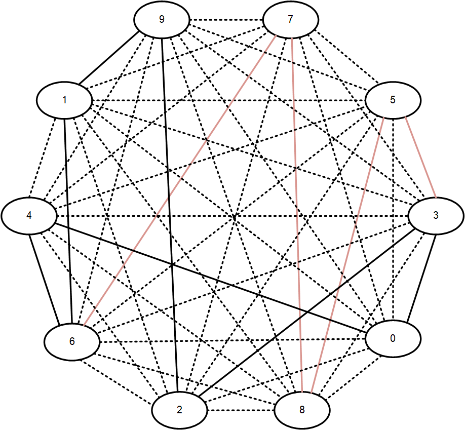
A flooding topology on a dense graph. The flooding topology is shown by the solid lines. Dotted lines indicate non-flooding links.
In a dense topology, this can reduce the amount of flooding by an order of magnitude or more, with a resulting increase in scalability.
EOS provides TWAMP support as a protocol used for active network performance monitoring. It measures the end-to-end performance of a network path by sending and receiving packets between two network devices. Previously, you could statically configure the minimum and maximum link delay, but with the addition of TWAMP, EOS supports dynamic measurement of link delay as described in RFC8186 and provides it to the IS-IS FlexAlgo dynamically.
The two modes operate independently, and the same interface can be in Active mode and Reflector mode simultaneously. To avoid conflict, configure different UDP ports for each mode.
IS-IS advertises the unidirectional link delay (the average delay), unidirectional min-max delay, and unidirectional delay variation measured by TWAMP Light. Only the unidirectional min-max delay advertises in Application Specific Link Attributes Sub-TLV (ASLA).
This feature only supports IPv4 probe packets, but EOS utilizes the measured link-delay values for IPv4 and IPv6 topologies in IS-IS multi-topology deployments.
EOS supports this feature on the following platforms:
The platforms must have at least one Femtocell Access Point (FAP) with the Revision of Q2c2TX. To verify the FAP revision, use the following command:
switch# show platform fap
Switches currently in the system

Name       Type           Device          Revision
---------- -------------- --------------- --------------
Fap0 Jericho2 Jericho2c Q2c2tA1 The switch supports only one IS-IS routing instance per VRF. The routing instance uniquely identifies the switch to other devices. IS-IS configuration commands apply globally to the IS-IS instance.
The switch must be in router IS-IS configuration mode to run IS-IS configuration commands. The router isis command places the switch in router IS-IS configuration mode.
Example
switch(config)# router isis Osiris
switch(config-router-isis)#After creating an IS-IS routing instance, configure the Network Entity Title (NET) with the net command. The NET defines the IS-IS area address and the system ID of the device.
Example
switch(config)# router isis Osiris
switch(config-router-isis)# net 49.0001.1010.1040.1030.00The address-family command enables the address families that IS-IS will route and places the switch in the configuration mode for that address family. The address families supported are IPv4 unicast and IPv6 unicast.
Example
switch(config)# router isis Osiris
switch(config-router-isis)# address-family ipv4 unicast
switch(config-router-isis-af)#After enabling IS-IS globally, enable it on an interface with the isis enable command.
Example
switch(config-router-isis)# interface ethernet 4
switch(config-if-Eth4)#isis enable OsirisThe is-type command sets the routing level for an IS-IS instance.
Example
switch(config)# router isis Osiris
switch(config-router-isis)# is-type level-2
switch(config-router-isis)#The redistribute (IS-IS) command configures redistribution of connected or static non-ISIS routes.
Example
switch(config)# router isis Osiris
switch(config-router-isis)# redistribute connected
switch(config-router-isis)#Non-ISIS routes can be exported into Level-1, Level-2, or both using a route map. By default, the routes are exported only to Level-2; to export to Level-1 or to both levels, configure the route map using the set isis level command. The Level-1 or Level-2 routes can also be filtered using the route maps match statement. The route map is then used when redistributing routes in ISIS with the redistribute (IS-IS) command.
Use the show isis database detail command to make sure that the route shows up in the exported level.
switch(config)# route-map rm
switch(config-route-map-rm)# set isis level level-1
switch(config-route-map-rm)# router isis osiris
switch(config-router-isis)# redistribute connected route-map rm
switch(config-router-isis)#switch# show isis database detail
ISIS Instance: inst1 VRF: default
ISIS Level 1 Link State Database
LSPID Seq Num Cksum Life IS Flags
1111.1111.1001.00-00 10 63306 751 L2 <>
NLPID: 0xCC(IPv4) 0x8E(IPv6)
Area address: 49.0001
<-------OUTPUT OMITTED FROM EXAMPLE-------->The redistribute bgp route-map command redistributes the BGP routes from the specified route map into IS-IS. Only one route map can be specified; reissuing the command overrides any previous configuration.
The no redistribute bgp and default redistribute bgp commands disable BGP route redistribution from the specified domain by removing the redistribute bgp statement from running-config.
The command is available in both router IS-IS configuration mode and the address-family submode. The command is rejected if configured in both modes at the same time. Issuing the no or default command in router IS-IS configuration mode has no effect on redistribution configured in the address-family submode.
switch(config)# router isis 1
switch(config-router-isis)# address-family ipv4
switch(config-router-isis-af)# redistribute bgp route-map bgp-to-isis-v4
switch(config-router-isis-af)#switch(config)# router isis 1
switch(config-router-isis)# redistribute bgp route-map bgp-to-isisThe overload bit is set in link state packets (LSPs) to signal that the switch is not available for forwarding transit traffic (for instance, during startup or when the switch is being taken down for maintenance). To set the overload bit manually, use the set-overload-bit command without the on-startup option. To configure the switch to set the overload bit after a reboot, allowing routing protocols to converge before the switch is used for forwarding traffic, use the set-overload-bit command with the on-startup option. The overload bit will remain set for the interval specified after startup.
In scenarios when Border Gateway Protocol (BGP) routes are resolved using an Interior Gateway Protocol (IGP), if the transit router reboots and becomes available again, the IGP will consider the transit router as an optimal path again. After rebooting, the transit router will blackhole traffic until the transit router learns the external destination reachability information via BGP.
These commands configure the switch to set the overload bit in LSPs sent for 120 seconds after startup.
switch(config)# router isis Osiris
switch(config-router-isis)# set-overload-bit on-startup 120
switch(config-router-isis)#switch(config)# router isis Osiris
switch(config-router-isis)# set-overload-bit on-startup wait-for-bgp
switch(config-router-isis)# set-overload-bit on-startup wait-for-bgp timeout 750
switch(config-router-isis)#To configure authentication for the IS-IS instance causing LSPs, CSNPs, and PSNPs to be authenticated, use the authentication mode and authentication key commands. To configure authentication on the interface, causing IS-IS Hellos to be authenticated, use the isis authentication mode and isis authentication key commands on the interface.
Two forms of authentication are supported by the IS-IS routing protocol: Clear-text authentication and MD5 authentication. The difference between the two forms of authentication is in the level of security provided. In the case of clear-text authentication, the password is specified as text in the authentication TLV, making it possible for an attacker to break authentication by sniffing and capturing IS-IS PDUs on the network. Arista recommends using the MD5 authentication.
HMAC MD5 authentication provides much stronger authentication by computing the message digest (on the IS-IS PDU contents) using the secret key to produce a hashed message authentication code (HMAC). Different modes of authentication can be specified on the interface, which authenticates IIH PDUs (IS-IS hello PDUs), and globally in the router IS-IS mode, in which the LSPs, CSNPs and PSNPs are authenticated. Area-wide and domain-wide authentication can be specified for L1 and L2 routers respectively.
switch(config)# router isis 1
switch(config-router-isis)# authentication mode md5
switch(config-router-isis)# authentication key secret
switch(config-router-isis)#switch(config)# interface Ethernet 3/6
switch(config-if-Et3/6)# isis authentication mode text
switch(config-if-Et3/6)# isis authentication key 7 cAm28+9a/xPi04o7hjd8Jw==
switch(config-if-Et3/6)#To maximize interoperability, Arista recommends using the same key in both interface mode and in the router isis mode.
Example
This command configures maximum wait interval, initial wait interval, and hold time to 10 seconds, 2000 ms, and 1000 ms respectively.
switch(config)# router isis inst1
switch(config-router-isis)# spf-interval 10 2000 1000IS-IS Segment Routing (SR) supports global adjacency SIDs for point-to-point interfaces. The adjacency SID is configured as an index using the adjacency-segment command.
Global adjacency segments are represented using an index instead of actual MPLS labels. The index is an offset into the Segment Routing Global Block (SRGB) advertised by a router, resulting in an MPLS label. The default value of SRGB in EOS is Base: 900000 and Size: 65536.
The same index may be used to configure multiple interfaces so that MPLS forms an ECMP group, and the same index may be applied to IPv4 and IPv6 adjacencies.
Example
switch(config-if-Et1)# adjacency-segment ipv4 p2p index 10 globalThe command show isis segment-routing adjacency-segments displays the global adjacency SID value and other related information.
switch(config)# interface ethernet 1/1
switch(config-if-Et1/1)# ip address 1.1.1.1/24
switch(config-if-Et1/1)# ipv6 address 1000::1/64
switch(config-if-Et1/1)# isis enable isis1
switch(config-if-Et1/1)# isis network point-to-point
switch(config-if-Et1/1)# adjacency-segment ipv4 p2p index 1 global
switch(config-if-Et1/1)# adjacency-segment ipv6 p2p index 2 globalswitch# show isis segment-routing adjacency-segments
System ID: 1000.0000.0002 Instance: isis1
SR supported Data-plane: MPLS SR Router ID: 1.1.1.4
Adj-SID allocation mode: SR-adjacencies
Adj-SID allocation pool: Base: 100000 Size: 16384
Adjacency Segment Count: 2
Flag Descriptions: F: Ipv6 address family, B: Backup, V: Value
L: Local, S: Set
Segment Status codes: L1 - Level-1 adjacency, L2 - Level-2 adjacency, P2P -
Point-to-Point adjacency, LAN - Broadcast adjacency
Locally Originated Adjacency Segments
Adj IP Address Local Intf SID SID Source Flags Type
----------------- ---------- ------ ----------- --------------- -------
1.1.1.2 Et1 1 Configured F:0 B:0 V:0 L:0 S:0 P2P L1
fe80::1:ff:fe65:0 Et1 2 Configured F:1 B:0 V:0 L:0 S:0 P2P L1
Received Global Adjacency Segments
SID Originator Neighbor Flags
--------- -------------------- ---------------- ---------
0 rtrmpls1 1000.0000.0002 F:0 B:0 V:0 L:0 S:0The log-adjacency-changes (IS-IS) command configures the switch to send syslog messages when it detects IS-IS neighbor adjacency state changes.
Example
switch(config)# router isis Osiris
switch(config-router-isis)# log-adjacency-changes
switch(config-router-isis)#The is-hostname command configures the use of a human-readable string to represent the symbolic name of an IS-IS router. It also changes the output of IS-IS show commands, to show the IS-IS hostname in place of system IDs if the corresponding IS-IS hostname is known. However, Syslogs still use IS-IS system IDs and not the IS-IS hostname.
By default if there's a hostname configured on the switch, it is used as the IS-IS hostname. It is also possible to de-configure an assigned hostname for IS-IS using the no is-hostname command. When the IS-IS hostname is removed, the switch goes back to using the switch's hostname as the IS-IS hostname.
switch(config)# router isis inst1
switch(config-router-isis)# is-hostname ishost1
switch(config-router-isis)#switch(config)# router isis inst1
switch(config-router-isis)# no is-hostname ishost1
switch(config-router-isis)#The multi-topology command configures IS-IS Multi-Topology (MT) support (disabled by default), enabling an IS-IS router to compute a separate topology for IPv4 and IPv6 links in the network. With MT configured, not all the links in a network need to support both IPv4 and IPv6. Some can support IPv4 or IPv6 individually. The IPv4 SPF will install IPv4 routes using the IPv4 topology, and similarly, the IPv6 SPF will install IPv6 routes using the IPv6 topology. Without MT support, all links in an IS-IS network need to support the same set of address families.
When MT is enabled, and each link has a separate IPv4 metric and IPv6 metric.
The isis ipv6 metric command configures the IPv6 metric.
The isis multi-topology command configures the IPv4 or IPv6 address family individually on an interface with both IPv4 and IPv6 addresses.
The address families that are enabled on an interface are based on the global address families enabled in router IS-IS configuration mode, and the addresses configured on the interface. To enable a particular address family on an interface, it needs to have an address configured in that address family. In the case where both IPv4 and IPv6 address families are enabled in router IS-IS configuration mode, then if an interface has IPv4 and IPv6 addresses, both IPv4 and IPv6 address families are enabled on that interface. In the case of an interface with only an IPv4 address family, the IPv4 address family is enabled on that interface. Where an interface only has an IPv6 address family, the IPv6 address family is enabled on that interface. Finally, where only the IPv6 address family is enabled in router IS-IS config mode and MT is enabled, then the IPv6 address family is enabled on all interfaces which have an IPv6 address configured.
switch(config)# router isis 1
switch(config-router-isis)# address-family ipv6 unicast
switch(config-router-isis-af)# multi-topology
switch(config-router-isis-af)#switch(config)# router isis 1
switch(config-router-isis)# address-family ipv6 unicast
switch(config-router-isis-af)# no multi-topology
switch(config-router-isis-af)#switch(config)# interface Ethernet 5/6
switch(config-if-Et5/6)# isis ipv6 metric 30
switch(config-if-Et5/6)#switch(config)# interface Ethernet1
switch(config-if-Et1)# isis multi-topology address-family ipv4 unicast
switch(config-if-Et1)#switch(config)# interface Ethernet1
switch(config-if-Et1)# isis multi-topology address-family ipv6 unicast
switch(config-if-Et1)#switch(config)# interface Ethernet1
switch(config-if-Et1)# no isis multi-topology address-family unicast
switch(config-if-Et1)#The isis hello-interval command sets the time interval between the hello packets that maintain an IS-IS adjacency.
Example
switch(config)# interface ethernet 4
switch(config-if-Et4)# isis hello-interval 60
switch(config-if-Et4)#The switch maintains the adjacency by sending/receiving hello packets. When receiving no hello packets from the peer within a time interval, the local switch considers the neighbors invalid.
The isis hello-multiplier command calculates the hold time announced in hello packets by multiplying this number with the configured isis hello-interval.
Example
switch(config)# interface ethernet 4
switch(config-if-Et4)# isis hello-interval 60
switch(config-if-Et4)# isis hello-multiplier 5
switch(config-if-Et4)#The isis metric command sets the cost for sending information over a specific interface. At present only wide metrics are supported.
Example
These commands configure a metric cost of 30 for sending information over interface ethernet 5.
switch(config)# interface ethernet 5
switch(config-if-Et5)# isis metric 30
switch(config-if-Et5)#The isis lsp tx interval command configures the minimum interval between successive LSP transmissions on an interface.
Example
switch(config)# interface ethernet 5
switch(config-if-Et5)# isis lsp tx interval 50
switch(config-if-Et5)#The isis priority command determines which device will be the Designated Intermediate System (DIS). The device with the highest priority on the LAN will become the DIS.
Example
switch(config)# interface ethernet 5
switch(config-if-Et5)# isis priority 60
switch(config-if-Et5)#A passive IS-IS interface does not send or receive IS-IS packets and will not form adjacencies, but is still included in LSP advertisements, making its IP address visible to the IS-IS domain. To configure an IS-IS interface as passive, use the isis passive command in interface configuration mode or the passive (IS-IS) command in router IS-IS configuration mode.
switch(config)# interface ethernet 10
switch(config-if-Etl0)# isis passive
switch(config-if-Etl0)#switch(config)# router isis Osiris
switch(config-router-isis)# passive ethernet 10
switch(config-router-isis)#The isis bfd and bfd all-interfaces commands configure Bidirectional Forwarding Detection (BFD). BFD is supported for both IS-IS IPv4 and IPv6 routes.
switch(config)# router isis 1
switch(config-router-isis)# address-family ipv4
switch(config-router-af)# bfd all-interfaces
switch(config-router-af)#switch(config)# interface Ethernet 5/6
switch(config-if-Et5/6)# isis bfd
switch(config-if-Et5/6)#IS-IS BFD Damping prevents a switch from establishing IS-IS adjacency on a link that experiences frequent BFD flapping. This feature mitigates SPF churn and reduces the computational load on the system by ensuring link stability before forming a neighbor relationship.
When BFD signals a DOWN state, IS-IS immediately removes the
adjacency, and recurring IP forwarding failures on a link result in adjacency flaps
on IS-IS. After enabling BFD Damping, IS-IS requires BFD to remain stable in the
UP state for a specified duration before attempting
to form an adjacency with the neighboring device.
0 for the initial interval.Configure all intervals in seconds, and ensure that the initial and hold interval values do not exceed the maximum damping interval. EOS disables the feature by default and supports only Point-to-Point (P2P) interfaces.
UP, and expects BFD to remain stable in the
UP state for the duration of the timer
before forming an adjacency.UP state through the
damping timer and finally establishes adjacency, the next BFD flap restarts
the damping timer for the hold interval.BFD IPv4 and IPv6 flaps can be monitored by configuring BFD Damping for both address families. In this case, the damping timers run independently for IPv4 and IPv6. Adjacency occurs only if the BFD state remains stable corresponding to the configured set of damping intervals, and neither damping timer has started.
If the adjacency currently has an UP status and BFD Damping needs
to be enabled, first configure IS-IS BFD, and wait for BFD to become active. Then,
configure BFD Damping for both address families.
If you need to configure new damping intervals while the corresponding damping timer runs, IS-IS immediately stops the damping timer. The new intervals apply to the subsequent BFD flaps.
When enabling BFD Damping on an interface, BFD-enabled TLV (Type 148) advertise in the
IS-IS Hello PDUs (IIH). Even though IS-IS exchanges IIH packets with the link, IS-IS
does not form the adjacency if the link does not have a BFD session with an
UP status.
When IS-IS undergoes a graceful restart, EOS establishes the adjacencies regardless of the BFD state, and damping timers do not initiate. After exiting the graceful restart, IS-IS monitors the BFD flaps and applies BFD Damping if configured.
switch(config)# router isis isis-4
switch(config-router-isis)# address-family ipv4
switch(config-router-af)# bfd all-interfaces wait-for-up damping-interval initial 0
hold 3 max 15To disable BFD Damping, use the no version of the command:
switch(config-router-af)# no bfd all-interfacesApply BFD Damping to specific IS-IS interfaces using the following commands:
switch(config)# interface Ethernet1
switch(config-if-Et1)# isis bfd wait-for-up damping-interface initial 0 hold 3 max 15To disable BFD Damping on an interface, use the following commands:
switch(config)# interface Ethernet1
switch(config-if-Et1)# no isis bfdThe interface IS-IS BFD Damping feature configuration overrides the corresponding global address-family configuration. However, if you set the interface configuration as default isis bfd, then the global address family configuration applies.
The show isis interface command displays the configured BFD Damping intervals for each address family on an IS-IS interface.
switch# show isis interface Et1
IS-IS Instance: isis-4 VRF: default
Interface Ethernet1:
...
BFD IPv4 damping is enabled Damping intervals - Initial: 0s, Hold: 3s, Max: 15s
BFD IPv6 damping is enabled Damping intervals - Initial: 0s, Hold: 1s, Max: 5s
...UP
state in order to form the adjacency.UP
before establishing the adjacency.switch# show isis neighbors detail
Instance VRF System Id Type Interface SNPA State Hold time Circuit Id
1 default ip2 L2 Ethernet1 P2P INIT 28 0A
...
BFD IPv4 wait-for-up is enabled
BFD IPv6 wait-for-up is enabled
Neighbor BFD IPv4 wait-for-up is enabled
Neighbor BFD IPv6 wait-for-up is enabled
BFD IPv4 damping is active Adjacency is waiting for BFD IPv4 to remain up
Damping timer: expires in 7 s at 2025-6-29 21:58:30
BFD IPv6 damping is active
Adjacency is waiting for BFD IPv6 to remain up
Damping timer: expires in 2 s at 2025-6-29 21:58:25While IS-IS waits for BFD to remain in the UP state, the
adjacency state on the local and neighbor device displays
INIT. After BFD becomes active, the adjacency state on
both IS-IS devices transitions to UP status.
EOS implements IS-IS LSP Out Delay to mitigate transient micro-loops that may occur during topology changes. By strategically delaying the flooding of routing updates, the switch ensures that all nodes in the network converge in a predictable sequence.
When topology changes occur, such as a link state or metric change, different routers in the network receive and process the updated Link State PDUs (LSPs) at slightly different times which leads to a transient state on the network. Some routers update the Forwarding Information Base (FIB) based on new LSPs, and other routers do not update the FIB, which causes traffic to forward incorrectly and form micro-loops.
Configuring the LSP Out Delay feature forces a router to pause before flooding self-originated LSPs after a link or metric decrease event. By delaying the advertisement, the local router completes the Shortest Path First (SPF) calculation and FIB update before the peer routers receive the LSP and recalculate the paths.
Use the following commands to configure the LSP Out Delay feature on switch, ISIS-4, 5000 milliseconds:
switch(config)# router isis ISIS-4
switch(config-router-isis)# timers lsp out-delay 5000
switch(config-router-isis)#Configure the same out-delay value for each end of a link (peers).
For a link-up event, the out-delay timer starts only after establishing adjacency with the peer.
For a metric decrease, the out-delay timer starts immediately after the metric change and defers the advertisement with the updated metric.
The IS-IS Multiple Router Capability TLVs Advertisement feature addresses a critical scalability bottleneck in segment-routed networks. It enables EOS to generate, advertise, and process multiple Router Capability TLVs (Type 242) within IS-IS Link State PDUs (LSPs).
remoteloc, use the following
commands:switch(config)# router isis remoteloc
switch(config-router-isis)# tlv multi-part
switch(config-router-isis-tlv-mp)# codepoint router-cap
switch(config-router-isis-tlv-mp)#switch(config)# router isis remoteloc
switch(config-router-isis)# tlv multi-part
switch(config-router-isis-tlv-mp)# no codepoint router-cap
switch(config-router-isis-tlv-mp)Global IS-IS Segment Routing (IS-IS SR) commands are accessed in Segment-Routing MPLS mode, under the router IS-IS configuration mode. Interface-specific IS-IS SR commands are accessed in interface configuration mode.
The Routing Information Base (RIB) or IS-IS agent provides IS-IS segment routing, but the actual installation of LFIB entries pertaining to SR information provided by IS-IS is handled by the MPLS agent in EOS, which is disabled by default. To enable the MPLS agent, use the following commands.
Example
switch(config)# ip routing
switch(config)# mpls ip
switch(config)#By default, IS-IS SR is disabled. You must enable it explicitly by issuing the no form of the shutdown (IS-IS SR) command in Segment-Routing MPLS configuration mode.
Example
switch(config)# router isis instance1
switch(config-router-isis)# segment-routing mpls
switch(config-router-isis-sr-mpls)# no shutdown
switch(config-router-isis-sr-mpls)#To administratively disable IS-IS SR, issue the shutdown (IS-IS SR) command in Segment-Routing MPLS configuration mode. To disable isis sr and delete all isis sr configuration, issue the segment-routing mpls command in router isis configuration mode.
Examples
switch(config)# router isis instance1
switch(config-router-isis)# segment-routing mpls
switch(config-router-isis-sr-mpls)# shutdown
switch(config-router-isis-sr-mpls)#switch(config)# router isis instance1
switch(config-router-isis)# no segment-routing mpls
switch(config-router-isis)#The global segments such as Prefix-SID, Node-SID, Proxy-node-SID are represented using indices of actual MPLS labels. These indices are offset on the SRGB advertised by a router to derive the respective MPLS label. The default value of SRGB in EOS is Base: 900000, Size: 65536. In other words, the labels that any global segment could represent is between 900000-965535. The MPLS label range is categorized and reserved into pools based on the applications using these labels. The default values of label ranges in these pools are:
switch(config)# mpls label range isis-sr 900000 65536The IS-IS maximum LSP size provides the ability to configure the maximum LSP size that the IS-IS protocol accepts and sends. The default value of LSP size is 9000. The lsp size maximum command configures maximum size of an LSP that is sent or received. The default LSP maximum size is 9000. The minimum value is 512.
switch(config)# lsp size maximum 400switch(config)# no lsp size maximumswitch(config)# default lsp size maximumNode segments are indices associated with routers within an IS-IS SR domain by associating node segments with prefix mask length /32 (IPV4) or /128 (IPV6) addresses. Node segments are carried as sub-TLVs (type-length-value) in IP reachability TLVs for the prefixes with the associated segments. Node segments can also be represented by an absolute label and validated against the default or user-specific SRGV advertised by a router. An Absolute Node-SID has a label range of 16 - 1048575.
A node segment label or Absolute Node SID represents a global segment validated based on the ISIS-SR global block, such as an SRGB range configured with the mpls label range isis-sr base range. Node segment label or Absolute Node SID advertise as an index and bases the in-label on the local SRGB range and the out-label on the peer SRGB range.
switch(config)# int loopback 1
switch(config-if-Lo1)# ip address 21.1.1.1/32
switch(config-if-Lo1)# node-segment ipv4 index 5switch(config)# int loopback 1
switch(config-if-Lo1)# ipv6 add 2000::24/128
switch(config-if-Lo1)# node-segment ipv6 index 6switch(config)# int loopback 1
switch(config-if-Lo1)# ip address 21.1.1.1/24
switch(config-if-Lo1)# node-segment ipv4 index 1
! /32 IPv4 address is not configured on the interfaceswitch(config-if-Lo1)# node-segment ipv4 label 900123switch(config-if-Lo1)# show node-segment ipv4 label 900123switch(config-if-Lo1)# no node-segment ipv4 index 1Node segments can be configured with either an explicit-null or no-php flag as well as a specific algorithm. The following example shows how to add the two flag parameters:
switch(config-if-Lo1)# node-segment ipv4 index 1 ?
explicit-null Set Explicit Null flag
flex-algo Flexible algorithm
no-php Set No-PHP flag
switch(config-if-Lo1)# node-segment ipv4 index 1 explicit-null
switch(config-if-Lo1)# node-segment ipv6 index 2 no-php
switch(config-if-Lo1)# node-segment ipv4 index 3 flex-algo Algo-128
switch(config-if-Lo1)# show active
interface Loopback1
ip address 31.1.1.1/32
ipv6 address 2000::24/128
node-segment ipv4 index 1 explicit-null
node-segment ipv4 index 3 flex-algo Algo-128
node-segment ipv6 index 2 no-phpThe CLI returns a warning if no /32 or /128 IPv4 addresses exist on the interface, but accepts the configuration anyway.
switch(config-if-Lo2)# ip address 33.2.2.1/24
switch(config-if-Lo2)# node-segment ipv4 index 33
! /32 IPv4 address is not configured on the interface
switch(config-if-Lo2)# show active
interface Loopback2
ip address 33.2.2.1/24
node-segment ipv4 index 33
switch(config-if-Lo2)# node-segment ipv6 index 34
! /128 IPv6 address is not configured on the interface
switch(config-if-Lo2)# show active
interface Loopback2
ip address 33.2.2.1/24
node-segment ipv4 index 33
node-segment ipv6 index 34
switch(config-if-Lo2)# ip address 33.2.2.1/24
switch(config-if-Lo2)# node-segment ipv4 label 96123
! /32 IPv4 address is not configured on the interface
switch(config-if-Lo2)# show active
interface Loopback2
ip address 33.2.2.1/24
node-segment ipv4 label 61234
switch(config-if-Lo2)# node-segment ipv6 label 64321
! /128 IPv6 address is not configured on the interface
switch(config-if-Lo2)# show active
interface Loopback2
ip address 33.2.2.1/24
node-segment ipv4 index 33
node-segment ipv6 index 34Remove node segments from IS-IS using the no parameter under the node-segment parameter for an interface.
switch(config-if-Lo2)# no node-segment ipv4 index 33switch(config-if-Lo2)# no node-segment ipv4 label 900123A router originating an IP reachability TLV associates Prefix segments with any IS-IS. These segments are carried as sub-TLVs in IP Reachability TLVs of the prefixes with which these segments are associated. Prefix segments are configured under segment-routing MPLS configuration mode in IS-IS.
Example
switch(config)# router isis instance1
switch(config-router-isis)# segment-routing mpls
switch(config-router-isis-sr-mpls)# prefix-segment 1.1.1.0/24 index 50Node segments represent a device (node) by attaching a segment (index) with a /32, /128 prefix which generally is configured on a loopback interface. For routers that do not support segment routing, you must assign node identifiers on such routers. In this instance, a router that supports IS-IS SR to proxy by configuring a proxy-node-SID for an IS-IS prefix originating from the router that does not support IS-IS SR.
Example
switch(config)# router isis instance1
switch(config-router-isis)# segment-routing mpls
switch(config-router-isis-sr-mpls)# proxy-node-segment 1.1.1.0/32 index 50In general, configure a proxy node segment on a router without the prefix that you want to associate with the proxy-node SID. You can also configure one for self-originated prefixes.
Configuring proxy-node-SIDs enables a router to send out a Binding-SID TLV with details pertaining to the prefix and SID.
The default hop behavior of an Arista switch removes the top label if a neighbor node advertises reachability. Change this behavior for Proxy-Node segments using the attached parameter.
When routes redistribute from other domains into an IS-IS SR domain on a node, other nodes assume the prefixes directly connect to the node advertising reachability. This may not be the case and causes incorrect penultimate hop popping (PHP) behavior.
Using the attached flag corrects the behavior, and setting the flag on a proxy-node segment directly connected to the node advertising reachability. Verify the attached flag configuration using the show isis segment-routing prefix-segments command.
switch(config-router-isis-sr-mpls)# show isis segment-routing prefix-segments
System ID: 0000.0000.5555 Instance: 'inst1'
SR supported Data-plane: MPLS SR Router ID: 5.5.5.5
Node: 5 Proxy-Node: 3 Prefix: 0 Total Segments: 8
Flag Descriptions: R: Re-advertised, N: Node Segment, P: no-PHP
E: Explicit-NULL, `V: Value, L: Local
Segment status codes: * - Self originated Prefix, L1 - level 1, L2 - level 2, ! - SR-unreachable,
# - Some IS-IS next-hops are SR-unreachable
Prefix SID Type Flags System ID Level Protection Algorithm
------------------- ----- ---------- --------------------------- --------------- ----- ----------- ----------
* 5.5.5.5/32 5 Proxy-Node R:0 N:0 P:0 E:0 V:0 L:0 A:0 0000.0000.5555 L2 unprotected SPF
* 6.6.6.6/32 6 Proxy-Node R:0 N:0 P:0 E:0 V:0 L:0 A:0 0000.0000.5555 L2 unprotected SPF
* 44.44.44.44/32 44 Proxy-Node R:0 N:0 P:0 E:0 V:0 L:0 A:1 0000.0000.5555 L2 unprotected SPFConfigure a second parameter, attached-flag inspect and enable it on all nodes. When set, the behavior defaults to no-php, the penultimate hop swaps or forwards the label, for all proxy node segments without the attached set.
switch(config)# router isis inst1
switch(config-router-isis)# segment-routing mpls
switch(config-router-isis-sr-mpls)# proxy-node-segment attached-flag inspect44.44.44.44/32 on penultimate node
R3.5.5.5.5/32 and
6.6.6.6/32 without the attached flag on R3.4.4.4.4/32 on R4 as the penultimate LDP
hop.By default, EOS does not allow conflicts between proxy-node segments and other types of segments such as Node or Prefix. To ignore conflicts, use the conflict ignore keyword when configuring proxy-nodes.
Example
The following configuration uses the conflict ignore keyword:
switch(config-router-isis-sr-mpls)#proxy-node-segment 1.0.14.1/32 index 200 range 10 conflict ignoreAn Anycast-SID is a prefix segment that identifies a set of routers and not a specific router. It enforces the ECMP-aware shortest-path forwarding towards the closest node of the anycast set.
An example of such an anycast group could be a set of routers A1, A2, A3, and A4 where at least one router of A1, A2, A3, and A4 advertises the prefix SID corresponding to the anycast address (which can be a prefix originating on all of A1, A2, A3 and A4 a loop-back address, maybe).
In general use case, all the routers of the anycast group would have the same prefix-SID configured for the anycast IP address present on them.
A router that support IS-IS SR need to advertise its SR data-plane capability and the range of MPLS label values it uses for segment routing, this is advertised by inserting SR-Capability sub-TLV in the Router Capabilities TLV.
A Router Capability TLV is now sent in IS-IS LSPs when Segment routing is enabled and it is necessary for a Router Capability TLV to carry a router-ID. This router-ID could be configured in EOS under the segment routing MPLS configuration mode. If no router-ID is configured, the router automatically picks up the highest IPv4 address configured on the router for an router-ID.
Adjacency segments for IS-IS adjacencies are statically configured on the switch, so that these values are preserved even when the switch restarts. Static adjacency segments are configured per address family on any interface (including Port-Channel, VLANs and SVIs). They are configured and advertised as labels.
Example
switch(config-if-Et1)# adjacency-segment ipv4 p2p index 50 globalThey can be a label (local) or index (global) and we can assign multiple adjacency segments per link.
Where label-value must be within the SR Local Block (SRLB) that can be found in the output of show mpls label range command as shown.
switch# show mpls label range
Start End Size Usage
------------------------------------------------
0 15 16 reserved
16 99999 99984 static mpls
100000 362143 262144 free (dynamic)
362144 899999 537856 unassigned
900000 965535 65536 isis-sr
900000 965535 65536 bgp-sr
965536 1031071 65536 srlb
1031072 1036287 5216 unassigned
1036288 1048575 12288 l2evpnAdjacency Segments are MPLS labels assigned to IS-IS adjacencies.These labels are shared with other routers in the domain by adding them in adjacency-SID sub-TLVs which are inserted in neighbor Reachability TLVs in IS-IS.
The MPLS labels (adjacency segments) are incrementally allocated to adjacencies, as the transition to Up state, from a adjacent set of MPLS labels pre-allocated by MPLS agent. This label range extends from 100000 to 116383 (base: 100000, size: 16384) by default. This could be changed by the following configuration:
Example
switch(config)# mpls label range dynamic 200000 131072The dynamic label pool is shared between LDP and IS-IS SR Adjacency Segments.
Adjacency Segments are allocated to all IS-IS adjacencies based on the IS-IS routers that have advertised IS-IS SR capability or to none of the adjacencies. The command adjacency-segment allocation is used to configure this under the segment-routing mpls configuration mode.
The default behavior is to allocate adjacency segments to adjacencies of SR supporting devices.
Example
switch(config-router-isis-sr-mpls)# adjacency-segment allocation sr-peerAdjacency segments are allocated to IS-IS adjacencies based on configured adjacency segment allocation mode mentioned above.
If an adjacency that has been allocated label L goes down, L is reserved for this adjacency for a duration of 3600 seconds from the time of the adjacency down event. Only the adjacency that owned this label before going down could reclaim label L in this duration.
For a given prefix, if both a proxy-node segment and prefix-SID are received, the prefix-SID advertised is preferred while the proxy-node segment is ignored.
The show tech-support ribd displays detail information about IS-IS SRs internal state, and more information on conflicts and chosen active segments could be found under the SR Book Keeper section of show tech-support ribd command as shown.
Received Prefix Segments:
------------------------------------------------------------------
Prefix | Value | Index/Label | Type | SystemID | spfgen
* - Active, # - Duplicate pfx, + - duplicate SID
-------------------------------------------------------------------
*1.0.3.0/24 3 Index Prefix 1111.1111.1002 0
*1.0.5.1/32 0 Index Node 1111.1111.1002 0
*1.0.6.1/32 2 Index Node 1111.1111.1003 39
*1.0.7.1/32 14 Index Node 1111.1111.1001 39
#1.0.7.1/3210 Index Proxy 1111.1111.1003 39
Refer to Segment Routing Over IPv6 (SRv6) for an overview of terminology used for SRv6.
Configure the Flex Algorithm constraints in the Flex-Algo Configuration Mode in the Traffic-Engineering router feature:
switch(config)# router traffic-engineering
switch(config-te)# flex-algo
switch(config-te-flex-algo)# flex-algo 128 algoRed
switch(config-te-flex-algo-def-algoRed)# metric te-metric
switch(config-te-flex-algo-def-algoRed)# administrative-group exclude Red
switch(config-te-flex-algo-def-algoRed)#instance_1, network entity
49.0001.1111.1111.111.00. and Flex-Algo
algoRed
:switch(config)# router isis instance_1
switch(config-router-isis)# net 49.0001.1111.1111.1111.00
switch(config-router-isis)# is-type level-1
switch(config-router-isis)# flex-algo definition algoRed
switch(config-router-isis)# address-family ipv6 unicast
switch(config-router-isis-af)# srv6
switch(config-router-isis-af-srv6)# flex-algo algoRed
switch(config-router-isis-af-srv6)#LOC1 with an appropriate
domain block, and usid value, add the domain
and locator parameters in the VRF Default Configuration Mode in the Segment-Routing
Configuration Mode. The Flex-Algo name, for example ,algoRed
associates a locator with a flex algorithm using the following
commands:switch(config)# router srv6
switch(config-srv6)# vrf default
switch(config-router-srv6-vrf-default)# local address 2001:db8:100::1
switch(config-router-srv6-vrf-default)# micro-segment domain DOM1
switch(config-router-srv6-vrf-default-domain)# block fc00:42::/32
switch(config-router-srv6-vrf-default-domain)# exit
switch(config-router-srv6-vrf-default)# micro-segment domain DOMRed
switch(config-router-srv6-vrf-default-domain)# block fc00:80::/32
switch(config-router-srv6-vrf-default-domain)# exit
switch(config-router-srv6-vrf-default)# locator LOC1
switch(config-router-srv6-vrf-default-locator)# prefix micro-segment domain DOM1 end usid 1
switch(config-router-srv6-vrf-default-locator)# exit
switch(config-router-srv6-vrf-default)# locator LOCRed
switch(config-router-srv6-vrf-default-locator)# prefix micro-segment domain DOMRed end usid 1
switch(config-router-srv6-vrf-default-locator)# igp algorithm flex-algo algoRed
switch(config-router-srv6-vrf-default-locator)To advertise the locally configured Node Adjacency uSIDs in IS-IS Link State Packets (LSPs), enable the locator in the SRV6 Configuration Mode of IS-IS.
switch(config)# router isis instance_1
switch(config-router-isis)# net 49.0001.1111.1111.1111.00
switch(config-router-isis)# is-type level-1
switch(config-router-isis)# address family ipv6 unicast
switch(config-router-isis-af)# srv6
switch(config-router-isis-af-srv6)# locator LOC1
switch(config-router-isis-af-srv6)# locator LOCRed
switch(config-router-isis-af-srv6)#Configure advertising for adjacency SIDs (uSIDs) on an interface using the following commands:
switch(config)# interface Ethernet 1/1
switch(config-if-Et1/1)# isis enable instance_1
switch(config-if-Et1/1)# isis network point-to-point
switch(config-if-Et1/1)# adjacency-segment srv6 locator LOC1 usid 60398 behavior end.x p2p link-local
switch(config-if-Et1/1)# adjacency-segment srv6 locator LOCRed usid 60398 behavior end.x p2p link-localThis topic contains the following sections:
Use the following commands to display information about SRv6 configurations in IS-IS.
isis srv6
locators detail
command:switch# isis srv6 locators detail
Locator: fc00:42:1::/48
System ID: 1111.1111.1111
Flags: Down: unset
Level: 1
Algorithm: SPF (0), Topology: 0
Locator: fc00:80:1::/48
System ID: 1111.1111.1111
Flags: Down: unset
Level: 1
Algorithm: algoRed (128), Topology: 0Use the show isis database detail to display information about the SRv6 Locators advertised by all nodes in the network:
switch# show isis database detail
IS-IS Instance: instance_1 VRF: default
IS-IS Level 1 Link State Database
LSPID Seq Num Cksum Life Length IS Received LSPID Flags
1111.1111.1111.00-00 4 22289 1052 175 L1 1111.1111.1111.00-00 <>
LSP received time: 2025-11-18 04:22:53
Remaining lifetime received: 1199 s Modified to: 1200 s
NLPID: 0x8E(IPv6)
Hostname: R3-tpn465
Area addresses: 49.0001
...
SRv6 Locator: fc00:42:1::/48 Topology: 0
Metric: 10 Algorithm: 0 Flags: []
SRv6 SID End with NEXT-CSID PSP USD
SID : fc00:42:1::
SID structure: Block length: 32 Node length: 16
Function length: 0 Argument length: 0
SRv6 Locator: fc00:80:1::/48 Topology: 0
Metric: 10 Algorithm: 128 Flags: []
SRv6 SID End with NEXT-CSID PSP USD
SID : fc00:80:1::
SID structure: Block length: 32 Node length: 16
Function length: 16 Argument length: 0
Router Capabilities: Router Id: 10.0.12.1 Flags: []
Area leader priority: 250 algorithm: 0
SRv6 Capability: Flags: []
Algorithms: 0, 128
Flex Algo: Algorithm: 128 Metric: TE Metric (2) Calc: SPF (0) Prio: 237
Exclude admin groups: 1
IS Neighbor : 6401.0000.011b.00 Metric: 10
SRv6 SID End.X with PSP USP
Flags: [] Algorithm: 0 Weight: 0
SID: fc00:42:1:ebee::
SID structure: Block length: 32 Node length: 16
Function length: 16 Argument length: 0
SRv6 SID End.X with PSP USP
Flags: [P] Algorithm: 128 Weight: 0
SID: fc00:80:1:ebee::
SID structure: Block length: 32 Node length: 16
Function length: 16 Argument length: 0
Use the show isis database detail tlv to display information about the SRv6 Locators advertised by all nodes in the network:
switch# show isis database detail tlv
IS-IS Instance: 1 VRF: default
IS-IS Level 2 Link State Database
LSPID Seq Num Cksum Life Length IS Received LSPID Flags
1111.1111.1111.00-00 531 4209 53443 862 L2 1111.1111.1111.00-00 <>
LSP received time: 2026-05-06 19:52:45
Remaining lifetime received: 65534 s Modified to: 65535 s
...
SRv6 Locator TLV #27, length: 86
SRv6 Locator: fc00:42:1::/48 Topology: 0
Metric: 10 Algorithm: 0 Flags: []
SRv6 End SID sub-TLV #5, length: 26
SRv6 SID End with NEXT-CSID PSP USD
SID fc00:42:1::
SRv6 SID Structure sub-sub-TLV #1, length: 4
SID structure: Block length: 32 Node length: 16
Function length: 0 Argument length: 0
SRv6 Locator: fc00:80:1::/48 Topology: 0
Metric: 10 Algorithm: 128 Flags: []
SRv6 End SID sub-TLV #5, length: 26
SRv6 SID End with NEXT-CSID PSP USD
SID fc00:42:1::
SRv6 SID Structure sub-sub-TLV #1, length: 4
SID structure: Block length: 32 Node length: 16
Function length: 0 Argument length: 0
...
IS-IS Router Capability TLV #242, length: 131
Router Capabilities: Router Id: 1.1.1.1 Flags: []
Segment Routing Algorithm sub-TLV #19, length: 4
Algorithms: 0, 128
SRv6 Capabilities sub-TLV #25, length: 2
SRv6 Capability: Flags: []
Flexible Algorithm Definition (FAD) sub-TLV #26, length: 70
Flex Algo: Algorithm: 129 Metric: TE Metric (2) Calc: SPF (0) Prio: 237
IS-IS Flexible Algorithm Exclude Admin Group sub-sub-TLV #1, length: 64
Exclude admin groups: 1switch# show isis flex-algo path
Flex algo paths for IPv6 address family
Topology ID: Level-1
Destination Algorithm Next Hop Interface
-------------------- --------------- -------------------------- ---------
fc00:42:1::/48 SPF fe80::200:3ff:fe02:0 Ethernet1
fc00:80:1::/48 algoRed fe80::200:3ff:fe02:0 Ethernet1Adding the parameter details displays more information about the computed paths:
switch# show isis flex-algo path detail
Destination: fc00:42:1::/48
Path ID: 4480
Path constraints: algo SPF
metric type TE
administrative-group exclude Red(1)
Request sequence number: 0
Response sequence number: 0
Number of times path updated: 3
Last updated: 7 days, 2:06:28 ago
Metric: 20
Next Hop Interface
-------------------- ---------
fe80::200:3ff:fe02:0 Ethernet1Other routers in the IS-IS also have routes installed for the locator prefix. Use the show ipv6 route command:
switch# show ipv6 route
I L1 fc00:42:1::/48 [115/30]
via fe80::200:3ff:fe02:0, Ethernet1
I L1 fc00:80:1::/48 [115/30]
via fe80::200:3ff:fe02:0, Ethernet1switch# show tunnel rib brief
Tunnel RIB: system-tunnel-rib
Endpoint Tunnel Type Index(es) Tunnel Preference IGP Preference IGP Metric Metric Type
------------------------- ----------------- --------------- ----------------------- -------------------- ---------------- -----------
fc00:42:1::/128 IS-IS SRv6 2 65 115 20 metric
fc00:80:1::/128 IS-IS SRv6 3 65 115 20 metricThe output indicates that for BGP routes with the next hop fc00:42:1:: the resolved route contains the IS-IS SRv6 tunnel with index 2 similar to the Flex-Algo route.
2 to the
command:switch# show tunnel fib isis srv6 2
Type 'IS-IS SRv6', index 2, endpoint fc00:42:1::/128, algorithm algo128, forwarding None
via fe80::200:3ff:fe02:0, 'Ethernet1' SRv6, source 2001:db8:200::8, SRv6 sid-list fc00:42:1::The redistribute dhcp command redistributes DHCPv6 routes in IS-IS when using multi-agent routing protocol mode.
switch(config)# router isis 1
switch(config-router-isis)# address-family ipv6
switch(config-router-isis-af)# redistribute dhcp
switch(config-router-isis-af)#switch(config)# show isis database detail
IS-IS Instance: inst1 VRF: default
IS-IS Level 1 Link State Database
LSPID Seq Num Cksum Life IS Flags
1111.1111.1001.00-00 10 19778 1101 L1 <>
...
Reachability (MT-IPv6): 3ffe:701:ffff:101::10/128 Metric: 0 Type: 1 Up
...An IS-IS instance can be shut down globally or can be disabled on individual interfaces.
The shutdown (IS-IS) command shuts down an IS-IS instance globally.
Example
switch(config)# router isis Osiris
switch(config-router-isis)# shutdown
switch(config-router-isis)#The no isis enable command disables IS-IS on an interface.
Example
switch(config-router-isis)# interface ethernet 4
switch(config-if-Eth4)# no isis enableBy default, IS-IS graceful restart is disabled. Use the graceful-restart command to configure graceful restart on an IS-IS router. By default IS-IS graceful-restart-helper functionality is enabled, and to disable it use no graceful-restart-helper command.
Examples
switch(config)# router isis 1
switch(config-router-isis)# graceful-restart t2 level-1 30t2 is the maximum wait time for the LSP database to synchronize (SPF computation is not done while t2 is running). t2 can be configured for either Level-1 or Level-2 through the CLI. The default value is 30 seconds, and the allowed configuration range is 5 to 300 seconds.
Example
switch(config)# router isis 1
switch(config-router-isis)# graceful-restart restart-hold-time 50In case of a planned restart, the hold time advertised by the IS-IS router prior to restart should be greater than the time for which the router is expected to be offline. Otherwise, neighboring routers will bring down the adjacency before the restarting router has a chance to send a restart request in its hello packet, which may result in traffic loss.
In case of ASU2, the IS-IS router instance will advertise a hello hold time of restart-hold-time on those interfaces for which the configured hold time is less than restart-hold-time. This is done just before the router restarts.
For Graceful Restart to be successful, the hold time advertised by the router should be greater than the time it takes for Graceful Restart to complete. If the restarting router is DIS, hold time advertised is 1/3rd of the configured value (default is 9s). We recommend increasing the hold time for the DIS to a higher value before a planned restart; otherwise, it may result in traffic loss.
EOS advertises IS-IS passive and active interfaces, but in some cases, you want to control the Time-to-Liveadvertisement of interface addresses on the switch. Configure IS-IS to advertise only passive interfaces and control the LSP size by stopping the advertisement of active interfaces and reduce the IS-IS convergence time in complex networks.
EOS supports advertise ip-reachability passive-only to control the advertisement of IP Reachability TLVs. When enabled, IS-IS advertises IP Reachability for passive interfaces only.
Configuring IS-IS Interface Advertisement and Reachability
Use the following command to advertise TLVs from only passive interfaces on IS-IS instance, inst1:
switch(config)#router isis inst1
switch(config-router-isis)#advertise interface-address passive-onlyUse the following command to advertise reachability TLVs from only passive interfaces on IS-IS instance, inst1:
switch(config)#router isis inst1
switch(config-router-isis)#advertise ip-reachability passive-onlyDisplaying IS-IS Interface Advertisement Information
Use the following command to display information about IS-IS Interface Advertisement:
switch#show running-config
...
router isis inst1
net 49.0001.1111.1111.1001.00
is-hostname A
is-type level-2
lsp purge origination-identification
log-adjacency-changes
advertise interface-address passive-only
advertise ip-reachability passive-only
!
address-family ipv4 unicast
…To implement minimum-delay and maximum-delay in the IS-IS FlexAlgo, configure a TWAMP sender profile, and select it when adding a traffic engineering configuration.
switch(config)#monitor twamp
switch(config-monitor-twamp)#twamp-light
switch(config-twamp-light)#Configure the sender profile parameters as follows:
switch(config-twamp-light)#sender profile MyTWAMPprofile
switch(config-twamp-light-sender-profile-MyTWAMPprofile)#measurement interval 10 seconds
switch(config-twamp-light-sender-profile-MyTWAMPprofile)#measurement samples 5
switch(config-twamp-light-sender-profile-MyTWAMPprofile)#significance 10 microseconds offset 5 microsecondsThe ceiling function computes the ceiling values by adding the offset value to multiples of the significance value starting from a multiple of 0. For example, if you specify a significance of ten (10) and the offset as three (3), then the ceiling values compute as 3, 13, 23, 33, etc. The measured delay rounds up to the nearest ceiling value greater than the measure delay.
Configure the UDP ports for sending and reflecting TWAMP probes by setting the listen port, source port, and destination port. The reflector uses the listen port to listen for incoming packets. The sender uses the source port and destination port in probe packets.
Configure the ports using the following commands:
switch(config-twamp-light)#reflector defaults
switch(config-twamp-light-reflector-defaults)#listen port 51201
switch(config-twamp-light-reflector-defaults)#exit
switch(config-twamp-light)#sender defaults
switch(config-twamp-light-sender-defaults)#destination port 51201
switch(config-twamp-light-sender-defaults)#source port 51200Configure traffic engineering for IGP (IS-IS) to use the dynamic unidirectional delay of the point-to-point links as measured by the TWAMP Light sender profile.
Global Configuration
Activate the TWAMP sender profile globally using the following commands:
switch(config)#router traffic-engineering
switch(config-te)#twamp-light sender profile MyTWAMPprofile
Per Interface Configuration
Activate the TWAMP sender profile on an interface using the following commands:
switch(config)#interface Ethernet 3
switch(config-if-Et3)#traffic-engineering twamp-light sender profile MyTWAMPprofileActivate TWAMP measurements and use measured values for traffic engineering on an interface using the following command:
switch(config-if-Et3)#traffic-engineering min-delay dynamic twamp-light fallback value microseconds/millisecondsA fallback value must be configured on all IS-IS interfaces using dynamic delay measurement. IS-IS advertises this fallback value if TWAMP Light fails to compute the dynamic unidirectional minimum delay metric of a link.
The show monitor twamp-light command displays the calculated one way and two way minimum delay. Be default, all information displays for all peer IP addresses configured on the remote end of the IS-IS point-to-point links. You can also filter for a specific IP address.
switch#show monitor twamp-light
Unit: microseconds
IP Address Interface One Way Two Way
Minimum Delay Minimum Delay
------------ ------------ --------------- ---------------
1.0.0.2 Ethernet17/1 2742 5482
1.0.0.3 Ethernet18/1 2772 5544
switch#show monitor twamp-light ip 1.0.0.2
Unit: microseconds
IP Address Interface One Way Two Way
Minimum Delay Minimum Delay
------------ ------------ --------------- ---------------
1.0.0.2 Ethernet17/1 2742 5482Use the show monitor twamp-light detail to display detailed information about calculated results. By default, it displays information for all IP addresses configured on the remote end of the IS-IS point-to-point links or filter on a specific IP address.
switch#show monitor twamp-light detail ip 1.0.0.2 detail
IP address: 1.0.0.2
Interface: Ethernet17/1
Description: Interface Ethernet17/1
Sender profile name: defaultSender
Effective sampling rate: 1 packet every 1.0 second
Packets sent: 178
Packets received: 21
Unit: microseconds
Measurement Min Max Avg Variance
------------- ---- ------ ----- ----------
One-way delay 2742 236072 19822 4294967295
Two-way delay 5482 472132 39642 4294967295The following configuration tasks can be performed by Topology Independent Fast Reroute (TI-LFA FRR) using IS-IS Segment-Routing.
To enable link or node protection for node segments and Adjacency segments learned on a specific IS-IS interface, use the following command in the interface configuration mode.
switch(config-if-Et1)# [no|default] isis fast-reroute ti-lfa mode {link-protection|node-protection|disabled} [level-1|level-2]The interface TI-LFA configuration inherits the address-family sub-mode configuration by default.
On an L1-L2 router, the [level-1|level-2] optional keyword in both the router IS-IS address-family sub-mode and interface configuration mode CLIs is used to restrict protection to node segments and Adjacency segments learned through either Level-1 or Level-2 topologies only.
The Point of Local Repair (PLR) switches to the TI-LFA backup path on link failure or BFD neighbor failure but switches back to the post-convergence path once the PLR computes SPF and updates its LFIB. This sequence of events can lead to micro-loops in the topology if the PLR converges faster than other routers along the post-convergence path. So a configuration option is provided to apply a delay, after which the LFIB route being protected by the TI-LFA loop-free repair path will be replaced by the post-convergence LFIB route.
To configure a convergence delay only to LFIB routes that are being protected, the following command is used either in the router IS-IS mode or the router isis address-family sub-mode. A default of 10 seconds is used when using the command without an explicitly specified delay.
timers local-convergence-delay [delay_in_milliseconds] protected-prefixesThe PLR computes backup paths for an adjacency segment only if the Adjacency SID sub-TLV has the B-flag (backup flag) set.
To set the B-flag in originated Adjacency SID sub-TLVs corresponding to adjacency segments dynamically allocated on the router, the following command is used in the segment-routing mpls sub-mode in the router isis mode.
adjacency-segment allocation [all-interfaces | sr-peers]adjacency-segment [ipv4 | ipv6] p2p [multiple][label label | index index] backup-eligiblebackup-eligible is the newly introduced optional keyword in both the CLIs mentioned above that controls the setting of the B-flag in the Adjacency SID sub-TLV.
To enable SRLG protection on all interfaces, use the fast-reroute ti-lfa srlg command. This command is used in addition to configuring link-protection or node-protection. If SRLG protection is enabled, the backup paths are computed after excluding all the links that share the same SRLG with the active link that is being used by all prefix segments and adjacency segments.
If the optional argument strict is configured, the backup path is only programmed if a backup path that excludes all the SRLGs configured on the primary interface. If the keyword is not provided and an SRLG excluding path is not available, TI-LFA programs the backup path that excluded the maximum number of SRLGs possible.
isis [ipv4 | ipv6] fast-reroute ti-lfa srlg disabledSample Configuration
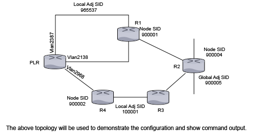
The above topology is used to demonstrate the configuration and show command output. You will see the backup paths that the PLR computes to protect the node segments of R1 and R2, the global adjacency segment on R2, and the local adjacency segment on the vlan 2387 on the PLR.
Here is a snippet of the configuration on the PLR.
switch(config)# interface vlan 2138
switch(config-if-Vl2138)# ip address 10.1.1.1/24
switch(config-if-Vl2138)# isis enable inst1
switch(config-if-Vl2138)# isis metric 11
switch(config-if-Vl2138)# isis network point-to-point
switch(config)# interface vlan2387
switch(config-if-Vl2138)# ip address 10.1.2.1/24
switch(config-if-Vl2138)# isis enable inst1
switch(config-if-Vl2138)# isis network point-to-point
switch(config-if-Vl2138)# adjacency-segment ipv4 p2p label 965537 backup-eligible
switch(config)# interface vlan2968
switch(config-if-Vl2968)# ip address 10.1.3.1/24
switch(config-if-Vl2968)# isis enable inst1
switch(config-if-Vl2968)# isis network point-to-point
switch(config-if-Vl2968)# isis fast-reroute ti-lfa mode disabled
…
switch(config)# router isis inst1
switch(config-isis)# net 49.0001.1111.1111.1001.00
switch(config-isis)# router-id ipv4 252.252.1.252
switch(config-isis)# is-type level-2
switch(config-isis)# timers local-convergence-delay 5000 protected-prefixes
!
switch(config-isis)# address-family ipv4 unicast
switch(config-isis-af)# fast-reroute ti-lfa mode node-protection
!
switch(config-isis)# segment-routing mpls
switch(config-isis-sr-mpls)# no shutdown
switch(config-isis-sr-mpls)# adjacency-segment allocation sr-peers backup-eligible
!
endThe protection of anycast segments does not need any new configuration. The above configuration enables protection of anycast segments.
To demonstrate the protection of anycast segments consider the following topology.
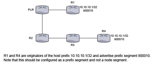
R1 and R4 are originators of the host prefix 10.10.10.1/32 and advertise prefix segment 900010. This must be configured as a prefix segment and not a node segment.
R1 and R4’s configuration should look similar to the following:
switch(confg)# router isis inst1
switch(config-router-isis)# interface Loopback0
switch(config-if-Lo0)# ip address 10.10.10.1/32
switch(config-if-Lo0)# isis enable inst1
!
...
switch(confg)# router isis inst1
switch(config-router-isis)# segment-routing mpls
switch(config-router-isis-sr-mpls)# prefix-segment 10.10.10.1/32 index 10
!The prefix in the prefix-segment command must belong to an interface enabled with IS-IS or must be an active route in the RIB of another protocol redistributed into IS-IS.
When the link or node protection is configured on the PLR, then the primary path to the segment 900010 is PLR - R1 and the backup path is PLR - R2 - R3 - R4. In other words, the destination in the backup path is the segment originated by R4 as the segment originated by R1 and is not reachable when link PLR-R1 or the node R1 goes down.
When services like LDP pseudowires, BGP LU, L2 EVPN, or L3 MPLS VPN use IS-IS SR tunnels as an underlay, these services are automatically protected by TI-LFA tunnels that protect the IS-IS SR tunnels. The show ip route command displays the hierarchy of the overlay-underlay-TI-LFA tunnels.
switch# show ip route
B 2001:db8:3::/48 [200/0]
via 2002::b00:301/128, IS-IS SR tunnel index 3, label 122697
via TI-LFA tunnel index 5, label imp-null(3)
via fe80::200:76ff:fe03:0, Ethernet26/1, label imp-null(3)
backup via fe80::200:76ff:fe01:0, Ethernet30/1, label 900002 900003switch(config)# router isis Amun
switch(config-router-isis)# net 49.0000.0000.3333.00
switch(config-router-isis)# is-hostname ip3
switch(config-router-isis)# lsp flooding dynamiclsp flooding dynamic [level-1 | level-2]
nolsp flooding dynamic [level-1 | level-2]
default lsp flooding dynamic [level-1 | level-2]If necessary, the area leader election process can be tuned or disabled with these commands:
area leader [level-1 | level-2] priority 0-255 area leader [level-1 | level-2] disabled
no area leader [level-1 | level-2] priority 0-255 area leader [level-1 | level-2] disableddefault area leader [level-1 | level-2] priority 0-255 area leader [level-1 | level-2] disabledOn a sparse topology, Dynamic Flooding is not effective and only adds overhead. Leaf-spine and Clos networks are appropriate dense topologies.
In Arista EOS, IS-IS Fast Flooding accelerates the convergence of the Link State Database (LSDB) in large or dense networks. Standard IS-IS flooding rates use static intervals between Link State PDUs (LSPs) which can be too slow for high-performance networks with thousands of nodes or adjacencies.
IS-IS Fast Flooding allows a router to flood LSPs at much higher rates by negotiating flooding capabilities with neighbors. The feature uses Sub-TLVs, Burst Size and Transmission Interval, signaled in IS-IS Hello packets to inform neighbors exactly how many LSPs the switch can process in a burst and the minimum delay required between those bursts.
You must enable fast flooding on the local and peer link of the IS-IS adjacency to activate it. Once enabled, IS-IS Hello packets exchange EOS flooding parameters, and fast flooding activates on the adjacency.
Use the following commands to configure a fast flooding profile, FF_receiver1, the following parameters:
switch(config)# router isis F1
switch(config-router-isis)# fast-flooding profile FF_receiver
switch(config-router-isis-fast-flooding)# lsp burst size 30
switch(config-router-isis-fast-flooding)# lsp receiver window size 50
switch(config-router-isis-fast-flooding)# lsp lsp tx interval 20
switch(config-router-isis-fast-flooding)# psnp tx 100
switch(config-router-isis-fast-flooding)# psnp lpp count 40
switch(config-router-isis-fast-flooding)#To enable fast flooding on an interface, apply the configured fast flooding profile to the IS-IS instance or on the interface.
Use the following commands to apply the fast flooding profile, FF_receiver1, on the IS-IS instance, FF2:
switch(config)# router isis FF2
switch(config-router-isis)# fast-flooding all-interfaces profile FF_receiver1
switch(config-router-isis)# The configuration applies to all interfaces in the IS-IS instance.
Use the following commands to apply the fast flooding profile, FF_receiver1, to Ethernet interface, Ethernet 1:
switch(config)# interface Ethernet1
switch(config-if-Et1)# isis fast-flooding profile FF_receiver1
switch(config-if-Et1)Use the show isis interface command to display if fast
flooding is enabled or disabled in Ethernet1.
switch# show isis interface Ethernet3
IS-IS Instance: inst1 VRF: default
Interface Ethernet3:
Index: 20 SNPA: P2P
MTU: 1497 Type: point-to-point
Supported address families: IPv4
Area proxy boundary is disabled
Speed: 10000 mbps
BFD IPv4 is disabled
BFD IPv6 is disabled
Hello padding is enabled
Local fast flooding is enabled
Level 2:
Metric: 10, Number of adjacencies: 1
Link-ID: 14
Authentication mode: None
TI-LFA protection is disabled for IPv4
TI-LFA protection is disabled for IPv6Address-Family Check for IS-IS creates the adjacency between devices with different address families. For example, a router supporting IPv4 and IPv6 is connected to a IPv4 only router, Address-Family Check is verified by comparing the NLPID TLV ( Type #129 ) advertised in IIH hellos exchanged between peers. It is useful in following scenarios.
Relaxing the Address-Family Check is useful to gradually add IPv6 support in an IPv4 network, without disturbing the IPv4 connectivity.
A controller forms an IS-IS adjacency with a router and uses the IS-IS database for topology discovery. If the controller only supports IPv4 IS-IS or only IPv4 tunnels, to relax the Address-Family Check on the dual stack IPv4/v6 router for adjacency is useful in establishment.
Under IS-IS instance, configure the following to disable the Address-Family Check during IIH processing.
switch(config-router-isis)# ?
adjacency Configure parameters for adjacency formation
switch(config-router-isis)# adjacency?
address-family Configure address-family related parameters for adjacency formation
switch(config-router-isis)# adjacency address-family?
match Configure address-family match check related parameters for adjacency formation
switch(config-router-isis)# adjacency address-family match?
disabled Relax address-family match check for bringing up adjacency
switch(config-router-isis)# adjacency address-family match disabled?switch# show isis neighbor detail
Instance VRF System Id Type Interface SNPA State Hold time Circuit Id
inst1 default 1111.1111.1002 L2 Vlan2116 P2P UP 24 06
Area Address(es): 49.0001
SNPA: P2P
Router ID: 1.0.0.2
Advertised Hold Time: 30
State Changed: 00:04:18 ago at 2020-11-01 22:28:35
IPv4 Interface Address: 1.0.0.2
IPv6 Interface Address: none
Interface name: Vlan2116
Graceful Restart: Supported
Segment Routing Enabled
SRGB Base: 900000 Range: 65536
Adjacency Label IPv4: 149152
Supported Address Families: IPv4, IPv6
Neighbor Supported Address Families: IPv4switch(config-router-isis)# show isis interface detail
IS-IS Instance: inst1 VRF: default
Interface Vlan2116:
Index: 35 SNPA: P2P
MTU: 1497 Type: point-to-point
Supported Address Families: IPv4, IPv4
Area Proxy Boundary is Disabled
BFD IPv4 is Disabled
BFD IPv6 is Disabled
Hello Padding is Enabled
Level 2:
Metric: 10, Number of adjacencies: 1
Link-ID: 23
Authentication mode: None
TI-LFA link protection is enabled for the following IPv4 segments: node segments, adjacency segments
TI-LFA protection is disabled for IPv6
Adjacency 1111.1111.1002:
State: UP, Level: 2 Type: Level 2 IS
Advertised Hold Time: 30
Neighbor Supported Address Families: IPv4
Address Family Match: Disabled
IPv4 Interface Address: 1.0.0.2
Areas:
49.0001For IPv6 network upgrade, ensure the knob is incrementally configured on a contiguous section of the network, at any point the choice of routers for upgrade should not bisect the upgraded (supporting IPv4/v6) part of the network. All the routers bordering the upgraded network should always have the knob enabled.
EOS stores changes to IS-IS routes into a SQL database to assist with troubleshooting convergence issues and understanding the impact changes have on a switch. When an IS-IS route changes due to a IS-IS SPF calculation, Event Monitoring stores the changes and tracks the time of the changes.
The SQL database stores the following information for each event:
Add_Or_Update or Delete messagesRib - Specifies the time for a candidate route to update as computed by IS-IS.SwFib - Specifies the time for the computed winning route in software to update.HwFib - Specifies the time that the route sends to the forwarding hardware. All platforms support the Rib and SwFib layers.
HwFib:
Use the following commands to configure Event Monitoring for IS-IS:
switch(config)# event-monitor convergence
switch(config-event-mon-conv)# vrf default
switch(config-event-mon-conv-vrf-default)# event route convergence protocol isis
switch(config-event-mon-conv-vrf-default)#Displaying Raw Event Data
Use the following command to display raw event data:
switch# show event-monitor sqlite select * from IpRouteChange
2025-12-02 13:55:17.585097|2000:0:0:41::/64|Add_Or_Update|Rib|default
2025-12-02 13:55:17.585211|1.0.1.0/24|Add_Or_Update|Rib|default
2025-12-02 13:55:17.586671|2000:0:0:41::/64|Add_Or_Update|SwFib|default
2025-12-02 13:55:17.587460|1.0.1.0/24|Add_Or_Update|SwFib|default
2025-12-02 13:55:17.616044|2000:0:0:41::/64|Add_Or_Update|HwFib|default
2025-12-02 13:55:17.650337|1.0.1.0/24|Add_Or_Update|HwFib|default
2025-12-02 14:01:23.235124|1.0.1.0/24|Delete|Rib|default
2025-12-02 14:01:23.237152|1.0.1.0/24|Delete|SwFib|default
2025-12-02 14:01:23.241243|1.0.1.0/24|Delete|HwFib|defaultIn the example output, the IP addresses, 1.0.1.0/24 and
2000:0:0:41::/64, move through three layers in rapid succession.
Then deletes IP address 1.0.1.0/24.
To display the link state database of IS-IS, use the show isis database command.
Example
switch# show isis database
ISIS Instance: Osiris
ISIS Level 2 Link State Database
LSPID Seq Num Cksum Life IS Flags
1212.1212.1212.00-00 4 714 1064 L2 <>
1212.1212.1212.0a-00 1 57417 1064 L2 <>
2222.2222.2222.00-00 6 15323 1116 L2 <>
2727.2727.2727.00-00 10 15596 1050 L2 <>
3030.3030.3030.00-00 12 62023 1104 L2 <>
3030.3030.3030.c7-00 4 53510 1104 L2 <>
switch>To display interface information related to the IS-IS instance, use the show isis interface command.
Example
switch# show isis interface
ISIS Instance: Osiris
Interface Vlan20:
Index: 59 SNPA: 0:1c:73:c:5:7f
MTU: 1497 Type: broadcast
Level 2:
Metric: 10, Number of adjacencies: 2
LAN-ID: 1212.1212.1212, Priority: 64
DIS: 1212.1212.1212, DIS Priority: 64
Interface Ethernet30:
Index: 36 SNPA: 0:1c:73:c:5:7f
MTU: 1497 Type: broadcast
Level 2:
Metric: 10, Number of adjacencies: 1
LAN-ID: 3030.3030.3030, Priority: 64
DIS: 3030.3030.3030, DIS Priority: 64
switch>To display general information for IS-IS neighbors that the device sees, use show isis neighbors.
Example
switch# show isis neighbor
Inst Id System Id Type Interface SNPA State Hold time
10 2222.2222.2222 L2 Vlan20 2:1:0:c:0:0 UP 30
10 1212.1212.1212 L2 Vlan20 2:1:0:d:0:0 UP 9
10 3030.3030.3030 L2 Ethernet30 2:1:0:b:0:0 UP 9
switch>To display the system ID, Type, Interface, IP address, State and Hold information for IS-IS instances, use the show isis summary command. The command is also used to verify the configured maximum wait interval, initial wait interval, and hold time of SPF timers in IS-IS instances. This command also displays values of the current SPF interval, last Level-1 SPF run, and last Level-2 SPF run.
switch# show isis summary
ISIS Instance: Osiris
System ID: 1010.1040.1030, administratively enabled, attached
Internal Preference: Level 1: 115, Level 2: 115
External Preference: Level 1: 115, Level 2: 115
IS-Type: Level 2, Number active interfaces: 1
Routes IPv4 only
Last Level 2 SPF run 2:32 minutes ago
Area Addresses:
10.0001
level 2: number dis interfaces: 1, LSDB size: 1
switch>switch(config-router-isis-af)# show isis summary
IS-IS Instance: 1 VRF: default
System ID: 0000.0000.0001, administratively enabled
Multi Topology disabled, not attached
IPv4 Preference: Level 1: 115, Level 2: 115
IPv6 Preference: Level 1: 115, Level 2: 115
IS-Type: Level 1 and 2, Number active interfaces: 0
Routes both IPv4 and IPv6
Max wait(s) Initial wait(ms) Hold interval(ms)
LSP Generation Interval: 5 50 50
SPF Interval: 2 1000 1000
Current SPF hold interval(ms): Level 1: 1000, Level 2: 1000
Last Level 1 SPF run 1 seconds ago
Last Level 2 SPF run 1 seconds ago
Authentication mode: Level 1: None, Level 2: None
Graceful Restart: Disabled, Graceful Restart Helper: Enabled
Area Addresses:
49.0001
level 1: number dis interfaces: 0, LSDB size: 1
level 2: number dis interfaces: 0, LSDB size: 1Use the show isis database detail command to view the LSPDB of different devices in the IS-IS domain. The output displays the TLVs and sub-TLVs that are being self-originated or the ones that have been received from other routers.
Example
switch# show isis database detail
ISIS Instance: inst1 VRF: default
ISIS Level 2 Link State Database
LSPID Seq Num Cksum Life IS Flags
1111.1111.1001.00-00 10 63306 751 L2 <>
NLPID: 0xCC(IPv4) 0x8E(IPv6)
Area address: 49.0001
Interface address: 1.0.7.1
Interface address: 1.0.0.1
Interface address: 2000:0:0:47::1
Interface address: 2000:0:0:40::1
IS Neighbor : lf319.53 Metric: 10
LAN-Adj-sid: 100000 flags: [ L V ] weight: 0 system ID: 1111.1111.1002
IS Neighbor (MT-IPv6): lf319.53 Metric: 10
LAN-Adj-sid: 100001 flags: [ L V F ] weight: 0 system ID: 1111.1111.1002
Reachability : 1.0.11.0/24 Metric: 1 Type: 1 Up
SR Prefix-SID: 10 Flags: [ R ] Algorithm: 0
Reachability : 1.0.3.0/24 Metric: 1 Type: 1 Up
Reachability : 1.0.7.1/32 Metric: 10 Type: 1 Up
SR Prefix-SID: 2 Flags: [ N ] Algorithm: 0
Reachability : 1.0.0.0/24 Metric: 10 Type: 1 Up
Reachability (MT-IPv6): 2000:0:0:4b::/64 Metric: 1 Type: 1 Up
SR Prefix-SID: 11 Flags: [ R ] Algorithm: 0
Reachability (MT-IPv6): 2000:0:0:43::/64 Metric: 1 Type: 1 Up
Reachability (MT-IPv6): 2000:0:0:47::1/128 Metric: 10 Type: 1 Up
SR Prefix-SID: 3 Flags: [ N ] Algorithm: 0
Reachability (MT-IPv6): 2000:0:0:40::/64 Metric: 10 Type: 1 Up
Router Capabilities: 252.252.1.252 Flags: [ ]
SR Capability: Flags: [ I V ]
SRGB Base: 900000 Range: 65536
Segment Binding: Flags: [ F ] Weight: 0 Range: 1 Pfx 2000:0:0:4f::1/128
SR Prefix-SID: 19 Flags: [ ] Algorithm: 0
Segment Binding: Flags: [ ] Weight: 0 Range: 1 Pfx 1.0.15.1/32
SR Prefix-SID: 18 Flags: [ ] Algorithm: 0Use the show isis segment-routing command to display the summary information on IS-IS SR status.
Example
switch(config)# show isis segment-routing
System ID: 1111.1111.1002 Instance: inst1
SR supported Data-plane: MPLS SR Router ID: 252.252.2.252
SR Global Block( SRGB ): Base: 900000 Size: 65536
Adj-SID allocation mode: SR-adjacencies
Adj-SID allocation pool: Base: 100000 Size: 16384
All Prefix Segments have : P:0 E:0 V:0 L:0
All Adjacency Segments have : F:0 B:0 V:1 L:1 S:0
ISIS Reachability Algorithm : SPF (0)
Number of ISIS segment routing capable peers: 3
Self-Originated Segment Statistics:
Node-Segments : 2
Prefix-Segments : 2
Proxy-Node-Segments : 0
Adjacency Segments :About the Output
The first line of the output displays the IS-IS system ID of this device and the name of the instance with IS-IS configured.
The supported data plane is shown against the SR supported Data-plane field whereas the Router ID being advertised in the Router Capability is mentioned in the SR Router ID Field.
The SRGB in use and the MPLS label pool being used for adjacency segment allocation are mentioned in this output. The current adjacency allocation mode which refers to allocating adjacency segments to all IS-IS adjacencies or only those adjacencies which support SR or None of the adjacencies is shown in the Adj-SID allocation mode field.
Flag contents of All Prefix Segments originated on this router, Flag contents of All Adjacency Segments originated on this router and supported IS-IS Reachability Algorithm have been provided through this command output and they carry the meaning as per the IS-IS SR IETF draft.
This show command provides a statistics related to IS-IS SR in terms of various counters ranging from number of IS-IS SR enabled peers, number of Node-SIDs, prefix-SIDs, proxy-node-segments and adjacency segments being originated on this router in IS-IS.
The show isis segment-routing command also provides information if segment routing has been administratively disabled as shown.
switch(config-router-isis-sr-mpls)# show isis segment-routing
! IS-IS (Instance: inst1) Segment Routing has been administratively shutdownUse the show isis segment-routing global-blocks command to list the SRGBs in use by all SR supporting devices in IS-IS domain including the SRGB in use by IS-IS SR on this device.
Example
switch# show isis segment-routing global-blocks
System ID: 1111.1111.1002 Instance: inst1
SR supported Data-plane: MPLS SR Router ID: 252.252.2.252
SR Global Block( SRGB ): Base: 900000 Size: 65536
Number of ISIS segment routing capable peers: 3
SystemId Base Size
-------------------- ------------ -----
1111.1111.1002 900000 65536
1111.1111.1001 900000 65536Use the show isis segment-routing prefix-segments command to provide the details of all prefix segments being originated as well the segments received from IS-IS SR speakers in the domain.
Example
switch# show isis segment-routing prefix-segments
System ID: 1111.1111.1002 Instance: inst1
SR supported Data-plane: MPLS SR Router ID: 252.252.2.252
Node: 2 Proxy-Node: 2 Prefix: 2 Total Segments: 6
Flag Descriptions: R: Re-advertised, N: Node Segment, P: no-PHP
E: Explicit-NULL, V: Value, L: Local
Segment status codes: * - Self originated Prefix, L1 - level 1, L2 - level 2
Prefix SID Type Flags SystemID Type
--------------------- --------- ---------------- ---------------------
1.0.7.1/32 2 Node R:0 N:1 P:0 E:0 V:0 L:0 1111.1111.1001 L1
* 1.0.8.1/32 4 Node R:0 N:1 P:0 E:0 V:0 L:0 1111.1111.1002 L2
1.0.11.0/24 10 Prefix R:1 N:0 P:0 E:0 V:0 L:0 1111.1111.1001 L2
* 1.0.12.0/24 12 Prefix R:1 N:0 P:0 E:0 V:0 L:0 1111.1111.1002 L2
1.0.15.1/32 18 Proxy-Node R:0 N:0 P:0 E:0 V:0 L:0 1111.1111.1001 L2
1.0.16.1/32 20 Proxy-Node R:0 N:0 P:0 E:0 V:0 L:0 1111.1111.1003 L2About the Output
After the usual output header that represents the system ID, instance name, etc and parameters of a router, there is a line depicting prefix segment counters. Each field in this line relates to the number of segments that are present in this routers IS-IS instance. For example, the above example shows that this device has 2 Node Segments, self-originated as well as the ones received from other IS-IS SR devices.
The main section of this show commands output lists all the prefix segments and related information like prefix, SID, type of segment (Prefix, Node, Proxy-Node), the flag values being carried in the sub-TLVs of these prefix segments and the system ID of the originating router. The Type field will be useful on a IS type level-1-2 router. It shows whether the installed prefix segment is from a level-1 prefix or a level-2 prefix.
The show isis segment-routing prefix-segments self-originated command output is identical to show isis segment-routing prefix-segments except the former lists only self-originated prefix segments.
Use the show isis segment-routing adjacency-segments to display a list of all the adjacency segments originating by IS-IS SR on a router.
Example
switch# show isis segment-routing adjacency-segments
System ID: 1111.1111.1002 Instance: inst1
SR supported Data-plane: MPLS SR Router ID: 252.252.2.252
Adj-SID allocation mode: SR-adjacencies
Adj-SID allocation pool: Base: 100000 Size: 16384
Adjacency Segment Count: 4
Adj IP-address Local Intf Label SID Source Flags Type
----------------- -------- ------ ------ --- --------- --------- --------
1.0.0.1 Vlan2472 100000 Dynamic F:0 B:0 V:1 L:1 S:0 LAN L2
1.0.1.2 Vlan2579 100001 Dynamic F:0 B:0 V:1 L:1 S:0 P2P L2
fe80::1:ff:fe01:0 Vlan2472 100002 Dynamic F:0 B:0 V:1 L:1 S:0 LAN L2
fe80::1:ff:fe02:0 Vlan2579 100003 Dynamic F:0 B:0 V:1 L:1 S:0 P2P L2About the Output
It consists allocation mode, MPLS label pool from which labels would be allocated to adjacencies, total count of adjacency segments allocated so far and the default flag values carried in all adj-SID sub-TLVs originating from this device.
The main section of the output lists all the adjacency segments allocated so far in six columns each pertaining to Adjacency IP address, local interface name, MPLS label value, SID source, flags in the sub-TLV and the type of adj-SID respectively. The type of the adjacency segments depends on the IS-IS type of adjacency and the IS level.
Use the show mpls label ranges command to display the MPLS label range available on a router categorized into different pools that cater to different applications running on the router.
The isis-sr refers to the SRGB use-case in IS-IS, and isis
(dynamic) refers to the label pool used
for dynamic allocation of adjacency segments in IS-IS.
Example
switch# show mpls label ranges
Start End Size Usage
-----------------------------------------
0 15 16 reserved
16 99999 99984 static mpls
100000 116383 16384 isis (dynamic)
116384 362143 245760 free (dynamic)
362144 899999 537856 unassigned
900000 965535 65536 isis-srUse the show mpls segment-routing bindings command to display the local label bindings and label bindings on the peer routers for each prefix with a segment advertised. Peer ID here represents the IS-IS system ID of the peer.
Example
switch# show mpls segment-routing bindings
1.0.7.1/32
Local binding: Label: 900002
Remote binding: Peer ID: 1111.1111.1001, Label: imp-null
Remote binding: Peer ID: 1111.1111.1003, Label: 900002
1.0.8.1/32
Local binding: Label: imp-null
Remote binding: Peer ID: 1111.1111.1001, Label: 900004
Remote binding: Peer ID: 1111.1111.1003, Label: 900004
1.0.9.1/32
Local binding: Label: 900006
Remote binding: Peer ID: 1111.1111.1001, Label: 900006
Remote binding: Peer ID: 1111.1111.1003, Label: imp-nullUse the show mpls lfib route command to display the LFIB. Each LFIB entry has In-Label, Out-Label, metric, payload type, next-hop information, etc. fields. The source column depicts the MPLS control plane protocol responsible for the label binding that resulted in this LFIB route.
Example
switch# show mpls lfib route
MPLS forwarding table (Label [metric] Vias) - 7 routes
MPLS next-hop resolution allow default route: False
Via Type Codes:
M - Mpls Via, P - Pseudowire Via,
I - IP Lookup Via, V - Vlan Via,
VA - EVPN Vlan Aware Via, ES - EVPN Ethernet Segment Via,
VF - EVPN Vlan Flood Via, AF - EVPN Vlan Aware Flood Via,
NG - Nexthop Group Via
Source Codes:
S - Static MPLS Route, B2 - BGP L2 EVPN,
B3 - BGP L3 VPN, R - RSVP,
P - Pseudowire, L - LDP,
IP - IS-IS SR Prefix Segment, IA - IS-IS SR Adjacency Segment,
IL - IS-IS SR Segment to LDP, LI - LDP to IS-IS SR Segment,
BL - BGP LU, ST - SR TE Policy,
DE - Debug LFIB
IA 100000 [1]
via M, 1.0.1.2, pop
payload autoDecide, ttlMode uniform, apply egress-acl
interface Vlan2930
IA 100001 [1]
via M, fe80::200:eff:fe02:0, pop
payload autoDecide, ttlMode uniform, apply egress-acl
interface Vlan2930
IP 900008 [1]
via M, 1.0.1.2, swap 900008
payload autoDecide, ttlMode uniform, apply egress-acl
interface Vlan2930
IP 900009 [1]
via M, fe80::200:eff:fe02:0, swap 900009
payload autoDecide, ttlMode uniform, apply egress-acl
interface Vlan2930Use the show mpls lfib route <label value> command to provide information relevant to the label value passed as an extension to the show command.
Example
switch# show mpls lfib route 900008
MPLS forwarding table (Label [metric] Vias) - 7 routes
MPLS next-hop resolution allow default route: False
Via Type Codes:
M - Mpls Via, P - Pseudowire Via,
I - IP Lookup Via, V - Vlan Via,
VA - EVPN Vlan Aware Via, ES - EVPN Ethernet Segment Via,
VF - EVPN Vlan Flood Via, AF - EVPN Vlan Aware Flood Via,
NG - Nexthop Group Via
Source Codes:
S - Static MPLS Route, B2 - BGP L2 EVPN,
B3 - BGP L3 VPN, R - RSVP,
P - Pseudowire, L - LDP,
IP - IS-IS SR Prefix Segment, IA - IS-IS SR Adjacency Segment,
IL - IS-IS SR Segment to LDP, LI - LDP to IS-IS SR Segment,
BL - BGP LU, ST - SR TE Policy,
DE - Debug LFIB
IP 900008 [1]
via M, 1.0.1.2, swap 900008
payload autoDecide, ttlMode uniform, apply egress-acl
interface Vlan2930The show isis local-convergence-delay command shows the current or last attempt at delaying the convergence of protected routes on a link down/BFD neighbor down event. If the timer aborts for some reason (such as a topology change causing a new SPF), the attempt fails.
switch# show isis local-convergence-delay
IS-IS Instance: inst1 VRF: default
System ID: 1111.1111.1001
IPv4 local convergence delay configured, 5000 msecs
IPv6 local convergence delay configured, 5000 msecs
Level 1 attempts 0, failures 0
Level 2 attempts 3, failures 1
Level 2 in progress due to LINK DOWN on Vlan2138
TI-LFA node protection is enabled for IPv4
IPv4 Routes delayed: 0
Delay timer started at: 2019-07-25 23:16:33
Delay timer expires in 2 secs
TI-LFA protection is disabled for IPv6
Level 2 last attempt due to LINK DOWN on Vlan2138, Succeeded
TI-LFA node protection is enabled for IPv4
IPv4 Routes delayed: 3
Delay timer started at: 2019-07-25 23:14:51
Delay timer stopped at: 2019-07-25 23:14:56
TI-LFA protection is disabled for IPv6The detail keyword also lists all the routes that have been delayed.
switch# show isis local-convergence-delay detail
...
Level 2 last attempt due to LINK DOWN on Vlan2138, Succeeded
TI-LFA node protection is enabled for IPv4
IPv4 Routes delayed: 3
Delay timer started at: 2019-07-25 23:14:51
Delay timer stopped at: 2019-07-25 23:14:56
Delayed routes:
10.0.7.1/32
10.0.9.1/32
10.0.10.1/32
TI-LFA protection is disabled for IPv6switch# show isis graceful-restart vrf default
IS-IS Instance: 1 VRF: default
System ID: 0000.0000.0001
Graceful Restart: Enabled, Graceful Restart Helper: Enabled
State: Last Start exited after T2 (level-1) expiry
T1 : 3s
T2 (level-1) : 30s/20s remaining
T2 (level-2) : 30s/not running
T3 : not running
System ID Type Interface Restart Capable Status
is-hostname-1 L1L2 Ethernet1 Yes Running
is-hostname-2 L1 Ethernet2 Yes Restartingswitch# show isis summary vrf default
IS-IS Instance: 1 VRF: default
System ID: 0000.0000.0001, administratively enabled
....
Graceful Restart: Enabled, Graceful Restart Helper: Enabledswitch# show isis neighbors detail vrf default
Instance VRF System Id Type Interface SNPA State Hold time Circuit Id
1 default OT1 L1 Ethernet1 2:1:0:b 4:0:0 UP 29839 OT3.05
Area Address(es): 49.0001
SNPA: 2:1:0:b4:0:0
....
Graceful Restart: Supported, Status: Restarting (RR rcvd, RA sent, CSNP sent)switch# show isis interface detail vrf default
ISIS Instance: ISISQ VRF: default
Interface Ethernet1:
Index: 2 SNPA: P2P
...
Level 1:
Graceful Restart Status: RR sent, SA sent, RA rcvd, CSNP rcvdswitch# show isis dynamic flooding topology
IS-IS Instance: Amun VRF: default
Level 1:
Path: ip6.00 ip4.00 ip2.00 ip1.00 ip3.00 ip5.00 ip6.00This command displays a list of paths that describe the flooding topology. Each path is a list of nodes in the network.
switch# show isis dynamic flooding interfaces
IS-IS Instance: Amun VRF: default
Level 1:
Ethernet5
Ethernet4This shows that the system is currently flooding only on ethernet4 and ethernet5. Normally at least two interfaces are selected.
The address-family command places the switch in address-family configuration mode.
Address-family configuration mode is not a group change mode; running-config is changed immediately after commands are executed. The exit command does not affect the configuration.
The no address-family and default address-family commands delete the specified address-family from running-config by removing all commands previously configured in the corresponding address-family mode.
The exit command returns the switch to the isis configuration mode.
Command Mode
Router-IS-IS Configuration
Command Syntax
address-family [ipv4 | ipv6][MODE]
no address-family [ipv4 | ipv6][MODE]
default address-family [ipv4 | ipv6][MODE]
Parameters
switch(config)# router isis Osiris
switch(config-router-isis)# address-family ipv4 unicast
switch(config-router-isis-af)#switch(config)# router isis Osiris
switch(config-router-isis)# address-family ipv4 unicast
switch(config-router-isis-af)# exit
switch(config-router-isis)#Use the adjacency-segment command in the interface configuration mode to have the PLR computes backup paths for an adjacency segment only if the Adjacency SID sub-TLV has the B-flag (backup flag) set.
Command Mode
Interface configuration mode
Command Syntax
adjacency-segment [ipv4|ipv6] p2p [multiple][label label | indexindex] backup-eligible
no adjacency-segment [ipv4 | ipv6]p2p [multiple][label label|index index] backup-eligible
default adjacency-segment [ipv4 | ipv6]p2p multiple][label label|index index] backup-eligible
The adjacency-segment command allocates adjacency segments to all IS-IS adjacencies, or only those adjacencies which are to IS-IS routers that have advertised IS-IS SR capability, or to none of the adjacencies.
Command Mode
Segment-Routing MPLS Configuration
Command Syntax
adjacency-segment allocation [all-interface |none | sr-peers]
Parameters
Example
switch(config-router-isis-sr-mpls)# adjacency-segment allocation sr-peerThe adjacency-segment command configures IS-IS adjacencies statically on the switch, so that these values are preserved even when the switch restarts. The no and the default form of the command places the switch back to the global configuration mode.
Command Mode
Interface Ethernet Configuration
Command Syntax
adjacency-segment ipv4 | ipv6 p2p [[label label-value]|[index index-value global]]
Parameters
Example
switch(config-if-Et1)# adjacency-segment ipv4 p2p index 50 globalThe advertise interface-address passive-only command configures IS-IS to advertise interface addresses for passive interfaces. The no disables the configuration.
Configuration Mode
Router IS-IS Configuration
Command Syntax
advertise interface-address passive-only
Example
switch(config)# router isis inst1
switch(config-router-isis)#advertise interface-address passive-onlyThe advertise ip-reachability passive-only allows the configuration of advertising IS-IS IP reachability TLVs for passive and nonpassive interfaces. This reduces the size of the LSP by stopping the advertisement of IP reachability addresses for active interfaces and reduce IS-IS convergence time in complex networks. The no version of the command disables the feature.
Configuration Mode
Router IS-IS Configuration
Command Syntax
advertise ip-reachability passive-only
Example
switch(config)#router isis inst1
switch(config-router-isis)#advertise ip-reachability passive-onlyUse the area leader command to tune or disable the area leader election process.
Command Mode
Router configuration mode
Command Syntax
area leader [disabled | level-1 [disabled] | level-2 [disabled] | priority [num [level-1 | level-2]]]
no area leader
default area leader
Theauthentication key command configures the authentication key for the IS-IS instance causing LSPs, CSNPs and PSNPs to be authenticated.
The no authentication key and default authentication key commands disables the authentication key for the IS-IS instance.
Command Mode
ISIS-Router Configuration
Command Syntax
authentication key [0 | 7] [LAYER_VALUE]
no authentication key [0 | 7] [LAYER_VALUE]
default authentication key [0 | 7] [LAYER_VALUE]
Parameters
Example
switch(config)# router isis 1
switch(config-router-isis)# authentication key secret
switch(config-router-isis)#The authentication mode command configures authentication for the IS-IS instance causing LSPs, CSNPs, and PSNPs to be authenticated.
The no authentication mode and default authentication mode commands disables authentication for the IS-IS instance.
Command Mode
ISIS-Router Configuration
Command Syntax
authentication mode [md5 | text] [LAYER_VALUE]
no authentication mode [md5 | text] [LAYER_VALUE]
default authentication mode [md5 | text] [LAYER_VALUE]
Parameters
Example
switch(config)# router isis 1
switch(config-router-isis)# authentication mode md5
switch(config-router-isis)#The bfd all-interfaces command enables Bidirectional Forwarding Detection (BFD) for all IS-IS-enabled interfaces in the IPv4 or IPv6 address family.
Use the isis bfd command to configure BFD on a specific interface.
Command Mode
Router-IS-IS Address-Family Configuration
Command Syntax
bfd all-interfaces
Example
switch(config)# router isis 1
switch(config-router-isis)# address-family ipv4
switch(config-router-af)# bfd all-interfaces
switch(config-router-af)#The clear isis database command clears a specific LSP with a predefined LSP ID, or LSPs at a given level, or all LSPs in the database. Additionally, the command sends purge LSPs throughout the network to clear LSPs from all devices.
Command Mode
Privileged Exec
Command Syntax
clear isis [INSTANCE] database {LSPID | all | level-1 | level-2}
switch(config)# clear isis database 1111.1111.1002.00-00
1 LSPs cleared on instance 1.
switch(config)#switch(config)# clear isis database all
3 LSPs cleared on instance 1.
switch(config)#switch(config)# clear isis database level-1
3 LSPs cleared on instance 1.
switch(config)#switch(config)# clear isis instance2 database all
3 LSPs cleared on instance instance 2.
switch(config)#the clear isis instance clears an IS-IS instance or all instances.
Command Mode
Global
Command Syntax
clear isis instance vrf vrf_name
Parameters
vrf vrf_name - Clears an IS-IS instance from a named VRF.
Example
switch# clear isis instance
IS-IS instance 1 cleared.The clear isis neighbor command clears IS-IS adjacencies that exist on an interface, or at a specific level, or the adjacencies formed with a given neighbor (either with a system ID or a hostname).
Command Mode
Privileged EXEC
Command Syntax
clear isis neighbor {Neighbor-ID | all | interface} [level-1 | level-2 | level-1-2]
Parameters
switch# clear isis neighbor af86.3032.1a0f
2 neighbors cleared on instance 1
switch#switch# clear isis neighbor interface et1
4 neighbors cleared on instance 1
switch#switch# clear isis neighbor af86.3032.1a0f interface et1
2 neighbors cleared on instance 1
switch#switch# clear isis neighbor interface et1 level-1
2 neighbors cleared on instance 1
switch#switch# clear isis neighbor all level-1-2
0 neighbors cleared on instance 1
switch#The event-monitor convergence command enters the Event Monitor Convergence Configuration Mode and allows sending IS-IS convergence events to a database.
The [no | default] versions of the command disables the configuration and removes it from the running-config.
Command Mode
Global Configuration
Command Syntax
event-monitor convergence vrf default event route convergence protocol isis
no event-monitor convergence
default event-monitor convergence
Parameters
Example
Use the following commands to configure route convergence event monitoring for IS-IS:
switch(config)# event-monitor
switch(config)# event-monitor convergence
switch(config-event-monitor-conv)# vrf default
switch(config-event-mon-conv-vrf-default)# event route convergence protocol isis
switch(config-event-mon-conv-vrf-default)#The fast-flooding profile command in the Router IS-IS Configuration Mode enables Fast Flooding on Point-2-Point (P2P) links and enables faster network convergence for a consistent Link State Database (LSDB) for Link State Interior Gateway Protocols (IGPs). Configure fast flooding profiles and apply them to IS-IS instances or interfaces.
The [no] version of the command disables fast flooding on the
switch.
Command Mode
Router IS-IS Configuration
Command Syntax
fast-flooding all-interfaces profile profile_name [lsp [burst size size_value] [receiver window size size_value] [tx interval milliseconds]] [psnp lpp count value] [tx interval milliseconds ]]
no fast-flooding
Parameters
Examples
Use the following commands to configure a fast flooding profile, FF_receiver1, with the following parameters:
switch(config)# router isis F1
switch(config-router-isis)# fast-flooding profile FF_receiver1
switch(config-router-isis-fast-flooding)# lsp burst size 30
switch(config-router-isis-fast-flooding)# lsp receiver window size 50
switch(config-router-isis-fast-flooding)# lsp lsp tx interval 20
switch(config-router-isis-fast-flooding)# psnp tx 100
switch(config-router-isis-fast-flooding)# psnp lpp count 40
switch(config-router-isis-fast-flooding)#Use the following commands to enable fast flooding on all interfaces of IS-IS instance, isis_1 using the profile, FF_receiver1 :
switch(config)# router isis isis_1
switch(config-router-isis)# fast-flooding all-interfaces FF_receiver1
switch(config-router-isis)#Use the following commands to configure fast flooding on an interface, Ethernet1, and profile FF_receiver1:
switch(config)# interface Ethernet1
switch(config-if-Eth1)# isis fast-flooding profile FF_receiver1
switch(config-if-Eth1)#Use the show isis interface command to display information about IS-IS fast flooding on an interface.
Use the fast-reroute ti-lfa mode to enable link or node protection for node segments and adjacency segments of a specific address-family learned on all IS-IS interfaces.
Command Mode
address-family sub-mode of the router isis mode (config-router-isis-af)
Command Syntax
fast-reroute ti-lfa mode [[[ link-protection | node-protection][level-1 | level-2]] | disabled]
Guidelines
FRR using TI-LFA is disabled globally by default in the router IS-IS address-family sub-modes.
The interface TI-LFA configuration inherits the address-family sub-mode configuration by default.
Use the fast reroute ti-lfa srlg command to enable SRLG protection on all interfaces. This command is used in addition to configuring link-protection or node-protection. When SRLG protection is enabled, the backup paths are computed after excluding all the links that share the same SRLG with the active link that is being used by all prefix segments and adjacency segments.
Command Mode
IS-IS router address-family configuration mode
Command Syntax
fast-reroute ti-lfa srlg [strict]
Parameters
strict The backup path is only programmed if a backup path that excludes all the SRLGs configured on the primary interface.
The graceful-restart command configures IS-IS graceful-restart. The command provides options to configure the t2 time or the restart-hold-time.
t2 is the maximum wait time for the LSP database to synchronize (SPF computation is not done while t2 is running). t2 can be configured for either Level-1 or Level-2 routes.
restart-hold-time is the hold time advertised by the router to its neighbors before undergoing ASU2 fast reboot.
The no graceful-restart and default graceful-restart commands disables the IS-IS graceful-restart configuration from running-config.
Command Mode
Router-IS-IS Configuration
Command Syntax
graceful-restart t2 | restart-hold-time value
no graceful-restart t2 | restart-hold-time value
default graceful-restart t2 | restart-hold-time value
Parameters
switch(config)# router isis 1
switch(config-router-isis)# graceful-restart t2 level-1 30switch(config)# router isis 1
switch(config-router-isis)# graceful-restart restart-hold-time 50The is-hostname command configures the use of a human-readable string to represent the symbolic name of an IS-IS router. It also changes the output of IS-IS show commands, to show the IS-IS hostname in place of system IDs if the corresponding IS-IS hostname is known. However, syslogs still use IS-IS system IDs and not the IS-IS hostname.
By default, if a hostname is configured on the switch, it is used as the IS-IS hostname. It is also possible to unconfigure an assigned hostname for IS-IS using the no is-hostname command. When the IS-IS hostname is removed, the switch goes back to using the switch's hostname as the IS-IS hostname.
Command Mode
Router-IS-IS Configuration
Command Syntax
is-hostname string
no is-hostname
switch(config)# router isis inst1
switch(config-router-isis)# is-hostname ishost1
switch(config-router-isis)#switch(config)# router isis inst1
switch(config-router-isis)# no is-hostname ishost1
switch(config-router-isis)#The isis authentication key command configures the authentication key on the interface causing IS-IS Hellos to be authenticated.
The no isis authentication mode and default isis authentication mode commands disables the authentication key for the IS-IS instance.
Command Mode
Interface-Ethernet Configuration
Command Syntax
isis authentication key [0 | 7] [LAYER_VALUE]
no isis authentication key [0 | 7] [LAYER_VALUE]
default isis authentication key [0 | 7] [LAYER_VALUE]
Parameters
Example
switch(config)# interface Ethernet 3/6
switch(config-if-Et3/6)# isis authentication mode text
switch(config-if-Et3/6)# isis authentication key 7 cAm28+9a/xPi04o7hjd8Jw==
switch(config-if-Et3/6)#The isis authentication mode command configures authentication on the interface causing IS-IS Hellos to be authenticated.
The no isis authentication mode and default isis authentication mode commands disables authentication for the IS-IS instance.
Command Mode
Interface-Ethernet Configuration
Command Syntax
isis authentication mode [md5 | text][LAYER_VALUE]
no isis authentication mode [md5 | text][LAYER_VALUE]
default isis authentication mode [md5 | text][LAYER_VALUE]
Parameters
Example
switch(config)# interface Ethernet 3/6
switch(config-if-Et3/6)# isis authentication mode text
switch(config-if-Et3/6)# isis authentication key 7 cAm28+9a/xPi04o7hjd8Jw==
switch(config-if-Et3/6)#The isis bfd command in the Interface Ethernet Configuration mode attaches Bidirectional Forwarding Detection (BFD) to an interface running IS-IS routing protocol. By default, EOS does not enable IS-IS routing instance on an interface.
The no isis enable and default isis enable commands disable IS-IS BFD on the interface by removing the corresponding isis enable command from running-config.
Command Mode
Interface-Ethernet Configuration
Command Syntax
isis bfd
no isis bfd
default isis bfd
Example
switch(config)# interface Ethernet 5/6
switch(config-if-Et5/6)# isis bfd
switch(config-if-Et5/6)#The isis enable command activates the corresponding IS-IS routing instance on the configuration mode interface. By default, the IS-IS routing instance is not enabled on an interface.
The no isis enable and default isis enable commands disable IS-IS on the configuration mode interface by removing the corresponding isis enable command from running-config.
Command Mode
Interface-Ethernet Configuration
Interface-Loopback Configuration
Interface-Port-channel Configuration
Interface-VLAN Configuration
Command Syntax
isis enable instance_id
no isis enable
default isis enable
Parameters
instance_id IS-IS instance name.
switch(config)# router isis Osiris
switch(config-router-isis)# net 49.0001.1010.1040.1030.00
switch(config-router-isis)# interface ethernet 4
switch(config-if-Eth4)# isis enable Osirisswitch(config)# interface ethernet 4
switch(config-if-Eth4)# no isis enableUse the isis fast-reroute ti-lfa mode command to enable link or node protection for node segments and adjacency segments learned on a specific IS-IS interface. By default, the interface TI-LFA configuration inherits the address-family sub-mode configuration.
The no isis fast-reroute ti-lfa and default isis fast-reroute ti-lfa mode commands disable link or node protection for node segments and adjacency segments learned on a specific IS-IS interface.
Command Mode
Router IS-IS Configuration Mode
Command Syntax
isis fast-reroute ti-lfa mode [link-protection | node-protection | disabled][level-1 | level-2]
no isis fast-reroute ti-lfa mode [link-protection | node-protection | level-1 | level-2]
default isis fast-reroute ti-lfa mode [link-protection | node-protection | disabled][level-1 | level-2]
Parameters
Example
switch(config)# router isis network1 instance-id 24
switch(config-router-isis)# address-family ipv4
switch(config-router-isis-af)# fast-reroute ti-lfa mode link-protection level 1The isis hello-interval command sends Hello packets from applicable interfaces to maintain the adjacency through the transmitting and receiving of Hello packets. The Hello packet interval can be modified.
The no isis hello-interval and default isis hello-interval commands restore the default hello interval of 10 seconds on the configuration mode interface by removing the isis hello-interval command from running-config.
Command Mode
Interface-Ethernet Configuration
Interface-Loopback Configuration
Interface-Port-channel Configuration
Interface-VLAN Configuration
Command Syntax
isis hello-interval time
no isis hello-interval
default isis hello-interval
Parameters
time Values range from 1 to 300; default is 10.
switch(config)# interface vlan 200
switch(config-if-Vl200)# isis hello-interval 45
switch(config-if-Vl200)#switch(config)# interface vlan 200
switch(config-if-Vl200)# no isis hello-interval
switch(config-if-Vl200)#switch(config)# interface ethernet 5
switch(config-if-Et5)# isis hello-interval 60
switch(config-if-Et5)#switch(config)# interface ethernet 5
switch(config-if-Et5)# no isis hello-interval
switch(config-if-Et5)#The isis hello-multiplier command specifies the number of IS-IS hello packets missed by a neighbor before the adjacency is considered down.
The no isis hello-multiplier and default isis hello-multiplier commands restore the default hello interval of 3 on the configuration mode interface by removing the isis hello-multiplier command from running-config.
Command Mode
Interface-Ethernet Configuration
Interface-Loopback Configuration
Interface-Port-channel Configuration
Interface-VLAN Configuration
Command Syntax
isis hello-multiplier factor
no isis hello-multiplier
default isis hello-multiplier
Parameters
factor Values range from 3 to 100; default is 3.
switch(config)# interface vlan 200
switch(config-if-Vl200)# isis hello-multiplier 4
switch(config-if-Vl200)#switch(config)# interface vlan 200
switch(config-if-Vl200)# no isis hello-multiplier
switch(config-if-Vl200)#switch(config)# interface ethernet 5
switch(config-if-Et5)# isis hello-multiplier 45
switch(config-if-Et5)#switch(config)# interface ethernet 5
switch(config-if-Et5)# no isis hello-multiplier
switch(config-if-Et5)#Use the isis address-family fast-reroute ti-lfa srlg command to enable protection selectively on a specific interface. This command only enables Shared Risk Link Groups (SRLG) protection for prefix segments and adjacency segments enabled on the interface.
Command Mode
IIS-IS Configuration Mode
Command Syntax
isis [ipv4 | ipv6] unicast fast-reroute ti-lfa [mode | srlg] [strict | disabled]
no isis [ipv4 | ipv6] unicast fast-reroute ti-lfa [mode | srlg] [strict | disabled]
default isis [ipv4 | ipv6] unicast fast-reroute ti-lfa [mode | srlg] [strict | disabled]
Example
switch(config-router-isis)# address-family ipv4
switch(config-router-isis-af)# fast-reroute ti-lfa srlg strictThe isis ipv6 metric command configures the IPv6 metric.
The no isis ipv6 metric and default isis ipv6 metric commands restore the default metric of 10 on the configuration mode interface.
Command Mode
Interface-Ethernet Configuration
Command Syntax
isis ipv6 metric metric_value
no isis ipv6 metric
default isis ipv6 metric
Parameters
metric_value Values range from 1 to 16777214; default is 10.
Example
switch(config)# interface Ethernet 5/6
switch(config-if-Et5/6)# isis ipv6 metric 30
switch(config-if-Et5/6)#The isis lsp tx interval command sets the interval at which IS-IS sends link-state information on the interface.
The no isis lsp tx interval and default isis lsp tx interval commands restores the default setting of 33 ms. by removing the isis lsp tx interval command from running-config.
Command Mode
Interface-Ethernet Configuration
Interface-Loopback Configuration
Interface-Port-channel Configuration
Interface-VLAN Configuration
Command Syntax
isis lsp tx interval period
no isis lsp tx interval
default isis lsp tx interval
Parameters
period Value ranges from 1 through 3000. Default interval is 33 ms.
switch(config)# interface ethernet 5
switch(config-if-Et5)# isis lsp tx interval 600
switch(config-if-Et5)#switch(config)# interface ethernet 5
switch(config-if-Et5)# no isis lsp tx interval
switch(config-if-Et5)#The isis metric command sets cost for sending information over an interface.
The no isis metric and default isis metric commands restore the metric to its default value of 10 by removing the isis metric command from running-config.
Command Mode
Interface-Ethernet Configuration
Interface-Loopback Configuration
Interface-Port-channel Configuration
Interface-VLAN Configuration
Command Syntax
isis metric metric_cost
no isis metric
default isis metric
Parameters
metric_cost Values range from 1 to 1677214. Default value is 10.
switch(config)# router isis Osiris
switch(config-router-isis)# interface ethernet 5
switch(config-if-Et5)# isis metric 30
switch(config-if-Et5)#switch(config)# router isis Osiris
switch(config-router-isis)# interface ethernet 5
switch(config-if-Et5)# no isis metric
switch(config-if-Et5)#The isis multi-topology command configures the IPv4 or IPv6 address family individually on an interface with both IPv4 and IPv6 addresses.
The no isis multi-topology and default isis multi-topologycommands restores the default interface to both IPv4 and IPv6 address families.
Command Mode
Interface-Ethernet Configuration
Command Syntax
isis multi-topology address-family ipv4 unicast
no isis multi-topology address-family ipv4 unicast
default isis multi-topology address-family ipv4 unicast
switch(config)# interface Ethernet 5/6
switch(config-if-Et5/6)# isis multi-topology address-family ipv4 unicast
switch(config-if-Et5/6)#switch(config)# interface Ethernet 5/6
switch(config-if-Et5/6)# isis multi-topology address-family ipv6 unicast
switch(config-if-Et5/6)#switch(config)# interface Ethernet 5/6
switch(config-if-Et5/6)# no isis multi-topology address-family unicast
switch(config-if-Et5/6)#The isis network command sets the configuration mode interface as a point-to-point link. By default, interfaces are configured as broadcast links.
The no isis network and default isis network commands set the configuration mode interface as a broadcast link by removing the corresponding isis network command from running-config.
Command Mode
Interface-Ethernet Configuration
Interface-Loopback Configuration
Interface-Port-Channel Configuration
Interface-VLAN Configuration
Command Syntax
isis network point-to-point
no isis network
default isis network
switch(config)# interface ethernet 10
switch(config-if-Etl0)# isis network point-to-point
switch(config-if-Etl0)#switch(config-if-Etl0)# no isis network
switch(config-if-Etl0)#The isis passive command configures the configuration-mode interface as passive. The switch will continue to advertise the IP address in the LSP, but the interface will not send or receive IS-IS control packets.
The no isis passive command removes the passive configuration, allowing the interface to send and receive IS-IS control packets. The default isis passive command sets the interface to the default interface activity setting by removing the corresponding isis passive or no isis passive statement from running-config.
Command Mode
Interface-Ethernet Configuration
Interface-Loopback Configuration
Interface-Port-Channel Configuration
Interface-VLAN Configuration
Command Syntax
isis passive
no isis passive
default isis passive
switch(config)# interface ethernet 10
switch(config-if-Etl0)# isis passive
switch(config-if-Etl0)#switch(config)# interface ethernet 10
switch(config-if-Etl0)# no isis passive
switch(config-if-Etl0)#The isis priority command sets the IS-IS priority for the interface.
The default priority is 64. The network device with the highest priority will be elected as the designated intermediate router to send link-state advertisements for that network.
The no isis priority and default isis priority commands restore the default priority (64) on the configuration mode interface.
Command Mode
Interface-Ethernet Configuration
Interface-Loopback Configuration
Interface-Port-channel Configuration
Interface-VLAN Configuration
Command Syntax
isis priority priority_level
no isis priority
default isis priority
Parameter
priority_level Value ranges from 0 to 127. Default value is 64.
switch(config)# router isis Osiris
switch(config-router-isis)# interface ethernet 5
switch(config-if-Et5)# isis priority 60
switch(config-if-Et5)#switch(config)# router isis Osiris
switch(config-router-isis)# interface ethernet 5
switch(config-if-Et5)# no isis priority
switch(config-if-Et5)#switch(config)# interface vlan 7
switch(config-if-Vl7)# isis priority 64
switch(config-if-Vl7)#switch(config)# interface vlan 7
switch(config-if-Vl7)# no isis priority
switch(config-if-Vl7)#The is-type command configures the routing level for an IS-IS instance.
An IS-IS router can be configured as Level-1-2 which can form adjacencies and exchange routing information with both Level-1 and Level-2 routers. A Level-1-2 router can be configured to transfer routing information from Level-1 to Level-2 areas and vice versa (via route leaking). By default, all routes from Level-1 area are always leaked into Level-2 network.
Command Mode
Router-IS-IS Configuration
Command Syntax
is-type LAYER_VALUE
Parameters
switch(config)# router isis Osiris
switch(config-router-isis)# is-type level-1-2
switch(config-router-isis)#switch(config)# router isis Osiris
switch(config-router-isis)# is-type level-2
switch(config-router-isis)#The log-adjacency-changes command sets the switch to send Syslog messages when it detects link state changes or when it detects that a neighbor state has changed.
The default option is active when running-config does not contain any form of the command. Entering the command in any form replaces the previous command state in running-config.
Command Mode
Router-IS-IS Configuration
Command Syntax
log-adjacency-changes
no log-adjacency-changes
default log-adjacency-changes
switch(config)# router isis Osiris
switch(config-router-isis)# log-adjacency-changes
switch(config-router-isis)#switch(config)# router isis Osiris
switch(config-router-isis)# no log-adjacency-changes
switch(config-router-isis)#Use the lsp flooding dynamic command to configure dynamic flooding. Dynamic flooding must be enabled on all routers in the area. The no form of the command removes LSP dynamic flooding. LSP flooding dynamic is disabled by default.
Command Mode
Router configuration mode
Command Syntax
lsp flood dynamic [level-1 | level-2]
no lsp flood dynamic [level-1 | level-2]
default lsp flood dynamic [level-1 | level-2]
switch(config)# router isis Amun
switch(config-router-isis)# net 49.0000.0000.3333.00
switch(config-router-isis)# is-hostname ip3
switch(config-router-isis)# lsp flooding dynamicThe match isis level command configures a route map to match on ISIS level. It filters the Level-1 or Level-2 routes by using route maps match statement.
The no match isis level and default match isis level commands disables the match ISIS level configuration from running-config.
Command Mode
Route-map Configuration
Command Syntax
match isis level [level-1 | level-2]
no match isis level [level-1 | level-2]
default match isis level [level-1 | level-2]
Parameters
Example
switch(config)# route-map Test
switch(config-route-map-test)# match isis level level-1The monitor twamp twamp-light command enters the TWAMP configuration mode and allows the configuration of TWAMP profiles to initiate TWAMP reflection on an IS-IS network. The no twamp-light command disables the feature.
Command Mode
TWAMP Configuration Mode
Command Syntax
monitor twamp twamp-light
Parameters
Example
switch(config)#twamp
switch(config-monitor-twamp)#twamp-light
switch(config-twamp-light)#The mpls label range command derives the indices of the actual MPLS label on the SRGB advertised by the router. The default value of SRGB in EOS is Base: 900000, Size: 65536. In other words, the labels that any global segment could represent is between 900000-965535.
Command Mode
Global Configuration
Command Syntax
mpls label range value
Parameters
Example
switch(config)# mpls label range isis-sr 900000 65536The multi-topology command configures IS-IS Multi-Topology (MT) support (disabled by default), enabling an IS-IS router to compute a separate topology for IPv4 and IPv6 links in the network. With MT configured, not all the links in a network need to support both IPv4 and IPv6. Some can support IPv4 or IPv6 individually. The IPv4 SPF will install IPv4 routes using the IPv4 topology, and similarly the IPv6 SPF will install IPv6 routes using the IPv6 topology. Without MT support, all links in an IS-IS network need to support the same set of address families. When MT is enabled, and each link has a separate IPv4 metric and IPv6 metric.
The no multi-topology and default multi-topology commands restores the default interface to both IPv4 and IPv6 address families.
Command Mode
Router IS-IS Address-Family Configuration
Command Syntax
multi-topology
no multi-topology
default multi-topology
switch(config)# router isis 1
switch(config-router-isis)# address-family ipv6 unicast
switch(config-router-isis-af)# multi-topology
switch(config-router-isis-af)#switch(config)# router isis 1
switch(config-router-isis)# address-family ipv6 unicast
switch(config-router-isis-af)# no multi-topology
switch(config-router-isis-af)#The net command configures the Network Entity Title of the IS-IS instance. By default, no NET is defined.
The no net and default net commands removes the NET from running-config.
Command Mode
Router-IS-IS Configuration
Command Syntax
net mask_hex
no net
default net
Parameter
maxk_hex Mask value. Format is hh.hhhh.hhhh.hhhh.hhhh.hhhh.hhhh.hhhh.hhhh.hhhh.00.
switch(config)# router isis Osiris
switch(config-router-isis)# net 49.0001.1010.1040.1030.00
switch(config-router-isis)#switch(config)# router isis Osiris
switch(config-router-isis)# no net 49.0001.1010.1040.1030.00
switch(config-router-isis)#The node-segment command associates the node segments with prefix mask length /32 (IPV4) or /128 (IPV6) addresses. The node-segment command must be issued on an IS-IS-enabled loop back interface.
Command Mode
Loop-back Interface Configuration
Command Syntax
node-segment [ipv4 | ipv6] index value
Parameters
switch(config)# int loopback 1
switch(config-if-Lo1)# ip address 21.1.1.1/32
switch(config-if-Lo1)# node-segment ipv4 index 5switch(config)# int loopback 1
switch(config-if-Lo1)# ipv6 add 2000::24/128
switch(config-if-Lo1)# node-segment ipv6 index 5switch(config)# int loopback 1
switch(config-if-Lo1)# ip address 21.1.1.1/24
switch(config-if-Lo1)# node-segment ipv4 index 1
! /32 IPv4 address is not configured on the interfaceswitch(config-if-Lo1)#node-segment ipv4 label 900123switch(config-if-Lo1)# no node-segment ipv4 index 1The passive command configures the specified IS-IS interface as passive. The switch will continue to advertise the IP address in the LSP, but the interface will not send or receive IS-IS control packets.s
The no passive command removes the passive configuration, allowing the interface to send and receive IS-IS control packets. The default passive command sets the interface to the default interface activity setting by removing the corresponding passive or no passive statement from running-config.
Command Mode
Router-IS-IS Configuration
Command Syntax
passive INTERFACE_NAME
no passive INTERFACE_NAME
default passive INTERFACE_NAME
Parameters
Valid e_range, l_range, p_range, and v_range formats include number, range, or comma-delimited list of numbers and ranges.
switch(config)# router isis Osiris
switch(config-router-isis)# passive ethernet 10
switch(config-router-isis)#switch(config)# router isis Osiris
switch(config-router-isis)# no passive ethernet 10
switch(config-router-isis)#The prefix-segment command associates prefix segments with any IS-IS prefix a router is originating an IP Reachability TLV for.
Command Mode
Segment-Routing MPLS Configuration
Command Syntax
prefix-segment ip-address index value
Parameters
Example
switch(config)# router isis instance1
switch(config-router-isis)# segment-routing mpls
switch(config-router-isis-sr-mpls)# prefix-segment 1.1.1.0/24 index 50The proxy-node-segment command configures a proxy-node-SID for a IS-IS prefix originating from the router that does not support IS-IS SR.
Command Mode
Segment-Routing MPLS Configuration
Command Syntax
proxy-node-segment ip-address index index_value range value conflict ignore
Example
switch(config)#router isis instance1
switch(config-router-isis)#segment-routing mpls
switch(config-router-isis-sr-mpls)#proxy-node-segment 1.1.1.0/32 index 50The proxy-node-segment mpls command allows the configuration of an MPLS route to forward traffic to the IGP next-hop for the loopback.
Command Mode
Segment-Routing MPLS Configuration
Command Syntax
proxy-node-segment mpls [fallback | pop | forward]
Example
switch(config)# router general
switch(config-router-general)# segment-routing
switch(config-router-general-sr)# proxy-node-segment mpls fallback pop forwardThe redistribute command redistributes the specified types of routes into IS-IS.
The no redistribute and default redistribute commands disable route redistribution from the specified domain by removing the corresponding redistribute statement from running-config.
Command Mode
Router-IS-IS Configuration
Command Syntax
redistribute ROUTE_TYPE
no redistribute ROUTE_TYPE
default redistribute ROUTE_TYPE
Parameters
switch(config)# router isis Test
switch(config-router-isis)# redistribute connectedswitch(config)# router isis Test
switch(config-router-isis)# redistribute staticSwitch(config)# router isis 1
Switch(config-router-isis)# address-family ipv4
Switch(config-router-isis-af)# redistribute bgp route-map bgp-to-isis-v4Switch(config)# router isis 1
Switch(config-router-isis)# redistribute bgp route-map bgp-to-isisThe redistribute bgp route-map command redistributes the BGP routes from the specified route map into IS-IS. Only one route map can be specified; reissuing the command overrides any previous configuration.
The no redistribute bgp and default redistribute bgpcommands disable BGP route redistribution from the specified domain by removing the redistribute bgp statement from running-config.
The command is available in both router isis configuration mode and the address-family submode. The command is rejected if configured in both modes at the same time. Issuing the no or default command in router isis configuration mode has no effect on redistribution configured in the address-family submode.
Command Mode
Router-IS-IS Configuration
Router-IS-IS Address-Family Configuration
Command Syntax
redistribute bgp route-map map_name
no redistribute bgp
default redistribute ROUTE_TYPE
Parameter
map_name Route map to be used for redistribution of BGP routes.
switch(config)# router isis 1
switch(config-router-isis)# address-family ipv4
switch(config-router-isis-af)# redistribute bgp route-map bgp-to-isis-v4
switch(config-router-isis-af)#switch(config)# router isis 1
switch(config-router-isis)# redistribute bgp route-map bgp-to-isisThe router isis command places the switch in router ISIS configuration mode.
Router ISIS configuration mode is not a group change mode; running-config is changed immediately after commands are executed. The exit command does not affect the configuration.
The no router isis command deletes the IS-IS instance.
The exit command returns the switch to global configuration mode.
Command Mode
Global Configuration
Command Syntax
router isis instance_name [VRF_INSTANCE]
no router isis instance_name
default router isis instance_name
Parameters
switch(config)# router isis Osiris
switch(config-router-isis)#switch(config)# router isis Osiris
% More than 1 ISIS instance is not supported
switch(config)#switch(config)# no router isis Osiris
switch(config)#The segment-routing mpls command places the switch in the segment-routing mpls configuration mode.
The no segment-routing mpls and default segment-routing mpls commands disable IS-IS SR and delete all IS-IS SR configurations.
Command Mode
Router IS-IS Configuration
Command Syntax
segment-routing mpls
no segment-routing mpls
default segment-routing mpls
Example
switch(config)# router isis instance1
switch(config-router-isis)# segment-routing mpls
switch(config-router-isis-sr-mpls)#The set isis level command configures a route map to set ISIS level.
The no set isis level and default set isis level commands disables the set ISIS level configuration from running-config.
Command Mode
Route-map Configuration
Command Syntax
set isis level [level-1 | level-2 | level-1-2]
no set isis level [level-1 | level-2 | level-1-2]
default set isis level [level-1 | level-2 | level-1-2]
Example
switch(config)# route-map Test
switch(config-route-map-test)# set isis level level-1The set-overload-bit command sets the overload bit in link state packets (LSPs) to signal that the switch is not available for forwarding transit traffic (for instance, during startup or when the switch is being taken down for maintenance). To configure the switch to set the overload bit for a specified period after a reboot, use the on-startup option.
The no set-overload-bit and default set-overload-bit commands remove the corresponding set-overload-bit command from running-config.
Command Mode
Router-IS-IS Configuration
Command Syntax
set-overload-bit [on-startup interval]
no set-overload-bit
default set-overload-bit
Parameters
switch(config)# router isis Osiris
switch(config-router-isis)# set-overload-bit on-startup 120
switch(config-router-isis)#switch(config)# router isis Osiris
switch(config-router-isis)# no set-overload-bit on-startup
switch(config-router-isis)#The show isis database command displays the link state database of IS-IS. The default command displays active routes and learned routes.
Command Mode
EXEC
Command Syntax
show isis database [INSTANCES][INFO_LEVEL]
show isis database [INFO_LEVEL] [VRF_INSTANCE]
Parameters
switch# show isis database
ISIS Instance: Osiris
ISIS Level 2 Link State Database
LSPID Seq Num Cksum Life IS Flags
1212.1212.1212.00-00 4 714 1064 L2 <>
1212.1212.1212.0a-00 1 57417 1064 L2 <>
2222.2222.2222.00-00 6 15323 1116 L2 <>
2727.2727.2727.00-00 10 15596 1050 L2 <>
3030.3030.3030.00-00 12 62023 1104 L2 <>
3030.3030.3030.c7-00 4 53510 1104 L2 <>switch# show isis database detail
ISIS Instance: Osiris
ISIS Level 2 Link State Database
LSPID Seq Num Cksum Life IS Flags
1212.1212.1212.00-00 4 714 1060 L2 <>
Area address: 49.0001
Interface address: 10.1.1.2
Interface address: 2002::2
IS Neighbor: 1212.1212.1212.0a Metric: 10
Reachability: 10.1.1.0/24 Metric: 10 Type: 1
Reachability: 2002::/64 Metric: 10 Type: 1
1212.1212.1212.0a-00 1 57417 1060 L2 <>
IS Neighbor: 2727.2727.2727.00 Metric: 0
IS Neighbor: 2222.2222.2222.00 Metric: 0
IS Neighbor: 1212.1212.1212.00 Metric: 0
2222.2222.2222.00-00 6 15323 1112 L2 <>
Area address: 49.0001
Interface address: 10.1.1.1
Interface address: 10.1.1.3
Interface address: 2002::3
IS Neighbor: 1212.1212.1212.0a Metric: 10
Reachability: 10.1.1.0/24 Metric: 10 Type: 1
Reachability: 10.1.1.0/24 Metric: 10 Type: 1
Reachability: 2002::/64 Metric: 10 Type: 1
2727.2727.2727.00-00 10 15596 1046 L2 <>
Area address: 49.0001
Interface address: 10.1.1.1
Interface address: 30.1.1.1
Interface address: 2002::1
Interface address: 2001::1
IS Neighbor: 1212.1212.1212.0a Metric: 10
IS Neighbor: 3030.3030.3030.c7 Metric: 10
Reachability: 10.1.1.0/24 Metric: 10 Type: 1
Reachability: 30.1.1.0/24 Metric: 10 Type: 1
Reachability: 2002::/64 Metric: 10 Type: 1
Reachability: 2001::/64 Metric: 10 Type: 1
3030.3030.3030.00-00 12 62023 1100 L2 <>
Area address: 49.0001
Interface address: 30.1.1.2
Interface address: 2001::2
IS Neighbor: 3030.3030.3030.c7 Metric: 10
Reachability: 12.1.1.0/24 Metric: 1 Type: 1
Reachability: 110.1.1.0/24 Metric: 0 Type: 1
Reachability: 30.1.1.0/24 Metric: 10 Type: 1
Reachability: 2001::/64 Metric: 10 Type: 1
3030.3030.3030.c7-00 4 53510 1100 L2 <>
IS Neighbor: 2727.2727.2727.00 Metric: 0
IS Neighbor: 3030.3030.3030.00 Metric: 0Theshow isis database detail command displays a view of LSPDB of different devices in the IS-IS domain.
Command Mode
EXEC
Command Syntax
show isis database detail [tlv]
Examples
switch# show isis database detail
ISIS Instance: inst1 VRF: default
ISIS Level 2 Link State Database
LSPID Seq Num Cksum Life IS Flags
1111.1111.1001.00-00 10 63306 751 L2 <>
NLPID: 0xCC(IPv4) 0x8E(IPv6)
Area address: 49.0001
Interface address: 1.0.7.1
Interface address: 1.0.0.1
Interface address: 2000:0:0:47::1
Interface address: 2000:0:0:40::1
IS Neighbor : lf319.53 Metric: 10
LAN-Adj-sid: 100000 flags: [ L V ] weight: 0 system ID: 1111.1111.1002
IS Neighbor (MT-IPv6): lf319.53 Metric: 10
LAN-Adj-sid: 100001 flags: [ L V F ] weight: 0 system ID: 1111.1111.1002
Reachability : 1.0.11.0/24 Metric: 1 Type: 1 Up
SR Prefix-SID: 10 Flags: [ R ] Algorithm: 0
Reachability : 1.0.3.0/24 Metric: 1 Type: 1 Up
Reachability : 1.0.7.1/32 Metric: 10 Type: 1 Up
SR Prefix-SID: 2 Flags: [ N ] Algorithm: 0
Reachability : 1.0.0.0/24 Metric: 10 Type: 1 Up
Reachability (MT-IPv6): 2000:0:0:4b::/64 Metric: 1 Type: 1 Up
SR Prefix-SID: 11 Flags: [ R ] Algorithm: 0
Reachability (MT-IPv6): 2000:0:0:43::/64 Metric: 1 Type: 1 Up
Reachability (MT-IPv6): 2000:0:0:47::1/128 Metric: 10 Type: 1 Up
SR Prefix-SID: 3 Flags: [ N ] Algorithm: 0
Reachability (MT-IPv6): 2000:0:0:40::/64 Metric: 10 Type: 1 Up
Router Capabilities: 252.252.1.252 Flags: [ ]
SR Capability: Flags: [ I V ]
SRGB Base: 900000 Range: 65536
Segment Binding: Flags: [ F ] Weight: 0 Range: 1 Pfx 2000:0:0:4f::1/128
SR Prefix-SID: 19 Flags: [ ] Algorithm: 0
Segment Binding: Flags: [ ] Weight: 0 Range: 1 Pfx 1.0.15.1/32
SR Prefix-SID: 18 Flags: [ ] Algorithm: 0switch# show isis database detail tlv
Legend:
H - hostname conflict
U - node unreachable
IS-IS Instance: 1 VRF: default
IS-IS Level 1 Link State Database
LSPID Seq Num Cksum Life Length IS Received LSPID Flags
1111.1111.1111.00-00 3 5507 930 63 L2 1111.1111.1111.00-00 <>
LSP generation remaining wait time: 0 ms
Time remaining until refresh: 630 s
Protocols Supported TLV #129, length: 1
NLPID: 0xCC(IPv4)
Area Address(es) TLV #1, length: 4
Area addresses: 49.0001
IPv4 Interface Address(es) TLV #132, length: 4
IPv4 interface address: 1.1.1.1
Extended IP Reachability TLV #135, length: 8
Reachability : 1.1.1.0/24 Metric: 10 Type: 1 Up
IS-IS Router Capability TLV #242, length: 9
Router Capabilities: Router Id: 1.1.1.1 Flags: []
IS-IS Area Leader sub-TLV #27, length: 2
Area leader priority: 250 algorithm: 0
IS-IS Level 2 Link State Database
LSPID Seq Num Cksum Life Length IS Received LSPID Flags
1111.1111.1111.00-00 3 5507 930 63 L2 1111.1111.1111.00-00 <>
LSP generation remaining wait time: 0 ms
Time remaining until refresh: 630 s
Protocols Supported TLV #129, length: 1
NLPID: 0xCC(IPv4)
Area Address(es) TLV #1, length: 4
Area addresses: 49.0001
IPv4 Interface Address(es) TLV #132, length: 4
IPv4 interface address: 1.1.1.1
Extended IP Reachability TLV #135, length: 8
Reachability : 1.1.1.0/24 Metric: 10 Type: 1 Up
IS-IS Router Capability TLV #242, length: 9
Router Capabilities: Router Id: 1.1.1.1 Flags: []
IS-IS Area Leader sub-TLV #27, length: 2
Area leader priority: 250 algorithm: 0
Use the show isis dynamic flooding command to monitor Dynamic Flooding.
Command Mode
EXEC
Command Syntax
show isis dynamic flooding [interfaces | level-1 | level-2 | nodes | paths | topology | interface]
switch# show isis dynamic flooding nodes
IS-IS Instance: Amun VRF: default
Level 1 Nodes:
Index Node ID
0 ip6.00
1 ip4.00
2 ip2.00
3 ip1.00
4 ip3.00
5 ip5.00switch# show isis dynamic flooding paths
IS-IS Instance: Amun VRF: default
Level 1:
Path: 0 1 2 3 4 5 0switch# show isis dynamic flooding topology
IS-IS Instance: Amun VRF: default
Level 1:
Path: ip6.00 ip4.00 ip2.00 ip1.00 ip3.00 ip5.00 ip6.00switch# show isis dynamic flooding interfaces
IS-IS Instance: Amun VRF: default
Level 1:
Ethernet5
Ethernet4The show isis graceful-restart vrf command displays the GR configuration and graceful-restart related state of the IS-IS instance as well as its neighbors.
Command Mode
EXEC
Command Syntax
show isis graceful-restart vrf vrf-name
Example
switch# show isis graceful-restart vrf default
IS-IS Instance: 1 VRF: default
System ID: 0000.0000.0001
Graceful Restart: Enabled, Graceful Restart Helper: Enabled
State: Last Start exited after T2 (level-1) expiry
T1 : 3s
T2 (level-1) : 30s/20s remaining
T2 (level-2) : 30s/not running
T3 : not running
System ID Type Interface Restart Capable Status
is-hostname-1 L1L2 Ethernet1 Yes Running
is-hostname-2 L1 Ethernet2 Yes RestartingThe show isis hostname command displays mapping between the System ID and IS-IS hostname.
Command Mode
EXEC
Command Syntax
show isis hostname
Example
switch# show isis hostname
ISIS Instance: 1 VRF: default
Level System ID Hostname
L1 1111.1111.1001 host1
L1 1111.1111.1002 host2The show isis interface command displays interface information for the IS-IS instance.
Command Mode
EXEC
Command Syntax
show isis interface [INSTANCES][INTERFACE_NAME][INFO_LEVEL]
show isis interface [INTERFACE_NAME] [INFO_LEVEL][VRF_INSTANCE]
switch# show isis interface
ISIS Instance: Osiris
Interface Vlan20:
Index: 59 SNPA: 0:1c:73:c:5:7f
MTU: 1497 Type: broadcast
Level 2:
Metric: 10, Number of adjacencies: 2
LAN-ID: 1212.1212.1212, Priority: 64
DIS: 1212.1212.1212, DIS Priority: 64
Interface Ethernet30:
Index: 36 SNPA: 0:1c:73:c:5:7f
MTU: 1497 Type: broadcast
Level 2:
Metric: 10, Number of adjacencies: 1
LAN-ID: 3030.3030.3030, Priority: 64
DIS: 3030.3030.3030, DIS Priority: 64switch# show isis interface detail
ISIS Instance: Osiris
Interface Vlan20:
Index: 59 SNPA: 0:1c:73:c:5:7f
MTU: 1497 Type: broadcast
Level 2:
Metric: 10, Number of adjacencies: 2
LAN-ID: 1212.1212.1212, Priority: 64
DIS: 1212.1212.1212, DIS Priority: 64
Adjacency 2222.2222.2222:
State: UP, Level: 2 Type: Level 2 IS
Hold Time: 30, Supported Protocols: ipv4, ipv6
SNPA: 2:1:0:c:0:0, Priority: 64
IPv4 Interface Address: 10.1.1.3
IPv6 Interface Address: fe80::1:ff:fe0c:0
Areas:
49.0001
Adjacency 1212.1212.1212:
State: UP, Level: 2 Type: Level 2 IS
Hold Time: 9, Supported Protocols: ipv4, ipv6
SNPA: 2:1:0:d:0:0, Priority: 64
IPv4 Interface Address: 10.1.1.2
IPv6 Interface Address: fe80::1:ff:fe0d:0
Areas:
49.0001
Interface Ethernet30:
Index: 36 SNPA: 0:1c:73:c:5:7f
MTU: 1497 Type: broadcast
Level 2:
Metric: 10, Number of adjacencies: 1
LAN-ID: 3030.3030.3030, Priority: 64
DIS: 3030.3030.3030, DIS Priority: 64
Adjacency 3030.3030.3030:
State: UP, Level: 2 Type: Level 2 IS
Hold Time: 9, Supported Protocols: ipv4, ipv6
SNPA: 2:1:0:b:0:0, Priority: 64
IPv4 Interface Address: 30.1.1.2
IPv6 Interface Address: fe80::1:ff:fe0b:0
Areas:
49.0001switch# show isis interface Vlan2387
IS-IS Instance: inst1 VRF: default
Interface Vlan2387:
Index: 36 SNPA: P2P
MTU: 1497 Type: point-to-point
BFD IPv4 is Disabled
BFD IPv6 is Disabled
Hello Padding is Enabled
Level 2:
Metric: 10, Number of adjacencies: 1
Link-ID: 24
Authentication mode: None
TI-LFA node protection with SRLG loose protection is enabled for the following IPv4 segments: node segments, adjacency segments
TI-LFA protection is disabled for IPv6The show isis local-convergence-delay command shows the current or last attempt at delaying the convergence of protected routes on a link down/BFD neighbor down event. If the timer aborts for some reason (such as a topology change causing a new SPF), the attempt fails.
Examples
switch# show isis local-convergence-delay
IS-IS Instance: inst1 VRF: default
System ID: 1111.1111.1001
IPv4 local convergence delay configured, 5000 msecs
IPv6 local convergence delay configured, 5000 msecs
Level 1 attempts 0, failures 0
Level 2 attempts 3, failures 1
Level 2 in progress due to LINK DOWN on Vlan2138
TI-LFA node protection is enabled for IPv4
IPv4 Routes delayed: 0
Delay timer started at: 2019-07-25 23:16:33
Delay timer expires in 2 secs
TI-LFA protection is disabled for IPv6
Level 2 last attempt due to LINK DOWN on Vlan2138, Succeeded
TI-LFA node protection is enabled for IPv4
IPv4 Routes delayed: 3
Delay timer started at: 2019-07-25 23:14:51
Delay timer stopped at: 2019-07-25 23:14:56
TI-LFA protection is disabled for IPv6The detail keyword also lists all the routes that have been delayed.
switch# show isis local-convergence-delay detail
...
Level 2 last attempt due to LINK DOWN on Vlan2138, Succeeded
TI-LFA node protection is enabled for IPv4
IPv4 Routes delayed: 3
Delay timer started at: 2019-07-25 23:14:51
Delay timer stopped at: 2019-07-25 23:14:56
Delayed routes:
10.0.7.1/32
10.0.9.1/32
10.0.10.1/32
TI-LFA protection is disabled for IPv6The show isis neighbors command displays IS-IS neighbor information.
Command Mode
EXEC
Command Syntax
show isis neighbors [INSTANCES] [INFO_LEVEL]
show isis neighbor [INFO_LEVEL] [VRF_INSTANCE]
Example
switch(config)# show isis neighbors
Inst Id System Id Type Interface SNPA State Hold time
10 2222.2222.2222 L2 Vlan20 2:1:0:c:0:0 UP 30
10 1212.1212.1212 L2 Vlan20 2:1:0:d:0:0 UP 9
10 3030.3030.3030 L2 Ethernet30 2:1:0:b:0:0 UP 9
switch(config)#The show isis network topology command displays a list of all IS-IS devices that are reachable in the network.
Command Mode
EXEC
Command Syntax
show isis network topology
show isis INSTANCES network topology
show isis network topology VRF_INSTANCE
Example
switch# show isis network topology
IS-IS Instance: Osiris VRF: default
IS-IS paths to level-2 routers
System Id Metric IA Metric Next-Hop Interface SNPA
2222.2222.2222 10 0 2222.2222.2222 Ethernet1 P2P
switch>The show isis segment-routing adjacency-segments command displays the global adjacency SID value and other related information.
Command Mode
EXEC
Command Syntax
show isis segment-routing adjacency-segments
switch# interface Ethernet1
ip address 1.1.1.1/24
ipv6 address 1000::1/64
isis enable isis1
isis network point-to-point
adjacency-segment ipv4 p2p index 1 global
adjacency-segment ipv6 p2p index 2 global
switch# show isis segment-routing adjacency-segments
System ID: 1000.0000.0002 Instance: isis1
SR supported Data-plane: MPLS SR Router ID: 1.1.1.4
Adj-SID allocation mode: SR-adjacencies
Adj-SID allocation pool: Base: 100000 Size: 16384
Adjacency Segment Count: 2
Flag Descriptions: F: Ipv6 address family, B: Backup, V: Value
L: Local, S: Set
Segment Status codes: L1 - Level-1 adjacency, L2 - Level-2 adjacency, P2P -
Point-to-Point adjacency, LAN - Broadcast adjacency
Locally Originated Adjacency Segments
Adj IP Address Local Intf SID SID Source Flags Type
---------------- ---------- ------ ------------- ------------------- -------
1.1.1.2 Et1 1 Configured F:0 B:0 V:0 L:0 S:0 P2P L1
fe80::1:ff:fe65:0 Et1 2 Configured F:1 B:0 V:0 L:0 S:0 P2P L1
Received Global Adjacency Segments
SID Originator Neighbor Flags
--------- -------------------- ---------------- --------------------
0 rtrmpls1 1000.0000.0002 F:0 B:0 V:0 L:0 S:0
switch# show isis segment-routing adjacency-segments | json
{
"vrfs": {
"default": {
"isisInstances": {
"isis1": {
"routerId": "1.1.1.4",
"adjSidPoolSize": 16384,
"receivedGlobalAdjacencySegments": [
{
"systemId": "1000.0000.0001",
"hostname": "rtrmpls1",
"sid": 0,
"flags": {
"s": false,
"b": false,
"v": false,
"f": false,
"l": false
},
"nbrSystemId": "1000.0000.0002"
}
],
"systemId": "1000.0000.0002",
"adjSidAllocationMode": "SrOnly",
"dataPlane": "MPLS",
"adjacencySegments": [
{
"lan": false,
"sidOrigin": "configured",
"flags": {
"s": false,
"b": false,
"v": true,
"f": false,
"l": false
},
"sid": 1,
"localIntf": "Ethernet1",
"ipAddress": "1.1.1.2",
"level": 1
},
{
"lan": false,
"sidOrigin": "configured",
"flags": {
"s": false,
"b": false,
"v": false,
"f": true,
"l": false
},
"sid": 2,
"localIntf": "Ethernet1",
"ipAddress": "fe80::1:ff:fe65:0",
"level": 1
}
],
"adjSidPoolBase": 100000,
"misconfiguredAdjacencySegments": []
}
}
}
}switch# show isis segment-routing adjacency-segments
...
Locally Originated Adjacency Segments
Adj IP Address Local Intf SID Flags Protection
----------------- ---------- -------- --------------------- ------------
10.1.0.1 Vl2138 100001 F:0 B:1 V:1 L:1 S:0 node
10.1.0.2 Vl2968 100002 F:0 B:1 V:1 L:1 S:0 node with SRLG loose
10.1.0.3 Vl2387 965537 F:0 B:1 V:1 L:1 S:0 node with SRLG strict
Received Global Adjacency Segments
SID Originator Neighbor Flags Protection
--------- -------------------- -------------------- ------------------------- ----------
5 1111.1111.1005 1111.1111.1004 F:0 B:1 V:0 L:0 S:0 node The show isis segment-routing global-blocks command lists the SRGBs in use by all SR supporting devices in IS-IS domain including the SRGB in use by IS-IS SR on this device.
Command Mode
EXEC
Command Syntax
show isis segment-routing global-blocks
switch# show isis segment-routing global-blocks
System ID: 1111.1111.1002 Instance: inst1
SR supported Data-plane: MPLS SR Router ID: 252.252.2.252
SR Global Block( SRGB ): Base: 900000 Size: 65536
Number of ISIS segment routing capable peers: 3
SystemId Base Size
-------------------- ------------ -----
1111.1111.1002 900000 65536
1111.1111.1001 900000 65536The show isis segment-routing prefix-segments command provides the details of all prefix segments being originated as well the segments received from IS-IS SR speakers in the domain.
Command Mode
EXEC
Command Syntax
show isis segment-routing prefix-segments
switch# show isis segment-routing prefix-segments
System ID: 1111.1111.1002 Instance: inst1
SR supported Data-plane: MPLS SR Router ID: 252.252.2.252
Node: 2 Proxy-Node: 2 Prefix: 2 Total Segments: 6
Flag Descriptions: R: Re-advertised, N: Node Segment, P: no-PHP
E: Explicit-NULL, V: Value, L: Local
Segment status codes: * - Self originated Prefix, L1 - level 1, L2 - level 2
Prefix SID Type Flags SystemID Type
--------------------- --------- ----------------------- --------------- -----
1.0.7.1/32 2 Node R:0 N:1 P:0 E:0 V:0 L:0 1111.1111.1001 L1
* 1.0.8.1/32 4 Node R:0 N:1 P:0 E:0 V:0 L:0 1111.1111.1002 L2
1.0.11.0/24 10 Prefix R:1 N:0 P:0 E:0 V:0 L:0 1111.1111.1001 L2
* 1.0.12.0/24 12 Prefix R:1 N:0 P:0 E:0 V:0 L:0 1111.1111.1002 L2
1.0.15.1/32 18 Proxy-Node R:0 N:0 P:0 E:0 V:0 L:0 1111.1111.1001 L2
1.0.16.1/32 20 Proxy-Node R:0 N:0 P:0 E:0 V:0 L:0 1111.1111.1003 L2switch# show isis segment-routing prefix-segments
...
Prefix SID Type System ID Level Protection
------------- ----- ------ ... --------------- ------ -----------
* 10.1.1.1/32 0 Node ... 1111.1111.1001 L2 unprotected
10.1.1.2/32 1 Node ... 1111.1111.1002 L2 node with SRLG loose
10.1.1.3/32 4 Node ... 1111.1111.1005 L2 node with SRLG strict
10.1.1.4/32 10 Prefix ... 1111.1111.1004 L1 nodeAbout the Output
After the usual output header that represents the system ID, instance name, etc and parameters of a router, there is a line depicting prefix segment counters. Each field in this line relates to the number of segments that are present in this routers IS-IS instance. For example, the above example shows that this device has 2 Node Segments (Self originated as well as the ones received from other IS-IS SR devices).
The main section of this show commands output is the section that lists all the prefix segments and related information like prefix, SID, type of segment (Prefix, Node, Proxy-Node), the flag values being carried in the sub-TLVs of these prefix segments and the system ID of the originating router. The Type field will be useful on a IS type level-1-2 router. It shows whether the installed prefix segment is from a level-1 prefix or a level-2 prefix.
The show isis segment-routing command displays the summary information on IS-IS SR status.
Command Mode
EXEC
Command Syntax
show isis segment-routing
Example
switch(config)# show isis segment-routing
System ID: 1111.1111.1002 Instance: inst1
SR supported Data-plane: MPLS SR Router ID: 252.252.2.252
SR Global Block( SRGB ): Base: 900000 Size: 65536
Adj-SID allocation mode: SR-adjacencies
Adj-SID allocation pool: Base: 100000 Size: 16384
All Prefix Segments have : P:0 E:0 V:0 L:0
All Adjacency Segments have : F:0 B:0 V:1 L:1 S:0
ISIS Reachability Algorithm : SPF (0)
Number of ISIS segment routing capable peers: 3
Self-Originated Segment Statistics:
Node-Segments : 2
Prefix-Segments : 2
Proxy-Node-Segments : 0
Adjacency Segments :The first line of the output shows the IS-IS system ID of this device and the name of the instance with which IS-IS is configured.
The supported data plane is shown against the SR supported Data-plane field, while the router ID being advertised in the Router Capability is mentioned in the SR Router ID field.
The SRGB in use and the MPLS label pool being used for adjacency segment allocation are mentioned in this output. The current adjacency allocation mode which refers to whether we are allocating adjacency segments to all IS-IS adjacencies or only those adjacencies which support SR or None of the adjacencies is shown in the Adj-SID allocation mode field.
Flag contents of All Prefix Segments originated on this router, Flag contents of All Adjacency Segments originated on this router and supported IS-IS Reachability Algorithm have been provided through this command output and they carry the meaning as per the IS-IS SR IETF draft.
This show command provides a statistics related to IS-IS SR in terms of various counters ranging from number of IS-IS SR enabled peers, number of Node-SIDs, prefix-SIDs, proxy-node-segments and adjacency segments being originated on this router in IS-IS.
switch(config-router-isis-sr-mpls)# show isis segment-routing
! IS-IS (Instance: inst1) Segment Routing has been administratively shutdown.The show isis segment-routing tunnel command displays all the IS-IS SR tunnels. The field TI-LFA tunnel index displays the index of the TI-LFA tunnel protecting the SR tunnel. The same TI-LFA tunnel that protects the LFIB route also protects the corresponding IS-IS SR tunnel.
Example
switch# show isis segment-routing tunnel 10.0.10.1/32
Index Endpoint Nexthop Interface Labels TI-LFA
tunnel index
------ --------------- ----------- ----------- ---------- -------------
4 10.0.10.1/32 10.0.0.2 Vlan2387 [900004] 0 The show isis summary command displays information about the configured IS-IS instances.
Command Mode
EXEC
Command Syntax
show isis summary
show isis [INSTANCES] summary
show isis summary VRF_INSTANCE
Example
switch(config-router-isis-af)# show isis summary
IS-IS Instance: 1 VRF: default
System ID: 0000.0000.0001, administratively enabled
Multi Topology disabled, not attached
IPv4 Preference: Level 1: 115, Level 2: 115
IPv6 Preference: Level 1: 115, Level 2: 115
IS-Type: Level 1 and 2, Number active interfaces: 0
Routes both IPv4 and IPv6
LSP size maximum: Level 1: 9000, Level 2: 9000
Max wait(s) Initial wait(ms) Hold interval(ms)
LSP Generation Interval: 5 50 50
SPF Interval: 2 1000 1000
Current SPF hold interval(ms): Level 1: 1000, Level 2: 1000
Last Level 1 SPF run 1 seconds ago
Last Level 2 SPF run 1 seconds ago
Authentication mode: Level 1: None, Level 2: None
Graceful Restart: Disabled, Graceful Restart Helper: Enabled
Area Addresses:
49.0001
level 1: number dis interfaces: 0, LSDB size: 1
level 2: number dis interfaces: 0, LSDB size: 1The show isis ti-lfa path command displays the repair path with the list of all the system IDs from the P-node to the Q-node for every destination/constraint tuple. You will see that even though node protection is configured, a link protecting LFA is computed too. This is to fallback to link protecting LFAs if the node protecting LFA becomes unavailable.
Examples
switch# show isis ti-lfa path 1111.1111.1005
TI-LFA paths for IPv4 address family
Topo-id: Level-2
Destination Constraint Path
1111.1111.1005 exclude node 1111.1111.1002 1111.1111.1003
1111.1111.1004
exclude Vlan2387 1111.1111.1002
SRLG strict switch# show isis ti-lfa path 10.10.10.1/32
TI-LFA paths for IPv4 address family
Topo-id: Level-1
Destination Constraint Path
--------------- ---------------------------- --------------
10.10.10.1/32 exclude Vlan2387 1111.1111.1002
1111.1111.1003
exclude node 1111.1111.1004 1111.1111.1002
SRLG strict 1111.1111.1003The TI-LFA repair tunnels are just internal constructs that are shared by multiple LFIB routes that compute similar repair paths. The show isis ti-lfa tunnel command displays TI-LFA repair tunnels with the primary and backup via information.
Example
switch#show isis ti-lfa tunnel 1
Tunnel Index 1
via 10.0.1.2, 'Vlan2968'
label stack 3
backup via 10.0.0.2, 'Vlan2387'
label stack 900004 900002The show monitor twamp-light displays calculated one way and two way minimum delay. By default, information displays for all peer IP addresses configured on the remote end of the IS-IS point-to-point links. The output can be filtered for a specific IP address.
Command Mode
EXEC
Command Syntax
show monitor twamp-light [ip ip_address] detail
Parameters
switch#show monitor twamp-light
Unit: microseconds
IP Address Interface One Way Two Way
Minimum Delay Minimum Delay
------------ ------------ --------------- ---------------
1.0.0.2 Ethernet17/1 2742 5482
1.0.0.3 Ethernet18/1 2772 5544switch#show monitor twamp-light ip 1.0.0.2
Unit: microseconds
IP Address Interface One Way Two Way
Minimum Delay Minimum Delay
------------ ------------ --------------- ---------------
1.0.0.2 Ethernet17/1 2742 5482Use the show monitor twamp-light detail command to display all information about the TWAMP configuration on IP address 1.0.0.2.
switch#show monitor twamp-light ip 1.0.0.2 detail
IP address: 1.0.0.2
Interface: Ethernet17/1
Description: Interface Ethernet17/1
Sender profile name: defaultSender
Effective sampling rate: 1 packet every 1.0 second
Packets sent: 178
Packets received: 21
Unit: microseconds
Measurement Min Max Avg Variance
------------- ---- ------ ----- ----------
One-way delay 2742 236072 19822 4294967295
Two-way delay 5482 472132 39642 4294967295The show monitor twamp-light counters displays packet counters for TWAMP reflection on the IS-IS network. The clear monitor twamp-light counters command clears the TWAMP packet counters.
Command Mode
EXEC
Command Syntax
show monitor twamp-light counters [sender | reflector | drop] detail
Parameters
switch# show monitor twamp-light counters
Sender statistics
IP Address Interface Rx Pkts Tx Pkts
------------ ------------ -------- --------
1.0.0.2 Ethernet17/1 21 223
Reflector statistics
IP Address Interface Rx Pkts Tx Pkts
------------ ------------ -------- --------
1.0.0.2 Ethernet17/1 2 2
Dropped packets statistics
Interface Rx Dropped Pkts
------------ ---------------
Ethernet17/1 0switch#show monitor twamp-light counters drop detail
Interface: Ethernet17/1
Invalid TWAMP packet: 0
Packet too small: 0
Wrong dst port: 0
Internal error: 0
Wrong EtherType: 0
Unknown IP address: 0
Incorrect timestamps: 0The show monitor twamp-light raw displays probe packet information for TWAMP reflection on the IS-IS network. The probe packet information includes the packet received time, sequence number, and the delay calculated on this packet.
By default, the output displays statistics for all received packets but can be limited with the parameter, raw count.
Command Mode
EXEC
Command Syntax
show monitor twamp-light [ip | interface] raw count number
Parameters
Example
switch# show monitor twamp-light ip 1.0.0.2 raw count 5
Address: 1.0.0.2
Last RX interface: Ethernet17/1
Two-way delays (in microseconds):
Rx time Seqnum Delay
---------------------------- ---------- ------------
2024-05-15 01:44:45.814785 19 10120.5
2024-05-15 01:44:44.824825 18 21474.2
2024-05-15 01:44:43.828435 17 25934.5
2024-05-15 01:44:42.828052 16 26654.2
2024-05-15 01:44:41.811446 15 11387.4The show mpls label ranges command displays the MPLS label range available on a router is categorized into different pools which cater to different applications running on the router.
Command Mode
EXEC
Command Syntax
show mpls label ranges
switch# show mpls label ranges
Start End Size Usage
-----------------------------------------
0 15 16 reserved
16 99999 99984 static mpls
100000 116383 16384 isis (dynamic)
116384 362143 245760 free (dynamic)
362144 899999 537856 unassigned
900000 965535 65536 isis-sr The show mpls lfib route command displays the LFIB information for a specified route or for all routes. The source column depicts the MPLS control plane protocol that is responsible for the label binding that resulted in this LFIB route.
Command Mode
EXEC
Command Syntax
show mpls lfib route [label_num]
switch# show mpls lfib route
MPLS forwarding table (Label [metric] Vias) - 7 routes
MPLS next-hop resolution allow default route: False
Via Type Codes:
M - Mpls Via, P - Pseudowire Via,
I - IP Lookup Via, V - Vlan Via,
VA - EVPN Vlan Aware Via, ES - EVPN Ethernet Segment Via,
VF - EVPN Vlan Flood Via, AF - EVPN Vlan Aware Flood Via,
NG - Nexthop Group Via
Source Codes:
S - Static MPLS Route, B2 - BGP L2 EVPN,
B3 - BGP L3 VPN, R - RSVP,
P - Pseudowire, L - LDP,
IP - IS-IS SR Prefix Segment, IA - IS-IS SR Adjacency Segment,
IL - IS-IS SR Segment to LDP, LI - LDP to IS-IS SR Segment,
BL - BGP LU, ST - SR TE Policy,
DE - Debug LFIB
IA 100000 [1]
via M, 1.0.1.2, pop
payload autoDecide, ttlMode uniform, apply egress-acl
interface Vlan2930
IA 100001 [1]
via M, fe80::200:eff:fe02:0, pop
payload autoDecide, ttlMode uniform, apply egress-acl
interface Vlan2930
IP 900008 [1]
via M, 1.0.1.2, swap 900008
payload autoDecide, ttlMode uniform, apply egress-acl
interface Vlan2930
IP 900009 [1]
via M, fe80::200:eff:fe02:0, swap 900009
payload autoDecide, ttlMode uniform, apply egress-acl
interface Vlan2930
switch#switch# show mpls lfib route 900008
MPLS forwarding table (Label [metric] Vias) - 7 routes
MPLS next-hop resolution allow default route: False
Via Type Codes:
M - Mpls Via, P - Pseudowire Via,
I - IP Lookup Via, V - Vlan Via,
VA - EVPN Vlan Aware Via, ES - EVPN Ethernet Segment Via,
VF - EVPN Vlan Flood Via, AF - EVPN Vlan Aware Flood Via,
NG - Nexthop Group Via
Source Codes:
S - Static MPLS Route, B2 - BGP L2 EVPN,
B3 - BGP L3 VPN, R - RSVP,
P - Pseudowire, L - LDP,
IP - IS-IS SR Prefix Segment, IA - IS-IS SR Adjacency Segment,
IL - IS-IS SR Segment to LDP, LI - LDP to IS-IS SR Segment,
BL - BGP LU, ST - SR TE Policy,
DE - Debug LFIB
IP 900008 [1]
via M, 1.0.1.2, swap 900008
payload autoDecide, ttlMode uniform, apply egress-acl
interface Vlan2930
switch#The show mpls segment-routing bindings command displays the local label bindings and label bindings on the peer routers for each prefix that has a segment advertised. Peer ID here represents the IS-IS system ID of the peer.
Command Mode
EXEC
Command Syntax
show mpls segment-routing bindings
switch# show mpls segment-routing bindings
1.0.7.1/32
Local binding: Label: 900002
Remote binding: Peer ID: 1111.1111.1001, Label: imp-null
Remote binding: Peer ID: 1111.1111.1003, Label: 900002
1.0.8.1/32
Local binding: Label: imp-null
Remote binding: Peer ID: 1111.1111.1001, Label: 900004
Remote binding: Peer ID: 1111.1111.1003, Label: 900004
1.0.9.1/32
Local binding: Label: 900006
Remote binding: Peer ID: 1111.1111.1001, Label: 900006
Remote binding: Peer ID: 1111.1111.1003, Label: imp-nullThe show tunnel fib command that displays tunnels programmed in the tunnel FIB also includes the TI-LFA tunnels along with protected IS-IS SR tunnels.
Examples
switch# show tunnel fib ti-lfa 1
Type 'TI-LFA', index 1, forwarding None
via 10.0.1.2, 'Vlan2968'
label stack 3
backup via 10.0.0.2, 'Vlan2387'
label stack 900004 900002switch# show tunnel fib isis segment-routing
Type 'IS-IS SR', index 1, endpoint 2002::b00:201/128, forwarding Primary
via TI-LFA tunnel index 3 label 3
via fe80::200:76ff:fe01:0, 'Ethernet30/1' label 900002
backup via fe80::200:76ff:fe03:0, 'Ethernet26/1' label 132769
Type 'IS-IS SR', index 2, endpoint 2002::b00:101/128, forwarding Primary
via TI-LFA tunnel index 4 label 3
via fe80::200:76ff:fe01:0, 'Ethernet30/1' label 3
backup via fe80::200:76ff:fe03:0, 'Ethernet26/1' label 132769 900001The shutdown command disables IS-IS on the switch without modifying the IS-IS configuration.
The no shutdown and default shutdown commands enable the IS-IS instance by removing the shutdown command from running-config.
Command Mode
Router-IS-IS Configuration
Command Syntax
shutdown
no shutdown
default shutdown
switch(config)# router isis Osiris
switch(config-router-isis)# shutdown
switch(config-router-isis)#switch(config)# router isis Osiris
switch(config-router-isis)# no shutdown
switch(config-router-isis)#The shutdown and default shutdown commands administratively disable IS-IS SR on the switch without modifying the IS-IS SR configuration.
The no shutdown command enables IS-IS SR.
Command Mode
Segment-Routing MPLS Configuration
Command Syntax
shutdown
no shutdown
default shutdown
switch(config)# router isis Osiris
switch(config-router-isis)# segment-routing mpls
switch(config-router-isis-sr-mpls)# shutdown
switch(config-router-isis-sr-mpls)#switch(config)# router isis Osiris
switch(config-router-isis)# segment-routing mpls
switch(config-router-isis-sr-mpls)# no shutdown
switch(config-router-isis-sr-mpls)#The spf-interval command sets the Shortest Path First (SPF) timer that defines the interval between IS-IS path calculations. The default value is two seconds.
This command also configures the maximum wait interval between any two SPF runs, initial wait interval before executing the first SPF computation, and the hold time between the first and second SPF runs.
The no spf-interval and default spf-interval commands restore the default maximum IS-IS path calculation interval to two seconds by removing the spf-interval command from running-config.
For information about viewing SPF interval values, see Displaying IS-IS Instance Information.
Command Mode
Router-IS-IS Configuration
Command Syntax
spf-interval { max-wait seconds | max-wait milliseconds} [initial-wait milliseconds | hold-time milliseconds]
no spf-interval
default spf-interval
Guidelines
EOS does not support configuring topology-specific SPF timers in multi-topology deployments and IS-IS level-specific SPF timers.
Examples
switch(config)# router isis Osiris
switch(config-router-isis)# spf-interval 50 secondsswitch(config)# router isis inst1
switch(config-router-isis)# spf-interval 20000 milliseconds 10000 milliseconds 5000 millisecondsswitch(config)# router isis Osiris
switch(config-router-isis)# no spf-intervalThe Point of Local Repair (PLR) switches to the TI-LFA backup path on link failure or BFD neighbor failure but switches back to the post-convergence path once the PLR computes SPF and updates its LFIB. This sequence of events can lead to micro-loops in the topology if the PLR converges faster than other routers along the post-convergence path. So a configuration option is provided to apply a delay, after which the LFIB route being protected by the TI-LFA loop-free repair path will be replaced by the post-convergence LFIB route.
Command Mode
IS-IS address-family sub-mode
Command Syntax
timers local-convergence-delay [delay_in_seconds] protected-prefixes
The timers lsp out-delay command in the IS-IS Router Configuration Mode forces a router to pause before flooding self-originated LSPs after a link or metric decrease event and prevents micro-loops from forming on the network.
The [no | default] versions of the command disables the configuration and removes it from the running-config.
Command Mode
IS-IS Router Configuration
Command Syntax
timers lsp out-delay transmit_delay
no timers lsp out-delay
default timers lsp out-delay
Parameters
Example
Use the following commands to configure the LSP Out Delay feature on the switch, ISIS-4, 5000 milliseconds:
switch(config)# router isis ISIS-4
switch(config-router-isis)# timers lsp out-delay 5000
switch(config-router-isis)#Routing Information Protocol (RIP) is a routing protocol typically used as an Interior Gateway Protocol (IGP). RIP uses hop counts only to determine the shortest path to a destination. To avoid loops, RIP limits its paths to a maximum of 15 hops, making it an ineffective protocol for large networks. RIP Version 2 supports Classless Inter-Domain Routing (CIDR) and uses IP multicast at address 224.0.0.9 to share the routing table with adjacent routers.
RIP sends updates whenever there is a change in the network topology and periodic updates when there are no changes. Receiving switches update their routing table whenever the update includes topology changes. Because RIP transmits the entire routing table every 30 seconds, RIP updates can generate heavy traffic loads in large or complicated networks.
Each switch also sends a list of distance-vectors to each of its neighbors periodically. The distance-vector is the metric RIP uses to express the cost of a route, and it describes the number of hops required to reach a destination. Each hop is typically assigned a hop count value of 1, and the router adds 1 to the metric when it receives a routing update and adds the network to its routing table.
To remove dead routes from its routing table, RIP marks a route for deletion if the router does not receive an advertisement for it within the expiration interval, then removes it from the routing table after the deletion interval.
The router rip command places the switch in router-RIP configuration mode to configure Routing Information Protocol (RIP) routing.
Example
switch(config)# router rip
switch(config-router-rip)#Using the router rip command puts the switch in router-RIP configuration mode but does not enable RIP on the switch.
Routing Information Protocol (RIP) is disabled by default on the switch. The no shutdown (RIP) command in router-RIP configuration mode will enable RIP.
Example
switch(config-router-rip)# no shutdown
switch(config-router-rip)#Issuing this command enables RIP, but to send and receive RIP route updates and route packets via RIP, you must also use the network (RIP) command to specify interfaces on which RIP will run.
You can disable RIP in two ways. The shutdown (RIP) command disables RIP on the switch but maintains all user-entered router-RIP configuration statements in the running-config. The no router rip command disables RIP and removes all user-entered router-RIP configuration statements from the running-config.
switch(config)# no router rip
switch(config)#switch(config-router-rip)# shutdown
switch(config-router-rip)#Issuing the no shutdown (RIP) command in router-RIP configuration mode enables RIP. However, to run RIP on an interface, you must specify a RIP network using the network (RIP) command.
You can also configure the redistribution of routes learned from other protocols, set the default metric and administrative distance for redistributed routes, configure the timing of various RIP events, and configure specific interfaces to send RIP update packets by broadcast instead of multicast.
The network (RIP) command identifies networks on which RIP will run and specifies which routes RIP will accept into its routing table. You can issue the network (RIP) command multiple times to build up a list of RIP networks. No RIP networks are configured by default, so in order to route packets and send and receive RIP updates, you must specify one or more RIP networks.
Use the no network (RIP) command to disable RIP on a specific network.
switch(config-router-rip)# network 10.168.1.1/24
switch(config-router-rip)#switch(config-router-rip)# no network 10.168.1.1/24
switch(config-router-rip)#Use the redistribute (RIP) command to enable route import from a specified protocol into RIP. Additionally, you can apply a route map to the incoming routes to filter which routes are added to the RIP routing table. All connected routes are redistributed into RIP by default.
Example
switch(config-router-rip)# redistribute OSPF
switch(config-router-rip)#When RIP runs on the switch, it sends unsolicited route updates and deletes expired routes at regular intervals. To configure the timing of those events, use the timers (RIP) command. The command takes three parameters: the update interval, the route expiration time, and the route deletion time.
The update interval is the time in seconds that the switch waits between sending unsolicited RIP route updates to its neighbors. The route expiration time is how long the switch waits before marking an unadvertised route for deletion (the counter resets whenever an advertisement for the route is received). And the route deletion time is how long the switch waits between marking a route for deletion and removing it from the routing table. During the deletion interval, the switch continues to forward packets on the route.
Example
switch(config-router-rip)# timers 60 90 150
switch(config-router-rip)#By default, the switch uses RIP version 2 and multicasts RIP update packets from all participating interfaces. To reconfigure a specific interface to send updates as broadcast packets, use the rip v2 multicast disable command in the configuration mode for the interface.
Example
switch(config)# interface ethernet5
switch(config-if-Et5)# rip v2 multicast disable
switch(config-if-Et5)# exit
switch(config)#To see a listing of the RIP routes in the switch’s routing table, use the show ip rip database command. (You can also display similar information using the RIP option in the show ip route command.)
switch> show ip rip database
10.168.11.0/24 directly connected, Et4
10.168.13.0/24
[1] via 10.168.14.2, 00:00:25, Et4
[2] via 10.168.15.2, 00:00:20, Et1
10.168.13.0/24
[1] via 10.168.14.2, 00:00:25, Et3switch> show ip rip database 10.168.13.0/16
10.168.13.0/24
[1] via 10.168.14.2, 00:00:25, Et4
[2] via 10.168.15.2, 00:00:20, Et1To see information about the switch’s RIP route gateways, use the show ip rip neighbors command. The output displays the IPv4 address, the last heard time of the gateway, and characteristic flags applying to the gateway.
Example
switch> show ip rip neighbors
Gateway Last-Heard Bad-Packets Bad-Routes Flags
10.2.12.33 00:00:15 SRC, TRSTED,
ACCPTED, RJCTED,
Q_RJCTED, AUTHFAILVRF support for Routing Information Protocol (RIP) allows instances of RIP on multiple non-default VRFs on the same router. By default, all interfaces belong to the default VRF until VRF forwarding is executed.
The vrf instanceand vrf (Interface mode) commands configure a non-default VRF, enable routing in it, and configure the network command under the configuration router RIP for the prefix to which the interface belongs.
The router rip vrf command places the switch in router-RIP configuration mode to configure a RIP routing instance in a non-default VRF.
switch(config)# vrf instance test
switch(config-vrf-test)# exit
switch(config)# ip routing vrf test
switch(config)#switch(config)# router rip vrf test
switch(config-router-rip-router-rip-vrf-test)# no shutdown
switch(config-router-rip)# exit
switch(config)#switch(config)# interface Ethernet 3 / 1
switch(config-if-Et3/1)# no switchport
switch(config-if-Et3/1)# ip address 1.0.0.1/24
switch(config-if-Et3/1)# vrf test
switch(config-if-Et3/1)# network 1.0.0.1
switch(config-if-Et3/1)# exit
switch(config)#The distance command assigns an administrative distance to routes that the switch learns through RIP. Routers use administrative distances to select a route when two protocols provide routing information to the same destination. Distance values range from 1 to 255; lower distance values correspond to higher reliability. The default RIP distance value is 120.
The no distance and default distance commands restore the administrative distance default value of 120 by removing the distance command from running-config.
Command Mode
Router-RIP Configuration
Command Syntax
distance distance_value
no distance
default distance
Parameter
distance_value distance assigned to RIP routes. Values range from 1 to 255.Example
These commands assign an administrative distance of 75 to RIP routes.
switch(config)# router rip
switch(config-router-rip)# distance 75
switch(config-router-rip)#The distribute-list command allows users to filter out routes that are received or sent out. The distribute-list command influences which routes the router installs into its routing table and advertises to its neighbors.
The no distribute-list and default distribute-list commands remove the corresponding distribute-list command from running-config.
Command Mode
Router-RIP Configuration
Command Syntax
distribute-list [DIRECTION [in |out] [MAP [route-mapmap_name] [INTF [ethernet e_num]|[loopback l_num]|[port-channelp_num]|[vlanv_num]]
no distribute-list [DIRECTION [in |out] [MAP [route-mapmap_name] [INTF [ethernet e_num]|[loopback l_num]|[port-channelp_num]|[vlanv_num]]
default distribute-list [DIRECTION [in |out] [MAP [route-mapmap_name] [INTF [ethernet e_num]|[loopback l_num]|[port-channelp_num]|[vlanv_num]]
INTF interface to be configured. Options include:
switch(config)# ip prefix-list 8to24 seq 5 permit 0.0.0.0/0 ge 8 le 24
switch(config)# route-map myRouteMap permit 10
switch(config-route-map-myRouteMap)# match ip address prefix-list 8to24
switch(config-route-map-myRouteMap)# exit
switch(config)#
switch(config)# router rip
switch(config-router-rip)# distribute-list in route-map myRouteMap
switch(config-router-rip)#These commands suppress routes advertised on a particular interface.
switch(config)# ip prefix-list 2 seq 10 deny 30.1.1.0/24
switch(config)# route-map myRmOut permit 10
switch(config-route-map-myRmOut)# match ip address prefix-list 2
switch(config-route-map-myRouteMap)# exit
switch(config)# router rip
switch(config-router-rip)# distribute-list out route-map myRmOutThe metric default command specifies the metric value assigned to RIP routes learned from other protocols. All routes imported into RIP receive the default metric unless a matching route-map exists for the route. The route metric of 0 is assigned to redistributed connected and static routes. The default metric values range from 0 to 16 with a default value of 1.
The no metric default and default metric default commands remove the metric default command from running-config and returns the metric value to its default value of 1.
Command Mode
Router-RIP Configuration
Command Syntax
metric default metric_value
no metric default
default metric default
Parameter
metric_value default metric value assigned. Values range from 0 to 16; default is 1.
Example
This command sets the default metric value to 5.
switch(config)# router rip
switch(config-router-rip)# metric default 5
switch(config-router-rip)#The network command specifies which network the switch runs Routing Information Protocol (RIP), and also specifies which routes will be accepted into the RIP routing table. Multiple network commands can be issued to create a network list on which RIP runs.
The switch enables RIP on all interfaces in the specified network.
The no network and default network commands disable RIP on the specified network by removing the corresponding network command from running-config.
Command Mode
Router-RIP Configuration
Command Syntax
network NETWORK_ADDRESS
no network NETWORK_ADDRESS
default network NETWORK_ADDRESS
Parameters
switch(config)# router rip
switch(config-router-rip)# network 10.168.1.1/24
switch(config-router-rip)#switch(config-router-rip)# network 10.168.1.1 mask 0.0.0.255
switch(config-router-rip)#The no redistribute and default redistribute commands reset the default route redistribution setting by removing the redistribute statement from running-config.
Command Mode
Router-RIP Configuration
Command Syntax
redistribute connected ROUTE_MAP
redistribute ROUTE_TYPE [ROUTE_MAP]
no redistribute connected ROUTE_MAP
no redistribute ROUTE_TYPE
default redistribute connected ROUTE_MAP
default redistribute ROUTE_TYPE
Example
These commands redistribute OSPF routes into RIP.
switch(config)# router rip
switch(config-router-rip)# redistribute OSPF
switch(config-router-rip)#The rip v2 multicast disable command specifies the transmission of Routing Information Protocol (RIP) Version 2 update packets from the configuration mode interface as broadcast to 255.255.255.255.
The no rip v2 multicast disable and default rip v2 multicast disable commands specify the transmission of update packets as multicast to 224.0.0.9 if the configuration mode interface is multicast capable. Updates are broadcast if the interface is not multicast capable.
Command Mode
Interface-Ethernet Configuration
Interface-Port-Channel Configuration
Interface-VLAN Configuration
Command Syntax
rip v2 multicast disable
no rip v2 multicast disable
default rip v2 multicast disable
Example
The following example configures version 2 broadcasting on interface ethernet 5.
switch(config)# interface ethernet 5
switch(config-if-Et5)# rip v2 multicast disable
switch(config-if-Et5)# exit
switch(config)#The router rip command places the switch in router-RIP configuration mode to configure an RIP routing instance in the non-default VRF.
The no router rip vrf and default router rip vrf commands disable an RIP routing instance in the non-default VRF, and remove all user-entered router-rip configuration statements from running-config. To disable RIP without removing configuration statements, use the shutdown (RIP) command.
The exit command returns the switch to global configuration mode.
Command Mode
Global Configuration
Command Syntax
router rip vrf [RIP_INSTANCE]
no router rip vrf [RIP_INSTANCE]
default router rip vrf [RIP_INSTANCE]
Parameter
RIP_INSTANCE configure a RIP VRF instance in the non-default VRF.
switch(config)# router rip vrf test
switch(config-router-rip-router-rip-vrf-test)# no shutdown
switch(config-router-rip)# exit
switch(config)#switch(config)# no router rip vrf test
switch(config)#The router rip command places the switch in router-rip configuration mode to configure the Routing Information Protocol (RIP) routing process. Router-rip configuration mode is not a group change mode; running-config is changed immediately upon command entry. The exit command does not affect running-config.
The no router rip and default router rip commands disable RIP and remove all user-entered router-rip configuration statements from running-config. To disable RIP without removing configuration statements, use the shutdown (RIP) command.
The exit command returns the switch to the global configuration mode.
Command Mode
Global Configuration
Command Syntax
router rip
no router rip
default router rip
Example
This command places the switch in the router-rip configuration mode.
switch(config)# router rip
switch(config-router-rip)#The show ip rip database command displays information about routes in the Routing Information Base. The default command displays active routes and learned routes not used in deference to higher priority routes from other protocols.
Command Mode
EXEC
Command Syntax
show ip rip database [FILTER]
Parameters
switch> show ip rip database active
10.168.11.0/24 directly connected, Et4
10.168.13.0/24
[1] via 10.168.14.2, 00:00:25, Et4
[2] via 10.168.15.2, 00:00:20, Et1
10.168.13.0/24
[1] via 10.168.14.2, 00:00:25, Et3switch> show ip rip database 10.168.13.0/16
10.168.13.0/24
[1] via 10.168.14.2, 00:00:25, Et4
[2] via 10.168.15.2, 00:00:20, Et1switch> show ip rip database
10.1.0.0/255.255.255.0
[1] via 10.8.31.15, 00:00:21, Et2, holddown
10.2.0.0/255.255.255.0
[1] via 10.8.31.15, 00:00:21, Et2, holddown
10.3.0.0/255.255.255.0
[1] via 10.8.31.15, 00:00:21, Et2, inactive
10.212.0.0/255.255.255.0
[1] via 10.8.31.15, 00:00:21, Et2, active
10.214.0.0/255.255.255.0
[1] via 10.8.12.17, 00:00:30, Et4, activeThe show ip rip neighbors command displays information about all RIP route gateways. The output displays the IPv4 address, the last heard time of the gateway, and characteristic flags applying to the gateway.
Command Mode
EXEC
Command Syntax
show ip rip neighbors
Example
switch> show ip rip neighbors
Gateway Last-Heard Bad-Packets Bad-Routes Flags
10.2.12.33 00:00:15 SRC, TRSTED,
ACCPTED, RJCTED,
Q_RJCTED, AUTHFAILThe shutdown command disables RIP on the switch without modifying the RIP configuration. RIP is disabled by default.
The no shutdown command enables RIP. The default shutdown command disables RIP.
Command Mode
Router-RIP Configuration
Command Syntax
shutdown
no shutdown
default shutdown
This command disables RIP on the switch.
switch(config)# router rip
switch(config-router-rip)# shutdown
switch(config-router-rip)#This command enables RIP on the switch.
switch(config-router-rip)# no shutdown
switch(config-router-rip)#The no timers and default timers commands return the timer values to their default values by removing the timers command from running-config.
Command Mode
Router-RIP Configuration
Command Syntax
timers [update_time | expire_time |deletion_time]
no timers
default timers
Parameter values are in seconds and range from 5 to 2147483647.
Example
This command sets the update (60 seconds), expiration (90 seconds), and deletion (150 seconds) times.
switch(config)# router rip
switch(config-router-rip)# timers 60 90 150
switch(config-router-rip)#
CloudVision eXchange (CVX) provides a single access point for real-time provisioning, orchestration and integration with third-party controllers. CVX aggregates and distributes operational state information across a set of EOS switches to support applications that provide network services. See the CloudVision User Guide for additional information.
Upgrade CVX from a previous version to the current version by performing a few simple tasks. You can use the following procedure to upgrade any previous version of CVX to the current version.
A CVX deployment includes CVX and a set of CVX clients that CVX provides services. CVX has no part in the data plane, nor does it receive data-path traffic. All CVX components exist as agents that run on EOS instances.
The configuration has certain hardware and software requirements for using CloudVision eXchange in your CloudVision virtual appliance implementation.
CloudVision eXchange should be installed on a single system along with CloudVision Portal.
The following table lists the minimum hardware and software required to use CloudVision eXchange.
The configuration requires CloudVision Portal software if you want to use it with CloudVision eXchange. If you plan to use only CloudVision eXchange, no CloudVision Portal software required.)
CVX provides a single integration point into network-wide services running across CVX clients. Typically deployed as an EOS instance running on a VM (vEOS). The CVX infrastructure consists of a CVX instance functioning as a server and a set of CVX clients. The CVX server uses a heartbeat keepalive (KA) mechanism to maintain contact with its clients.
When de-configuring or shutting down CVX, client services should be shut down first.
CVX manages communications among the network CVX clients, and provides an integration point for services to those clients. CVX also discovers the physical network topology by aggregating topology information it receives from its client devices.
CVX client provides the agent that allows a switch to interact with a CVX server to access CVX services. Enabling the CVX client includes providing the IP address or host name of the device running CVX. The CVX client can then access services enabled on the CVX server.
The CVX client must be enabled to access the CVX server and the offered services. Individual services may require additional configuration statements.
Services should be shut down or removed from clients before shutting down or removing CVX. CVX features on the switch may continue to run after shutting down CVX if not explicitly shut down or removed prior to shutting down CVX.
CVX services consists of applications that run on top of the CVX infrastructure, and accessed by CVX clients through the CVX server. All CVX services maintain by version level, and client switches negotiate the version when connecting to the server. This allows multiple switches that run different EOS versions to connect to the same CVX server.
The following sections briefly describe some of the services available to CVX clients through CVX:
The OpenStack service on CVX allows the networking component of an OpenStack deployment. also called Neutron, to share state with CVX.
When deployed, this integration allows CVX to send state about the logical networks created in the OpenStack cloud to the CVX clients that configure the network.
More information on OpenStack software can be found in its online documentation at http://docs.openstack.org/. .
The VXLAN control service allows hardware VXLAN Tunnel End Points (VTEPs) to share state with each other in order to establish VXLAN tunnels without the need for a multicast control plane. Requires configuration on the client switches and in CVX.
Traffic between virtual machines which share a physical host (or between virtual machines and the rest of the network) is forwarded by virtual switches. The management and configuration of virtual switches uses the Open VSwitch DataBase (OVSDB) management protocol, as described in RFC 7047.
The Hardware Switch Controller (HSC) service provides an integration point between OVSDB controllers and the VXLAN control service, allowing exchange of state information among virtual and hardware switches.
The network topology service gathers information from CVX clients to provide a view of the physical topology of the network. Aggregated information gathered by the network topology service is used by other CVX services, and can be viewed on the CVX server.
Static Topology addresses cases where the deployment infrastructure in an OpenStack setup that manages Virtual Machines and Bare Metal servers does not enable LLDP on interfaces connecting hosts to switches. As a result, the topology information does not appear on CVX.
An example of this case is some deployments of OpenStack that do not enable LLDP for DPDK interfaces. Even with the manual configuration of LLDP on hypervisors, the configuration does not persist after OpenStack redeployment.
Static Topology enables the topology configuration statically using the service topology command on CVX without running LLDP on the servers connected to switches.
To view the aggregated topology information, use the show network physical-topology command on the switch running the CVX server instance.
CloudVision Exchange (CVX) can be deployed on KVM and ESXi. The required EOS version and Aboot version vary depending on whether you are deploying CVX on KVM or ESXi.
Complete the following steps to install CVX on Ubuntu/KVM. Once the installation is complete, you can begin the CVX configuration process.
virsh -c
qemu:///system listAb
Id Name State
-------------------------------
$
qemu-img convert EOS_4_34_8M.vmdk -O qcow2
EOS.qcow2.
brctl addbr br1
brctl addbr br2
ifconfig can be used to identify Ethernet ports to be bridged. Once you identify the ports, add them to the bridges.
Example
brctl addif br1
enx803f5d086eae
ifconfig br1 upifconfig br2 up
generateXmlForKvm.py
python generateXmlForKvm.py -n cvx --device-bridge br1 --cluster-bridge br2 -e /usr/bin/kvm -i cvpTemplate.xml -c /home/myname/Downloads/Aboot-veos-serial-8.0.0.iso -x /home/myname/Downloads/EOS.qcow2 -b 8192 -p 2 -t
-n cvx: VM name.
--device-bridge br1: This is the name you gave the bridge - br1 or anything else.
--cluster-bridge br2: Cluster bridge if clustering servers.
-i cvpTemplate.xml: Path to XML file input template.
-k: VM ID number used by virsh. If not entered, a random number is assigned.
-b 8192: 8G of RAM.
-p 2: # of CPU cores.
-c: Path to Aboot file.
-x: Path to qcow2 file created in step 3.
-t: This parameter indicates the file defined by -x is for CVX.
-e ‘/usr/bin/kvm: Ubuntu path to KVM.
(for RHEL KVM this is: -e ‘usr/libexec/qemu-kvm)
-o: XML file used by virsh to define the KVM VM.
virsh define cvx.xml
virsh start cvx
virsh console cvx
virsh autostart cvx
You are now ready to begin the CVX configuration. See CVX Configuration.
/Loading%20the%20files%20into%20the%20VMware%20vSphere%20environment.png)
/Selecting%20New%20Virtual%20Machine.png)
/New%20Virtual%20Machine%20dialog.png)
The dialog refreshes and displaysdatasttore2 options for the new Virtual Machine.
/New%20Virtual%20Machine%20dialog%20(naming%20and%20selecting%20the%20location).png)
/New%20Virtual%20Machine%20dialog%20(selecting%20the%20datastore).png)
/New%20Virtual%20Machine%20dialog%20(compatibility%20options).png)
/New%20Virtual%20Machine%20dialog%20(operating%20system%20options).png)
/New%20Virtual%20Machine%20dialog%20(hardware%20configuration%20options).png)
| CPU | Set to 4 (number of CPUs) |
| Memory | Set to 8 GB |
| New Hard Disk | Delete the current setting (leave this option empty). |
| New Network | Specify connection to Network LAN segment with connectivity to CVX client devices (the Management LAN). Choose VMXNET3 network adapter type. This connection is used for CVX client / server communications. |
| Existing Hard Disk | Specify the EOS-4.21.0F.vmdk you downloaded in step 3. |
CVX parameters for the server infrastructure are configured in CVX configuration mode. CVX configuration mode is not a group-change mode; running-config is changed when commands are entered, and exiting the mode does not modify running-config. The cvx command places the switch in CVX configuration mode.
CVX is disabled by default. The no shutdown (CVX) command enables CVX on the switch.
Example
switch(config)# cvx
switch(config-cvx)# no shutdown
switch(config-cvx)#
CVX synchronizes with its client devices by exchanging heartbeat signals. The heartbeat transmission frequency and timeout period determine when a client's access to the server is disrupted.
The interval between heartbeat messages that the server transmits is specified by the heartbeat-interval (CVX) command. The CVX timeout period is specified by the heartbeat-timeout (CVX) command. When CVX does not receive a subsequent heartbeat message from a CVX client before the timeout expiry, the server discontinues CVX services to that client.
Best practices dictate that CVX and its client applications configure identical heartbeat interval and heartbeat timeout values.
Example
switch(config-cvx)# heartbeat-interval 30
switch(config-cvx)# heartbeat-timeout 90
switch(config-cvx)#
When disabling the CVX service, service VXLAN configuration may be retained or erased. Be sure to disable or shut down client services prior to disabling the CVX service.
localhost(config)# cvx
localhost(config-cvx)# service VXLAN
localhost(config-cvx-VXLAN)# shutdown
localhost(config-cvx-VXLAN)#
localhost(config)# cvx
localhost(config-cvx)# no service VXLANCVX client parameters are configured in Management-CVX configuration mode. Management-CVX configuration mode is not a group-change mode; running-config is changed when commands are entered, and exiting the mode does not modify running-config. The management cvx command places the switch in Management-CVX configuration mode.
CVX client is disabled by default. The no shutdown (Management-CVX) command enables CVX client on the switch.
For the CVX network topology service to create an inventory of all CVX clients, ensure that LLDP is enabled on each client switch using the lldp run command.
Example
switch(config)# lldp run
switch(config)# management cvx
switch(config-mgmt-cvx)# no shutdown
switch(config-mgmt-cvx)#
A CVX client synchronizes and maintains contact with CVX by exchanging heartbeat signals. The heartbeat transmission frequency and timeout period define when communication with CVX will be considered down.
The interval between heartbeat messages that the CVX client transmits is configured by the heartbeat-interval (Management-CVX) command.
The CVX client timeout period is specified by the heartbeat-timeout (Management-CVX) command. When a CVX client does not receive a subsequent heartbeat message from CVX within this timeout period, the client assumes that services provided by CVX are no longer available.
Best practices dictate that a CVX client's heartbeat interval and heartbeat timeout values are identical to those of the CVX server to which it connects.
Example
This command configures a CVX client heartbeat interval of 30 seconds and client timeout period of 90 seconds.
switch(config-mgmt-cvx)# heartbeat-interval 30
switch(config-mgmt-cvx)# heartbeat-timeout 90
switch(config-mgmt-cvx)#
The server host (Management-CVX) command identifies the location of the CVX server that the client accesses. The source-interface (Management-CVX) command specifies the interface from which the client derives the IP address it uses as the source in CVX packets that it transmits. And the no shutdown (Management-CVX) command enables CVX on the client switch.
Example
switch(config)# interface loopback 5
switch(config-if-Lo5)# ip address 10.24.24.1/24
switch(config-if-Lo5)# management cvx
switch(config-mgmt-cvx)# server host 10.1.1.14
switch(config-mgmt-cvx)# source-interface loopback 5
switch(config-mgmt-cvx)# no shutdown
switch(config-mgmt-cvx)#Switches running EOS must be configured as CVX clients to access the network services running on CVX. Individual services may require additional configuration.
The OpenStack service is enabled from CVX-OpenStack configuration mode, which is accessed by the service openstack command. The no shutdown (CVX-OpenStack) command enables CVX OpenStack services on the CVX server. Additional configuration is necessary to deploy OpenStack (http://docs.openstack.org/).
Example
switch(config-cvx)# service openstack
switch(config-cvx-openstack)# no shutdown
switch(config-cvx-openstack)#
The VXLAN control service is enabled on CVX by the no shutdown (CVX-VXLAN) command and on the client switches by enabling CVX and configuring the VXLAN as a controller client. When VXLAN control service is enabled, CVX functions as a VXLAN controller for its clients.
For information about configuring VXLAN on the client switch, see the VXLAN chapter of the User Manual .
switch(config-cvx)# service VXLAN
switch(config-cvx-VXLAN)# no shutdown
switch(config-cvx-VXLAN)#
switch(config)# interface VXLAN 1
switch(config-if-Vx1)# VXLAN controller-clientswitch(config)# cvx
switch(config-cvx)# service hsc
switch(config-cvx-hsc)# shut
switch(config)# bash
switch(config)# sudo su
switch(config)# vi /usr/bin/ovs-pki
default_md =md5
default_md =sha512
cd /persist/secure/openvswitch/bash-4.1#sudo rm -r *
[admin@CVX ~]$ exit
logout
CVX(config-cvx-hsc)# no shutdown
CVX(config-cvx-hsc)# end
CVX# show nsx status
Example
switch(config)# cvx
switch(config-cvx)# no shutdown
switch(config-cvx)# service hsc
switch(config-cvx-hsc)# no shutdown
The HSC service sends flood lists to each VTEP through CVX. Some controllers (such as VMware NSX's Service Nodes) implement replication nodes for head-end replication of unknown packets. For these controllers, BUM packets should be sent to a single replication node (send-to-any replication), and the flood list sent by the HSC service is a list of replication nodes. Other controllers (such as Nuage VSP) require each VTEP to perform its own head-end replication. For these, BUM packets should be sent to every known VTEP, and the flood list sent by the HSC service is the list of VTEPs.
The default behavior is to use a send-to-any replication list of VTEPs. If the required behavior is send-to-all replication of, use the all option of the VTEP (CVX-HSC) command.
Example
switch(config-cvx-hsc)# manager 192.163.2.5
switch(config-cvx-hsc)#
Example
switch(config-cvx-hsc)# vtep flood list type all
switch(config-cvx-hsc)#
Having established a connection to the OVSDB controller, the HSC service will publish the inventory of switches managed by CVX to OVSDB. For the inventory to succeed, LLDP must be enabled on each CVX client switch with the lldp run command.
Example
switch(config)# lldp run
switch(config)#A network topology agent runs on each Arista switch whether or not the switch is connected to a CVX server. It requires no configuration. The network topology service on the CVX server is also enabled by default and requires no configuration.
To view the aggregated topology information, use the show network physical-topology command on the switch running the CVX server instance.
switch# show network physical-topology hosts
Unique Id Hostname
-------------------- ------------------------------
001c.7385.be69 cvx287.sjc.aristanetworks.com
0000.6401.0000 cvc1
0000.6402.0000 cvc2
0000.6403.0000 cvc3
0000.6404.0000 cvc4
bcf6.85bd.8050 dsj14-rack14-tor1
switch# show network physical-topology neighbors
cvx287.sjc.aristanetworks.com
Interface Neighbor Intf Neighbor Host
------------------ ------------------ --------------------
Ethernet1 Ethernet7 cvc4
Ethernet2 Ethernet7 cvc2
Ethernet9 Ethernet7 cvc1
Ethernet10 Ethernet7 cvc3
Management1 27 dsj14-rack14-tor1
OUTPUT OMITTED FROM EXAMPLE
dsj14-rack14-tor1
Interface Neighbor Intf Neighbor Host
------------- ------------------ -----------------------
27 Management1 cvx287.sjc.aristanetwork
Use the service topology command to configure the topology statically on CVX without running LLDP on the servers connected to switches. It is configured under CVX configuration mode.
switch# config
switch(config)# cvx
switch(config-cvx)# service topology
switch(config-cvx-topology)# network physical-topology switch SWITCH
interface INTERFACE neighbor NEIGHBOR-HOST neighbor-interface NEIGHBOR-INTERFACE
The format of the hostname in this command could depend on services running on the host. As an example, in OpenStack use cases, it should match the hostname used by OpenStack services, the neutron server and agent in an FQDN format. The hostname in the command is case sensitive.
Optional Parameter
The neighbor interface is an optional parameter in the configuration however setting it helps to understand the physical network connectivity between switches and hosts. It also helps in troubleshooting any issue that may arise in the network.
Limitations
To avoid misconfiguration in a topology consisting of a switch with a connected host, where LLDP is enabled and static topology is used to configure the physical topology it is recommended to use only one source of configuration, not both. As a mismatch in the configuration can cause wrong configuration on the switch by a feature consuming the topology information.
This feature adds support for securing out-of-band connection between CVX server and CVX clients by SSL/TLS transport protocol. SSL/TLS is an application-layer protocol that provides secure transport between client and server through a combination of authentication, encryption and data integrity. SSL/TLS uses certificates and private-public key pairs to provide this security. We will use the term SSL to mean SSL/TLS.
By default, CVX server and CVX clients communicate over insecure transport (there is no authentication and encryption between CVX server and CVX clients). This poses the possibility of security risks, such as communicating with untrusted CVX server and CVX clients, or eavesdropping CVX server/client communications. This feature can be used to secure the out-of-band connection between CVX server and CVX clients.
For more information, see Show Commands
switch(config)# !Copy the PEM encoded certificate and RSA key files for CVX server
switch(config)# !Lets call them server.crt and server.key
switch(config)# copy <url> certificate:server.crt
switch(config)# copy <url> sslkey:server.key
switch(config)# !Copy the PEM encoded CA certificate to verify the certificate of CVX clients.Lets call it ca.crt
switch(config)# copy <url> certificate:ca.crt
switch(config)# management security
switch(config-mgmt-security)# ssl profile serverssl
switch(config-mgmt-sec-ssl-profile-serverssl)# certificate server.crt key server.key
switch(config-mgmt-sec-ssl-profile-serverssl)# !You can trust multiple CA certificates
switch(config-mgmt-sec-ssl-profile-serverssl)# trust certificate ca.crt
switch(config-mgmt-sec-ssl-profile-serverssl)# chain certificate intermediate1.crt
switch(config-mgmt-sec-ssl-profile-serverssl)# chain certificate intermediate2.crt
switch(config)# cvx
switch(config-cvx)# ssl profile serverssl
switch(config)# !Copy PEM encoded certificate and RSA key files for CVX client
switch(config)# !Lets call them client.crt and client.key
switch(config)# copy <url> certificate:client.crt
switch(config)# copy <url> sslkey:client.key
switch(config)# !Copy PEM encoded CA certificate used to verify the
switch(config)# !certificate of CVX server. Lets call it ca.crt
switch(config)# copy <url> certificate:ca.crt
switch(config-mgmt-sec-ssl-profile-clientssl)# chain certificate intermediate1.crt
switch(config-mgmt-sec-ssl-profile-clientssl)# chain certificate intermediate2.crt
switch(config)# management security
switch(config-mgmt-security)# ssl profile clientssl
switch(config-mgmt-sec-ssl-profile-clientssl)# certificate client.crt key client.key
switch(config-mgmt-sec-ssl-profile-clientssl)# !You can trust multiple CA certificates
switch(config-mgmt-sec-ssl-profile-clientssl)# trust certificate ca.crt
switch(config)# management cvx
switch(config-mgmt-cvx)# ssl profile clientssl
For information regarding show commands of SSL certificate, key and profile, please refer to SSL Certificate and Key Management.
switch# show cvx
CVX Server
Status: Enabled
UUID: beb19142-dfaa-11e4-b996-001c73105347
Heartbeat interval: 20.0
Heartbeat timeout: 60.0
SSL profile: serverssl
Status: Enabled
The Enabled SSL status means that the SSL profile is enabled for CVX server and the CVX clients can connect to CVX server over SSL transport. If there are any errors, then the status will show Disabled and the reason will be listed. In Disabled state, the CVX clients wont be able to connect to CVX server over SSL transport.
switch# show cvx connections
Switch 00:1c:73:10:53:48
Hostname: sq302
Status: up
Last heartbeat sent: 0:00:04 ago
Last heartbeat received: 0:00:10 ago
Clock offset: -0.00201620385865
Out-of-band connection: SSL secured
In-band connection: Not secured (SSL not supported)
The out-of-band connection shows as SSL secured, which means that the CVX client has connected to CVX server over SSL transport. The in-band connection is another connection between CVX server and CVX client. The SSL is not yet supported for this connection and hence it shows as SSL not supported. There is already some level of protection for the in-band connection. The CVX server and CVX client opens up the access to in-band connection only if the out-of-band connection is successful. Since the out-of-band connection is configured to use SSL, the in-band connection access is granted only for authentic CVX client and CVX server.
switch# show management cvx
CVX Client
Status: Enabled
Last connected time: 2015-04-14 11:16:19
Connection status: Connected
Out-of-band connection: SSL secured
In-band connection: Not secured (SSL not supported)
Negotiated version: 2
Controller UUID: 0e7dee2e-e2cf-11e4-880f-001c73105347
Controller: 127.0.0.1
Last heartbeat sent: 0:00:00 ago
Last heartbeat received: never
Clock offset: 0.0
SSL profile: clientssl
Status: Enabled
The Enabled SSL status means that the SSL profile is enabled and the CVX client can connect to CVX server over SSL transport. If there are any errors, then the status will show as Disabled and the reason will be listed. In Disabled state, the CVX client wont be able to connect to the CVX server.
Similar to the CVX server, the out-of-band connection shows as SSL secured and the SSL is not yet supported for in-band connection.
CVX provides high availability by enabling you to use multiple (redundant) CVX Controllers in the same cluster. Each Controller in the cluster has its own dedicated machine so that if a Controller fails, the failure is isolated to a single machine.
Within a cluster, one of the Controllers is a primary (leader), and the other Controllers are backup (follower) Controllers. If the primary Controller fails, one of the backup Controllers automatically assumes the role of the primary Controller.
CVX high availability does not prevent or compromise the detection of software failures or link failures that may cause Controllers to be unreachable on the network.
CVX clusters are sets of CVX Controllers (usually 3 Controllers). Within a cluster, each Controller runs on its own dedicated machine, and all of the Controllers run the same version of CVX. Each Controller in the cluster functions as either the primary (leader) Controller, or a backup (follower) Controller.
One of the CVX Controllers is elected by the group of Controllers to be the primary Controller. Once a Controller is elected to be the primary, the other Controllers in the cluster are automatically assigned the role of backup Controllers. Cluster members maintain an out-of-band connection amongst themselves, which is used for the leader election protocol.
CVX Controllers in a cluster that are not the primary Controller always function as backup Controllers. Within the same cluster, only one CVX Controller can assume the role of a primary at any time.
A cluster must have enough Controllers so that in the case of a failure of the primary Controller, there are enough remaining Controllers for the election process to be completed. The election process is used by clusters to select a new primary Controller in the case of failure.
Examples
In a cluster with only two Controllers (one primary and one backup), a simple majority of backup Controllers does not exist after a failure of the primary Controller. A simple majority of two backup Controllers is required for the leader election process.
The advantage of the warm follower mode is that if the primary CVX Controller fails, the switchover to the new primary is faster than a switchover in cold follower mode. The reason for this is that the state of the new primary does not have to be rebuilt from scratch. The disadvantage of the warm follower mode is that serialization from the switch is slower compared to cold follower mode.
CVX Controllers can fail because of hardware or software faults. Because EOS agents are designed to be software fault-tolerant, an agent that fails is automatically restarted and resumes operation statefully. The most recent saved state in Sysdb for the agent is used to restore the state of the agent.
Unlike software failures, hardware failures are not handled by EOS. CVX handles hardware failures through the use of redundant backup (follower) CVX Controllers that run on their own dedicated machine. Within a cluster, any backup Controller can assume the role of the primary (leader) Controller.
Client switches maintain an out-of-band connection to all members of the cluster. The connection is used to determine liveness and for communications. The connection is also used to signal a change in leadership (switchover) to the client switches. Switchovers that are changes in leadership within a cluster are executed similarly to CVX Graceful Reboot switchovers.
The ControllerClient agent on the switch is responsible for maintaining liveness with the Controllers and for exchanging metadata. The ControllerClient agent registers with all cluster members. Each Controller's ControllerStatus has an additional flag to record whether the Controller is a leader within the cluster.
If there is more than one leader, the switch automatically waits until only one Controller is designated as the leader in the cluster. Once a single Controller is designated as the leader, the switch executes a graceful switchover to the new leader Controller.
One change to Service Agents is required to support CVX high availability. Service Agents must be modified to include the leader flag (this flag identifies the leader CVX Controller in the cluster). On a leader switchover, Service Agents are deactivated on the old leader Controller and activated on the new leader Controller. The client switches will perform a graceful switchover to the new leader Controller.
Leader election is an internal, system-run process that is essential to CVX high availability. The leader election process is used to safely elect a new leader Controller within a cluster following the failure of the current leader Controller, or a network configuration change that results in the loss of the current leader Controller in the cluster.
The leader election process is designed to ensure stability of leader Controllers within clusters. The process is based on an algorithm that provides the mechanism for the backup (follower) Controllers to elect (by consensus), the new leader Controller in the cluster.
Configuring CVX clusters for high availability is a simple process that involves pointing each cluster member to the other cluster members using the peer host command. The objective of this task is to successfully register each cluster member with the other cluster members. Successful registration of the cluster members with each other ensures that the members can communicate with each other to elect a new leader member if the original leader member fails.
Once you complete the process, the cluster members will be successfully registered with each other. In addition, the cluster members will automatically elect a leader member and assign the leader to that member. The non-leader members are automatically assigned the role of follower.
Requirements
cvs1 (10.0.0.1)
cvs1(config-cvx)# peer host 10.0.0.2 (connects cvs1 to cvs2)
cvs1(config-cvx)# peer host 10.0.0.3 (connects cvs1 to cvs3)
cvs2(config-cvx)# peer host 10.0.0.1 (connects cvs2 to cvs1)
cvs2(config-cvx)# peer host 10.0.0.3 (connects cvs2 to cvs3)
cvs1(config-cvx)# show cvx
Example
cvs1(config-cvx)# show cvx
CVX Server
Status: Enabled
UUID: 6c208fba-7324-11e5-8fef-1d98cdd3b27a
Mode: Cluster
Heartbeat interval: 20.0
Heartbeat timeout: 60.0
Cluster Status
Name: default
Role: Standby
Leader: 10.0.0.2
Peer timeout: 10.0
Last leader switchover timestamp: 0:00:03 ago
Peer Status for 10.0.0.3
Peer registration state: Connecting
Peer service version compatibility : Version mismatch
Peer Status for 10.0.0.2
Peer Id : 02-01-63-02-00-00
Peer registration state: Registration complete
Peer service version compatibility : Version ok
cvs3(config-cvx)# peer host 10.0.0.1 (connects cvs3 to cvs1)
cvs3(config-cvx)# peer host 10.0.0.2 (connects cvs3 to cvs2)
cvs1(config-cvx)# show cvx
Example
cvs1(config-cvx)# show cvx
CVX Server
Status: Enabled
UUID: 6c208fba-7324-11e5-8fef-1d98cdd3b27a
Mode: Cluster
Heartbeat interval: 20.0
Heartbeat timeout: 60.0
Cluster Status
Name: default
Role: Standby
Leader: 10.0.0.2
Peer timeout: 10.0
Last leader switchover timestamp: 0:05:37 ago
Peer Status for 10.0.0.3
Peer Id : 02-01-63-03-00-00
Peer registration state: Registration complete
Peer service version compatibility : Version ok
Peer Status for 10.0.0.2
Peer Id : 02-01-63-02-00-00
Peer registration state: Registration complete
Peer service version compatibility : Version ok
Next Step
You are now ready to configure the CVX clients for high availability (see Configuring CVX Clients for High Availability).
Configuring CVX clients for high availability is a simple process that involves pointing each CVX client to every CVX cluster member using the server host command. The objective of this task is to successfully establish connections between each CVX client and every CVX cluster member. The connections are essential to ensure that the CVX clients are aware of the current status of each cluster member.
Once you complete the process, the CVX clients will have established connections with each cluster member (the Connection status for each Controller should be Established). In addition, the clients will be aware of which CVX instance (Controller) is currently the leader in the cluster.
cvc1(config-mgmt-cvx)# server host 10.0.0.1 (connects cvc1 to cluster member 10.0.0.1)
cvc1(config-mgmt-cvx)# server host 10.0.0.2 (connects cvc1 to cluster member 10.0.0.2)
cvc1(config-mgmt-cvx)# server host 10.0.0.3 (connects cvc1 to cluster member 10.0.0.3)
cvc1(config-mgmt-cvx)# show man cvx
CVX Client
Status: Enabled
Source interface: Inactive (Not configured)
Controller cluster name: default
Controller status for 10.0.0.1
Connection status: established
Out-of-band connection: Not secured
In-band connection: Not secured (SSL not supported)
Negotiated version: 2
Controller UUID: 6c208fba-7324-11e5-8fef-1d98cdd3b27a
Last heartbeat sent: 0:00:07 ago
Last heartbeat received: 0:00:07 ago
Controller status for 10.0.0.3
Master since 0:03:34 ago
Connection status: established
Out-of-band connection: Not secured
In-band connection: Not secured (SSL not supported)
Negotiated version: 2
Controller UUID: c64954b8-7324-11e5-9f33-51f8b016cae8
Last heartbeat sent: 0:00:14 ago
Last heartbeat received: 0:00:14 ago
Controller status for 10.0.0.2
Connection status: established
Out-of-band connection: Not secured
In-band connection: Not secured (SSL not supported)
Negotiated version: 2
Controller UUID: 6a0dbf2c-7324-11e5-94f3-ff17a8a1cdc8
Last heartbeat sent: 0:00:05 ago
Last heartbeat received: 0:00:05 ago CVX VIP provides the virtual IP address that actively follows the master controller of the CVX cluster.
The virtual IP address of the CVX HA Cluster is configured on a macvlan interface setup on top of a physical management interface of the master controller. The virtual IP and virtual MAC needs to be provided by the customer as part of the controller configuration. This information is available to all controllers as each cluster member has to be configured manually by the user on all controllers.
The macvlan interface created should be designated as `Management0.` `Management0` is currently used for the ManagementActive interface on modular switches. Without explicit configuration of VIP and VMAC, CVX VIP functionality will not work in the CVX HA cluster.
Customers can pick the VMAC from a pool of MAC addresses reserved for use with CVX clusters. The OUI pool, 00:1C:73:00:00:AA “ 00:1C:73:00:00:FF has been reserved for this purpose.
The macvlan interface is setup if all of the following conditions are met:
All CLI commands applicable to the management interface of the controller will be allowed onManagement0, with the exception of Layer 1 / phy level commands. So auto-negotiation or flow control cannot be configured on the Management0 interface. Instead these commands can only be run on the physical management interfaces. This makes sense as the phy-level configuration really depends on what the interface is physically wire.
CVX(config)# interface management 0
CVX(config-if-Ma0)# mac-address 00:1C:72:00:00:FF
CVX(config-if-Ma0)# ip address 10.0.0.2
At EOS boot time, SSH host keys and Diffie-Hellman parameters are automatically generated and persistently stored on each controller. Multiple SSL profiles / keys / certificates might also be created and used by various agents on the controllers. Since these information contribute to the identity of the master, they will need to follow the master controller for all time.
In case of a controller switchover, the newly elected master controller will need to use the same SSH host keys & SSL profiles / keys / certificates to retain its identity and prevent any kind of network security alarms from being tripped. For example, if an SSH client notices that the host key has changed, it will normally flag an error warning the user of a possible man-in-the-middle type attack. Hence, this data will be replicated from the master to slaves.
SSH host keys are tagged with the chassis MAC address to deal with key regeneration issues when a supervisor module is moved from one chassis to another. This behavior will cause regeneration issues if we replicate the SSH host keys across the cluster resulting in the key fingerprint seen by management tools to be different.
To mitigate this, in addition to the chassis MAC address, the host keys would now be tagged with VMAC of the CVX HA cluster. If CVX VIP and VMAC are configured, SshHostKeysAgent will not regenerate keys if tagged VMAC and configured VMAC are the same, even if there is a mismatch between the chassis MAC and tagged MAC.
CVX Server Commands
CVX Client Commands
CVX OpenStack Commands
CVX VXLAN Control Service Commands
CVX Hardware Switch Controller (HSC) Commands
CVX Network Topology Service Commands
CVX (CloudVision eXtension) aggregates and shares status across a network of physical switches running EOS. CVX services provide visibility and coordinate activities across a network of switches that are configured as CVX clients.
The cvx command enters CVX configuration mode. CVX configuration mode is not a group-change mode; running-config is changed immediately upon entering commands. Exiting CVX configuration mode does not affect running-config. The exit command returns the switch to global configuration mode.
The no cvx and default cvx commands restore all CVX server defaults by deleting all CVX configuration mode statements from the running-config.
Command Mode
Global Configuration
Command Syntax
cvx
no cvx
default cvx
Example
switch(config)# cvx
switch(config-cvx)# show active all
cvx
shutdown
port 9979
heartbeat-interval 20
heartbeat-timeout 60
no service VXLAN
service openstack
shutdown
name-resolution interval 21600
switch(config-cvx)#The heartbeat-interval command configures the interval between heartbeat messages that the switch sends as a CVX server. Heartbeat messages are part of the keepalive mechanism between CVX and the CVX clients to which it connects.
The no heartbeat-interval and default heartbeat-interval commands restore the heartbeat interval to the default setting by removing the heartbeat-interval command from running-config.
Command Mode
CVX Configuration
Command Syntax
heartbeat-interval period
no heartbeat-interval
default heartbeat-interval
Parameters
period Interval duration (seconds). Value ranges from 5 through 60. Default value is 20.
Guidelines
Heartbeat messages flow independently in both directions between CVX and clients. When a client stops receiving heartbeat messages from the server within a specified period, the client assumes that the CVX server is no longer functioning.
Best practices dictate that CVX and its client applications configure identical heartbeat interval values.
Example
switch(config)# cvx
switch(config-cvx)# heartbeat-interval 30
switch(config-cvx)#
The heartbeat-interval command configures the interval between heartbeat messages that the switch sends as a CVX client. Heartbeat messages are part of the keepalive mechanism between the CVX client and the CVX server to which it connects.
The no heartbeat-interval and default heartbeat-interval commands revert the heartbeat interval to the default setting by removing the heartbeat-interval command from running-config.
Command Mode
>Management CVX Configuration
Command Syntax
heartbeat-interval period
no heartbeat-interval
default heartbeat-interval
Parameters
period: Interval duration (seconds). Value ranges from 5 through 60. Default value is 20.
Guidelines
Heartbeat messages flow independently in both directions between CVX and clients. When the server stops receiving heartbeat messages from a client within a specified period, the server assumes that the device it is no longer functioning as a CVX client.
Best practices dictate that the CVX client's heartbeat interval value is identical to that of its CVX server.
Related Commands
heartbeat-timeout (Management-CVX) specifies the CVX client timeout interval.
Example
switch(config)# management cvx
switch(config-mgmt-cvx)# heartbeat-interval 30
switch(config-mgmt-cvx)#The heartbeat-timeout command specifies the CVX timeout period. When a CVX server does not receive consecutive heartbeat messages from a CVX client within the heartbeat timeout period, the server discontinues providing CVX services to the client device. The default timeout period is 60 seconds.
The no heartbeat-timeout and default heartbeat-timeout-timeout commands restore the heartbeat timeout to the default setting by removing the heartbeat-timeout command from running-config.
Command Mode
CVX Configuration
Command Syntax
heartbeat-timeout period
no heartbeat-timeout
default heartbeat-timeout
Parameters
period heartbeat timeout interval (seconds). Value ranges from 15 to 10800. Default value is 60.
Guidelines
Best practices dictate that CVX and its client applications configure identical heartbeat timeout values.
Examples
switch(config)# cvx
switch(config-cvx)# heartbeat-timeout 90
switch(config-cvx)#
The heartbeat-timeout command specifies the CVX client timeout period. When a CVX client does not receive consecutive heartbeat messages from a CVX server within the period specified by this command, the client assumes that its connection to CVX is disrupted. The default timeout period is 60 seconds.
The no heartbeat-timeout and default heartbeat-timeout commands restore the CVX client heartbeat timeout to the default setting by removing the heartbeat-timeout command from running-config.
Command Mode
Mgmt-CVX Configuration
Command Syntax
heartbeat-timeout period
no heartbeat-timeout
default heartbeat-timeout
Parameter
period heartbeat timeout interval (seconds). Value ranges from 15 to 10800. Default value is 60.
Guidelines
Best practices dictate that the CVX client's heartbeat timeout value is identical to that of its CVX server.
Related Command
heartbeat-interval (Management-CVX) specifies the CVX client heartbeat interval.
Example
switch(config)# management cvx
switch(config-mgmt-cvx)# heartbeat-timeout 90
switch(config-mgmt-cvx)#The lldp run command enables LLDP on the Arista switch.
Command Mode
Global Configuration
Command Syntax
lldp run
no lldp run
default lldp run
switch(config)# lldp run
switch(config)#
switch(config)# no lldp run
switch(config)#The management cvx command places the switch in mgmt-CVX configuration mode to configure CVX client parameters.
Mgmt-CVX configuration mode is not a group-change mode; running-config is changed immediately upon entering commands. Exiting mgmt-CVX configuration mode does not affect the running-config. The exit command returns the switch to global configuration mode.
The no management cvx and default management cvx commands delete all mgmt-CVX configuration mode statements from the running-config.
Command Mode
Global Configuration
Command Syntax
management cvx
no management cvx
default management cvx
switch(config)# management cvx
switch(s1)(config-mgmt-cvx)#
switch(config-mgmt-cvx)# exit
switch(config)#The manager command configures the IP address of the OVSDB controller for the HSC service, allowing CVX to connect to the controller.
The no manager and default manager commands remove the HSC manager configuration from running-config.
Command Mode
CVX-HSC Configuration
Command Syntax
manager ip_address [port]
Related Commands
service hsc places the switch in CVX-HSC configuration mode.
Example
switch(config)# cvx
switch(config-cvx)# service hsc
switch(config-cvx-hsc)# manager 192.163.2.5
switch(config-cvx-hsc)#The name-resolution force command initiates an OpenStack controller function that communicates with the OpenStack Keystone and Nova services to update names of VMs and tenants mapped by the local OpenStack instance.
The OpenStack controller accesses the Keystone and Nova services in response to various triggering events (such as the creation of a new tenant, network or VM), and also at a regular interval configured by the name-resolution interval (CVX-OpenStack) command (default interval 6 hours). The name-resolution force command is used to force an immediate update without waiting for a triggering event.
Command Mode
CVX-OpenStack Configuration
Command Syntax
name-resolution force
Example
switch(config)# cvx
switch(config-cvx)# service openstack
switch(config-cvx-openstack)# name-resolution force
switch(config-cvx-openstack)#The name-resolution interval command specifies the period between consecutive requests that the OpenStack controller sends to the Keystone service for VM and tenant name updates. Keystone is OpenStack’s authentication and authorization service.
The default period is 21600 seconds (six hours).
The name-resolution force (CVX-OpenStack) command performs an immediate update, as opposed to waiting for the periodic update.
Command Mode
CVX-OpenStack Configuration
Command Syntax
name-resolution interval period
Parameters
periodKeystone identity service polling interval (seconds).
Related Command
service openstack places the switch in CVX-OpenStack configuration mode.
Example
switch(config)# cvx
switch(config-cvx)# service openstack
switch(config-cvx-openstack)# name-resolution interval 18000
switch(config-cvx-openstack)#
The ovsdb-shutdown command shuts down the OVSDB server.
The no ovsdb-shutdown and default ovsdb-shutdown commands enable the OVSDB server by removing the ovsdb-shutdown command from the running-config.
Command Mode
CVX-HSC Configuration
Command Syntax
ovsdb-shutdown
no ovsdb-shutdown
default ovsdb-shutdown
Related Command
The service hsc command places the switch in the CVX-HSC configuration mode.
Example
switch(config)# cvx
switch(config-cvx)# service hsc
switch(config-cvx-hsc)# ovsdb-shutdown
switch(config-cvx-hsc)#The port command specifies the TCP port number the CVX server listens on. The default port number is 9979.
The no port and default port commands restore the default port number by removing the port statement from running-config.
Command Mode
CVX Configuration
Command Syntax
port port_number
no port
default port
Parameter
port_number TCP port number. Value ranges from 1 to 65535.
Related Command
cvx places the switch in the CVX configuration mode.
switch# config
switch(config)# cvx
switch(config-cvx)# port 9500
switch(config-cvx)#
switch(config-cvx)# no port
switch(config-cvx)#The resync-period command configures the grace period for completion of synchronization between the VXLAN control service and clients after a CVX restart. Arista recommends leaving the grace period set to its default of 300 seconds.
The no resync-period command disables VXLAN control service graceful restart. The default resync-period command resets the grace period to its default of 300 seconds.
Command Mode
CVX-VXLAN Configuration
Command Syntax
resync-period seconds
no resync-period
default resync-period
Parameter
seconds synchronization grace period in seconds. Values range from 30 to 4800; default is 300.
Example
switch(config)# cvx
switch(config-cvx)# service VXLAN
switch(config-cvx-VXLAN)# default resync-period
switch(config-cvx-VXLAN)#The server host command configures the IP address or host name of the CVX server to which the CVX client device connects. The configuration of this address is required for the switch to function as a CVX client. By default, no CVX host address is specified.
The no server host and default server host commands remove the CVX host address assignment by removing the server host statement from the running-config.
Command Mode
Mgmt-CVX Configuration
Command Syntax
server host host
no server host
default server host
Parameter
hostIPv4 address (in dotted decimal notation) or FQDN host name of the CVX server.
Example
switch(config)# management cvx
switch(config-mgmt-cvx)# server host 10.1.1.14
switch(config-mgmt-cvx)#The service hsc command enters the CVX-HSC configuration mode where the HSC service is enabled and configured.
CVX-HSC configuration mode is not a group change mode; the running-config is changed immediately upon entering commands. Exiting the CVX-HSC configuration mode does not affect running-config. The exit command returns the switch to global configuration mode.
Command Mode
CVX Configuration
Command Syntax
service hsc
Related Command
cvx places the switch into the CVX configuration mode.
Example
switch(config)# cvx
switch(config-cvx)# service hsc
switch(config-cvx-hsc)#The service openstack command places the switch in CVX-OpenStack configuration mode.
In order to integrate Arista switches into an OpenStack managed cloud network, OpenStack needs to interact with CVX to configure and maintain VLANs on appropriate physical switch ports that connect to hosts where the VMs reside.
CVX-OpenStack configuration mode is not a group change mode;the running-config is changed immediately upon entering commands. Exiting the CVX-OpenStack configuration mode does not affect the running-config. The exit command returns the switch to global configuration mode.
Command Mode
CVX Configuration
Command Syntax
service openstack
Related Command
cvx places the switch into the CVX configuration mode.
Example
switch(config)# cvx
switch(config-cvx)# service openstack
switch(config-cvx-openstack)#The service topology command configures the topology statically on CVX without running LLDP on the servers connected to switches.
The no service topology command removes the static topology configuration from the running-config.
Command Mode
CVX Configuration Mode
Command Syntax
service topology
no service topology
Example
switch# config
switch(config)# cvx
switch(config-cvx)# service topology
switch(config-cvx-topology)#The service VXLAN command enters the CVX-VXLAN configuration mode where the VXLAN control service is enabled and configured.
The CVX-VXLAN configuration mode is not a group change mode; running-config is changed immediately upon entering commands. Exiting theCVX-VXLAN configuration mode does not affect the running-config. The exit command returns the switch to global configuration mode.
Command Mode
CVX Configuration
Command Syntax
service VXLAN
Related Command
The cvx command places the switch into the CVX configuration mode.
Example
switch(config)# cvx
switch(config-cvx)# service VXLAN
switch(config-cvx-VXLAN)#The show cvx command displays the enable status and current configuration of CVX.
Command Mode
EXEC
Command Syntax
show cvx
Example
switch(config)# cvx
cvx
no shutdown
heartbeat-interval 30
heartbeat-timeout 90
switch(config-cvx)# dis
switch> show cvx
CVX Server
Status: Enabled
UUID: 75ce27ce-cc04-11e4-a404-233646319a2c
Heartbeat interval: 30.0
Heartbeat timeout: 90.0The show network physical-topology command displays the network topology discovered through CVX.
Command Mode
EXEC
Command Syntax
show network physical-topology [hosts|neighbors]
switch# show network physical-topology hosts
Unique Id Hostname
-------------------- ------------------------------
001c.7385.be69 cvx287.sjc.aristanetworks.com
0000.6401.0000 cvc1
0000.6402.0000 cvc2
0000.6403.0000 cvc3
0000.6404.0000 cvc4
bcf6.85bd.8050 dsj14-rack14-tor1
switch# show network physical-topology neighbors
cvx287.sjc.aristanetworks.com
Interface Neighbor Intf Neighbor Host
------------------ ------------------ -----------------------
Ethernet1 Ethernet7 cvc4
Ethernet2 Ethernet7 cvc2
Ethernet9 Ethernet7 cvc1
Ethernet10 Ethernet7 cvc3
Management1 27 dsj14-rack14-tor1
OUTPUT OMITTED FROM EXAMPLE
dsj14-rack14-tor1
Interface Neighbor Intf Neighbor Host
------------------ ------------------ -----------------------
27 Management1 cvx287.sjc.aristanetwork
The shutdown command, in cvx mode, disables or enables the switch as a CVX server. By default, CVX is disabled on the switch.
The no shutdown command enables the switch as a CVX server. The shutdown and default shutdown commands disable the switch as a CVX server by removing the no shutdown command from running-config.
Command Mode
CVX Configuration
Command Syntax
shutdown
no shutdown
default shutdown
Related Command
The cvx command places the switch in CVX configuration mode.
switch# config
switch(config)# cvx
switch(config-cvx)# no shutdown
switch(config-cvx)#
switch(config-cvx)# shutdown
switch(config-cvx)#The shutdown command, in CVX-HSC configuration mode, disables or enables the CVX service on the switch. HSC is disabled by default.
When a CVX server enables HSC, its clients (hardware VTEPs) are able to share state to establish VXLAN tunnels without the need for a multicast control plane. Configuration is also required on the client switches.
The no shutdown command enables the HSC service; the shutdown and default shutdown commands disable the HSC service.
Command Mode
CVX-VXLAN Configuration
Command Syntax
shutdown
no shutdown
default shutdown
Related Command
The service hsc command places the switch into the CVX-HSC configuration mode.
switch(config)# cvx
switch(config-cvx)# service hsx
switch(config-cvx-hsc)# no shutdown
switch(config-cvx-hsc)#
switch(config)# cvx
switch(config-cvx)# service hsx
switch(config-cvx-hsc)# shutdown
switch(config-cvx-hsc)#The shutdown command, in the mgmt-cvx mode, disables or enables CVX client services on the switch. CVX services are disabled by default.
The no shutdown command enables CVX client services. The shutdown and default shutdown commands disable CVX client services by removing the corresponding no shutdown command from the running-config.
Command Mode
Mgmt-CVX Configuration
Command Syntax
shutdown
no shutdown
default shutdown
switch(config)# management cvx
switch(config-mgmt-cvx)# no shutdown
switch(config-mgmt-cvx)#
switch(config-mgmt-cvx)# shutdown
switch(config-mgmt-cvx)#The shutdown command, in the cvx-openstack configuration mode, disables or enables CVX-OpenStack on the switch. CVX-OpenStack is disabled by default.
When a CVX server enables OpenStack services, its clients are accessible to the OpenStack network controller (Neutron). Integrating Arista switches into an OpenStack-managed cloud network requires OpenStack to interact with CVX to configure and maintain VLANs on appropriate physical switch ports that connect to the hosts where the VMs reside.
The no shutdown command enables CVX-OpenStack. The shutdown and default shutdown commands disable CVX-OpenStack by removing the corresponding no shutdown command from the running-config.
Command Mode
CVX-OpenStack Configuration
Command Syntax
shutdown
no shutdown
default shutdown
Related Command
service openstack places the switch in CVX-OpenStack configuration mode.
switch(config)# cvx
switch(config-cvx)# service openstack
switch(config-cvx-openstack)# no shutdown
switch(config-cvx-openstack)#
switch(config-cvx-openstack)#
switch(config-cvx-openstack)# shutdown
switch(config-cvx-openstack)#The shutdown command, in CVX-VXLAN configuration mode, disables or enables the CVX VXLAN control service on the switch. VXLAN control service is disabled by default.
When a CVX server enables VXLAN control service, its clients (hardware VTEPs) are able to share state to establish VXLAN tunnels without the need for a multicast control plane. Configuration is also required on the client switches.
The no shutdown command enables the VXLAN control service. The shutdown and default shutdown commands disable the VXLAN control service.
Command Mode
CVX-VXLAN Configuration
Command Syntax
shutdown
no shutdown
default shutdown
Related Command
The service VXLAN command places the switch in CVX-VXLAN configuration mode.
switch(config)# cvx
switch(config-cvx)# service VXLAN
switch(config-cvx-VXLAN)# no shutdown
switch(config-cvx-VXLAN)#
switch(config)# cvx
switch(config-cvx)# service VXLAN
switch(config-cvx-VXLAN)# shutdown
switch(config-cvx-VXLAN)#The source-interface command specifies the interface from where the IPv4 address is derived for use as the source for outbound CVX packets that the switch sends as a CVX client. There is no default source interface assignment.
The no source-interface and default source-interface commands remove the source interface assignment for the CVX client by deleting the source-interface statement from the running-config.
Command Mode
Mgmt-CVX Configuration
Command Syntax
source-interface INT_NAME
no source-interface
default source-interface
Parameters
Example
switch# config
switch(config)# interface loopback 5
switch(config-if-Lo5)# ip address 10.24.24.1/24
switch(config-if-Lo5)# exit
switch(config)# management cvx
switch(config-mgmt-cvx)# source-interface loopback 5
switch(config-mgmt-cvx)#The HSC service sends flood lists to each VTEP through CVX. Some controllers (such as VMware NSX's Service Nodes) implement replication nodes for head-end replication of unknown packets. For these controllers, BUM packets should be sent to a single replication node (send-to-any replication), and the flood list sent by the HSC service is a list of replication nodes. Other controllers (such as Nuage VSP) require each VTEP to perform its own head-end replication. For these, BUM packets should be sent to every known VTEP, and the flood list sent by the HSC service is the list of VTEPs.
The default behavior is to use a send-to-any replication list of VTEPs. If the required behavior is send-to-all replication of, use the all option of the vtep command in the CVX-HSC configuration mode.
Command Mode
CVX-HSC Configuration
Command Syntax
vtep flood list type all | any
no vtep flood list type
default vtep flood list type
Example
switch(config)# cvx
switch(config-cvx)# service hsc
switch(config-cvx-hsc)# vtep flood list type all
switch(config-cvx-hsc)#The OVSDB management protocol includes provisions for control-plane MAC learning, which allows MAC addresses to be distributed among VTEPs without using the data plane. Some controllers (such as VMware NSX) take advantage of this facility; others (such as Nuage VSP) do not. By default, CVX uses control-plane MAC learning.
To switch to data plane MAC learning, use the vtep command in the CVX-VXLAN configuration mode, as shown below.
Command Mode
CVX-VXLAN Configuration
Command Syntax
vtep mac-learning [control-plane|data-plane ]
Related Command
The service VXLAN command places the switch into the CVX-VXLAN configuration mode.
Example
switch(config)# cvx
switch(config-cvx)# service VXLAN
switch(config-cvx-VXLAN)# vtep mac-learning data-plane
switch(config-cvx)#Open Shortest Path First (OSPF) is a link-state routing protocol that operates within a single autonomous system. OSPF version 3 is defined by RFC 5340.
OSPFv3 is a dynamic, link-state routing protocol in which links represent routable paths. Dynamic routing protocols calculate the most efficient path between locations based on bandwidth and device status.
A Link State Advertisement (LSA) is an OSPFv3 packet communicating a router's topology to other routers. The Link State Database (LSDB) stores an area’s topology database and comprises LSAs received from other routers. Routers update the LSDB by storing LSAs from other routers.
An Autonomous System (AS) is the IP domain within which a dynamic protocol controls traffic routing. In OSPFv3, an AS comprises areas that define the LSDB computation boundaries—all routers in an area store identical LSDBs. Routers in different areas exchange updates without storing the entire database, reducing information maintenance on large, dynamic networks.
An AS shares internal routing information from its areas and external routing information from other processes to inform routers outside the AS about routes the network can access. Routers that advertise routes on other autonomous systems commit to carrying data to the IP space on the route.
OSPFv3 Router Types displays the OSPFv3 router types.
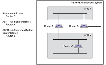
OSPFv3 areas are assigned a number between 0 and 4,294,967,295. Area numbers are often expressed in dotted decimal notation, similar to IP addresses.
Each AS has a backbone area, designated area 0, that connects to all other areas. The backbone receives routing information from all areas and distributes it to the other areas as required.
Neighbors form adjacencies to exchange LSDB information. A neighbor group uses hello packets to elect a Designated Router (DR) and Backup Designated Router (BDR). The DR and BDR become adjacent to all other neighbors, including each other. Only adjacent neighbors share database information.
OSPFv3 Neighbors illustrates OSPFv3 neighbors.
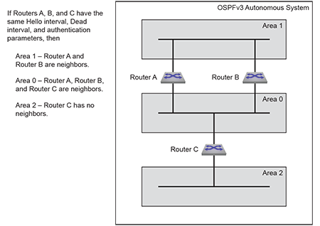
The DR is the central contact for database exchanges. Switches send database information to their DR, which relays the information to the other neighbors. All routers in an area maintain identical LSDBs. Switches also send database information to their BDR, which stores this data without distributing it. If the DR fails, the BDR distributes LSDB information to its neighbors.
OSPFv3 routers distribute LSAs by sending them on all of their active interfaces. The router does not send hello packets from passive interfaces, preventing adjacencies. The router does not process any OSPFv2 packets received on a passive interface.
When an LSA changes a router's LSDB, it sends the changes to the BDR and DR for distribution to the other neighbors. Routing information is updated only when the topology changes.
Routing devices use Dijkstra's algorithm to calculate the shortest path to all known destinations based on cumulative route cost. The cost of an interface indicates the transmission overhead and is usually inversely proportional to its bandwidth.
The OSPFv3 protocol relies on the IPsec Authentication Header (AH) and Encapsulating Security Payload (ESP) header to provide data integrity, authentication, and confidentiality. Transport mode provides IPsec to OSPFv3 packets.
The IPsec SA has a Security Policy Index (SPI), HMAC algorithm, and a secret key as parameters. These parameters are used to compute Integrity Check Value (ICV), that is used to authenticate peers. When authentication is enabled, all corresponding peers must use same SA parameters to clear OSPFv3 ICV verification. SA can be configured at both area and interface levels.
While sending OSPFv3 packets, the system inserts the HMAC-MD5 or SHA algorithm hash in the IPsec header and sends the packet over the wire for peer authentication.
While receiving OSPFv3 packets, the system verifies the computed hash with the one in the IPsec header and discards OSPFv3 packets if it fails.
ESP provides confidentiality to OSPFv3 packets. When confidentiality is enabled, ESP encrypts the sent data and decrypts the received data. OSPFv3 packets that are not encapsulated with a security payload are discarded.
OSPFv3 encryption uses the Triple Data Encryption Standard (3DES) and Advanced Encryption Standard (AES) algorithms. 3DES uses a 192 bit key, whereas the AES key length varies by 128, 192, and 256 bits.
BFD sessions are only established for OSPFv3 adjacencies that are in the FULL state. In a LAN environment, this results in BFD sessions not being established for OSPFv3 adjacencies with DR Other neighbors.
This feature provides configuration that enables the establishment of BFD sessions for OSPFv3 adjacencies that are in any state. This results in the BFD sessions being established for OSPFv3 adjacencies with DR Other neighbors.
The OSPFv3 dn-bit-ignore command enables or disables the inclusion of LSAs with a Down (DN) bit set in SPF calculations. The DN Bit provides a loop prevention mechanism when configuring OSPF as a CE - PE IGP protocol.
The IEEE RFC RFC6565 explains the DN-bit usage in OSPFv3. OSPFv3 honors the DN-bit in type-3, type-5, or type-7 LSAs in non-default VRFs. SPF calculations do not include the LSAs and subsequently do not install them in the routing table. Using the dn-bit-ignore command changes this behavior. Arista Networks recommends understanding the entire topology before configuring the dn-bit-ignore command, as it can lead to forwarding loops on the network.
OSPFv3 configuration commands apply to the specified OSPFv3 instance. The switch must be in router-OSPFv3 configuration mode to execute OSPFv3 configuration commands. The ipv6 router ospf command places the switch in router-OSPFv3 configuration mode, creating an OSPFv3 instance if OSPFv3 was not previously instantiated on the switch. If no VRF is specified, the OSPFv3 instance is in the default VRF. To instantiate or configure OSPFv3 on a non-default VRF, specify that VRF when using the ipv6 router ospf command.
The process ID identifies the OSPFv3 instance and is local to the router. Neighbor OSPFv3 routers can have different process IDs. OSPFv3 instances configured in different VRFs on the switch must have different process IDs.
The switch supports one OSPFv3 instance for each VRF. When an OSPFv3 instance already exists, the ipv6 router ospf command must specify its process ID (and VRF, if not configured in the default VRF). Attempts to define additional instances in the same VRF will generate errors. The show ipv6 ospf command displays information about OSPFv3 instances, including their process IDs.
Example
switch(config)# ipv6 router ospf 9
switch(config-router-ospf3)# show active
ipv6 router ospf 9
switch(config-router-ospf3)#The router ID is a 32-bit number assigned to a router running OSPFv3. This number uniquely labels the router within an Autonomous System. Status commands identify the switch through the router ID. When configuring OSPFv3 instances in multiple VRFs, each should have a different router ID.
The router-id (OSPFv3) command configures the router ID for an OSPFv3 instance.
Example
switch(config-router-ospf3)# router-id 15.1.1.1
switch(config-router-ospf3)# show active
ipv6 router ospf 9
router-id 15.1.1.1
switch(config-router-ospf3)#These router-OSPFv3 configuration mode commands control the OSPFv3 instance's behavior.
The log-adjacency-changes (OSPFv3) command configures the switch to log OSPFv3 link-state changes and transitions of OSPFv3 neighbors into the up or down state.
switch(config-router-ospf3)# log-adjacency-changes
switch(config-router-ospf3)#switch(config-router-ospf3)# log-adjacency-changes detail
switch(config-router-ospf3)#The distance ospf intra-area (OSPFv3) command configures the administrative distance for routes contained in a single OSPFv3 area. Administrative distances compare dynamic routes configured by different protocols. The default administrative distance for intra-area routes is 10.
Example
switch(config-router-ospf3)# distance ospf intra-area 90
switch(config-router-ospf3)# show active
ipv6 router ospf 9
distance ospf intra-area 90
switch(config-router-ospf3)#The passive-interface (OSPFv3) command prevents the transmission of hello packets on the specified interface. Passive interfaces drop all adjacencies and do not form new adjacencies. Although passive interfaces do not send or receive LSAs, others may generate LSAs for the network segment. The router does not send OSPFv3 packets from a passive interface or process OSPFv3 packets received on a passive interface. The router advertises the passive interface in the router LSA.
The no passive-interface command re-enables OSPFv3 processing on the specified interface.
switch(config-router-ospf3)# passive-interface vlan 200
switch(config-router-ospf3)# show active
ipv6 router ospf 9
passive-interface Vlan200
switch(config-router-ospf3)#switch(config-router-ospf3)# no passive-interface vlan 200
switch(config-router-ospf3)# show active
ipv6 router ospf 9
switch(config-router-ospf3)#Redistributing connected routes causes the OSPFv3 instance to advertise all connected routes on the switch as external OSPFv3 routes. Connected routes are routes established when enabling IPv6 on an interface.
Example
switch(config-router-ospf3)# redistribute connected
switch(config-router-ospf3)# show active
ipv6 router ospf 9
redistribute connected
switch(config-router-ospf3)#Redistributing static routes causes the OSPFv3 instance to advertise all static routes on the switch as external OSPFv3 routes. The switch does not support redistributing individual static routes.
Example
switch(config-router-ospf3)# redistribute static
switch(config-router-ospf3)# show active
ipv6 router ospf 9
redistribute static
switch(config-router-ospf3)#Area commands configure OSPFv3 areas. The switch must be in router-OSPFv3 configuration mode to run area commands, as described in Entering OSPFv3 Configuration Mode.
Areas are assigned a 32-bit number expressed in decimal or dotted-decimal notation. When an OSPFv3 instance configuration contains multiple areas, the switch only configures areas associated with its interfaces.
The default area type is normal.
Example
switch(config)# ipv6 router ospf 9
switch(config-router-ospf3)# area 200 nssa
switch(config-router-ospf3)# area 300 stub
switch(config-router-ospf3)# show active
ipv6 router ospf 9
area 0.0.0.200
area 0.0.1.44 stub
switch(config-router-ospf3)#These router-OSPFv3 configuration mode commands define OSPFv3 behavior in a specified area.
The area default-cost (OSPFv3) command specifies the cost of the default summary route that ABRs send into a stub area or NSSA. Summary routes, also called inter-area routes, originate in areas different than their destination. When the area default-cost command is not configured for an area, the default-cost of that area is set to 10.
Example
switch(config-router-ospf3)# area 450 default-cost 25
switch(config-router-ospf3)# show active
ipv6 router ospf 9
area 0.0.1.194 default-cost 25The area stub (OSPFv3) command configures the area type of an OSPFv3 area. All routers in an AS must specify the same area type for identically numbered areas.
Stub areas are areas in which external routes are not advertised. To reach these external routes, the stub area uses a default summary route (::/0). Networks without external routes do not require stub areas.
Areas are normal by default; area type configuration is required only for stub NSSA areas. Area 0 is always a normal area and cannot be configured through this command.
switch(config)# ipv6 router ospf 3
switch(config-router-ospf3)# area 45 stub
switch(config-router-ospf3)#switch(config-router-ospf3)# area 10.92.148.17 stub
switch(config-router-ospf3)#The area range (OSPFv3) command is used by OSPFv3 Area Border Routers (ABRs) to consolidate or summarize routes, configure a cost setting for those routes, and suppress summary route advertisements.
By default, an ABR creates a summary LSA for each route in an area and advertises that LSA to adjacent areas. The area range (OSPFv3) command aggregates routing information on area boundaries, allowing the ABR to use one summary LSA to advertise multiple routes.
switch(config)# ipv6 router ospf 1
switch(config-router-ospf3)# area 1 range 2001:0DB8:0:1::/64
switch(config-router-ospf3)#switch(config)# ipv6 router ospf 1
switch(config-router-ospf3)# area 1 range 2001:0DB8:0:1::/64 not-advertise
switch(config-router-ospf3)#OSPFv3 interface configuration commands enable OSPFv3 on an interface, assign the interface to an area, and specify transmission parameters for routed ports and SVIs that handle OSPFv3 packets.
The ipv6 ospf area command enables OSPFv3 on the configuration mode interface and associates the specified area to the interface. Each routed interface can be associated with one OSPFv3 area; subsequent ipv6 ospf area commands that designate a different area on an interface replace any existing command for the interface.
Example
switch(config)# interface vlan 200
switch(config-if-Vl200)# ipv6 ospf 9 area 0
switch(config-if-Vl200)# show active
interface Vlan200
ipv6 ospf 9 area 0.0.0.0
switch(config-if-Vl200)#Interval configuration commands determine the OSPFv3 packet transmission characteristics for a specified VLAN interface. Interval configuration commands are entered in vlan-interface configuration mode.
The hello interval specifies the period between consecutive hello packet transmissions from an interface. Each OSPFv3 neighbor should specify the same hello interval, which should not be longer than any neighbor's dead interval.
The ospfv3 hello-interval command configures the hello interval for the configuration mode interface. The default is 10 seconds.
Example
switch(config)# interface vlan 200
switch(config-if-Vl200)# ospfv3 hello-interval 45
switch(config-if-Vl200)# show active
interface Vlan200
ospfv3 hello-interval 45
switch(config-if-Vl200)#The dead interval specifies the period that an interface waits for an OSPFv3 packet from a neighbor before it disables the adjacency under the assumption that the neighbor is down. Configure identical dead intervals on all OSPFv3 neighbors. They must be longer than the hello interval of any neighbor.
The ospfv3 dead-interval command configures the dead interval for the configuration mode interface. The default is 40 seconds.
Example
switch(config)# interface vlan 200
switch(config-if-Vl200)# ospfv3 dead-interval 75
switch(config-if-Vl200)# show active
interface Vlan200
ospfv3 dead-interval 75
switch(config-if-Vl200)#Routers that send OSPFv3 advertisements to an adjacent router expect to receive an acknowledgment from that neighbor. If they do not receive an acknowledgment, they will retransmit the advertisement. The retransmission interval specifies the period between retransmissions.
The ospfv3 ipv6 retransmit-interval command configures the LSA retransmission interval for the configuration mode interface. The default retransmission interval is 5 seconds.
Example
switch(config)# interface vlan 200
switch(config-if-Vl200)# ospfv3 ipv6 retransmit-interval 25
switch(config-if-Vl200)# show active
interface Vlan200
ospfv3 ipv6 retransmit-interval 25
switch(config-if-Vl200)#The transmission delay is an estimate of the time that an interface requires to transmit a link-state update packet. OSPFv3 adds this delay to the age of outbound packets to more accurately reflect the age of the LSA when received by a neighbor.
The ospfv3 transmit-delay command configures the transmission delay for the configuration mode interface. The default transmission delay is one second.
Example
switch(config)# interface vlan 200
switch(config-if-Vl200)# ospfv3 transmit-delay 10
switch(config-if-Vl200)# show active
interface Vlan200
ospfv3 transmit-delay 10
switch(config-if-Vl200)#The OSPFv3 interface cost reflects the overhead of sending packets across the interface. The cost is typically assigned to be inversely proportional to the interface's bandwidth. The ospfv3 cost command configures the OSPFv3 cost for the configuration mode interface. The default cost is 10.
Example
switch(config)# interface vlan 200
switch(config-if-Vl200)# ospfv3 cost 50
switch(config-if-Vl200)# show active
interface Vlan200
ospfv3 cost 50
switch(config-if-Vl200)#Router priority determines preference during Designated Router (DR) and Backup Designated Router (BDR) elections. Routers with higher priority numbers have preference over other routers. Routers with a priority of 0 cannot be elected as a DR or BDR.
The ospfv3 priority command configures router priority for the configuration mode interface. The default priority is 1.
Example
switch(config)# interface vlan 200
switch(config-if-Vl200)# ospfv3 priority 128
switch(config-if-Vl200)# show active
interface Vlan200
ospfv3 priority 128
switch(config-if-Vl200)#OSPFv3 requires enabling IPv6 unicast routing on the switch. When IP routing is not enabled, entering OSPFv3 configuration mode generates a message.
switch(config)# ipv6 router ospf 9
! IPv6 routing not enabled
switch(config-router-ospf3)#switch(config)# ipv6 unicast-routingThe shutdown (OSPFv3) disables OSPFv3 operations on the switch without disrupting the OSPFv3 configuration. To disable OSPFv3 on an interface, remove the ipv6 ospf area statement for the corresponding interface.
The no shutdown command resumes OSPFv3 activity.
switch(config)# ipv6 router ospf 9
switch(config-router-ospf3)# shutdown
switch(config-router-ospf3)# show active
ipv6 router ospf 9
shutdown
switch(config-router-ospf3)#switch(config-router-ospf3)# no shutdown
switch(config-router-ospf3)# show active
ipv6 router ospf 9
switch(config-router-ospf3)#You can configure OSPFv3 security for either an area, an interface, or both, using either an Authentication Header (AH) or an Encapsulating Security Payload (ESP).
When configuring OSPFv3 security on an area, the configured settings apply to all interfaces in that area. Interface-specific configuration overrides configuration on the area to which the interface belongs.
Configuring OSPFv3 Authentication for Areas
The area authentication ipsec spi command configures OSPFv3 authentication on an area.
Example
This command configures OSPFv3 authentication on an area with MD5 hash algorithm.
switch(config)# ipv6 router ospf 9
switch(config-router-ospf3)# area 0.0.0.0 authentication ipsec spi 34 md5 0 8FD6158BFE81ADD961241D8E4169D411
switch(config-router-ospf3)# show active
ipv6 router ospf 9
area 0.0.0.0 authentication ipsec spi 34 md5 7 $1$cNpcrQl1czqdvKAzKLtYVr6I7+R3niuWouDKKYCFNs4/XOWG/Iap5Q==
switch(config-router-ospf3)#Configuring OSPFv3 Authentication for Interfaces
The ospfv3 authentication ipsec spi command configures OSPFv3 authentication on an interface.
Example
This command configures OSPFv3 authentication on an interface with MD5 hash algorithm.
switch(config-if-Et9)# ospfv3 authentication ipsec spi 3456 md5 0 8FD6158BFE81ADD961241D8E4169D411
switch(config-if-Et9)# show active
interface Ethernet9
no switchport
ospfv3 authentication ipsec spi 3456 md5 7 $1$xtmcMSPzEn+Njp8Lb4qryVVOjKcjsrYuv6dx1O+nSwKQdaiRt2RPTQ==
switch(config-if-Et9)#Configuring OSPFv3 Encryption for Areas
The area encryption ipsec spi command configures OSPFv3 security on an area.
Example
This command configures OSPFv3 security on an area with 3DES-CBC encryption and MD5 hash algorithm.
switch(config)# ipv6 router ospf 9
switch(config-router-ospf3)# area 0.0.0.0 encryption ipsec spi 5678 esp 3des-cbc md5 passphrase 0 8FD6158BFE81ADD961241D8E4169D411
switch(config-router-ospf3)# show active
ipv6 router ospf 9
area 0.0.0.0 encryption ipsec spi 5678 esp 3des-cbc md5 passphrase 7
$1$cNpcrQl1czqdvKAzKLtYVr6I7+R3niuWouDKKYCFNs4/XOWG/Iap5Q==
switch (config-router-ospf3)#Configuring OSPFv3 Encryption for Interfaces
The ospfv3 encryption ipsec spi command configures OSPFv3 security on an interface.
Example
This command configures OSPFv3 security on an interface with 3DES-CBC encryption and SHA1 algorithm.
switch(config)# interface ethernet 9
switch(config-if-Et9)# ospfv3 encryption ipsec spi 345 esp 3des-cbc sha1 passphrase 0 2fd4e1c67a2d28fced849ee1bb76e7391b93eb12
switch(config-if-Et9)# show active
interface Ethernet9
no switchport
ospfv3 encryption ipsec spi 345 esp 3des-cbc sha1 passphrase 7
$1$VmUkWk6IL2S343bR3BbH0RhgvxHhwBpfvB4VXKNOOQF7HJBp5VvXTfBaVYbgCkWU
switch(config-if-Et9)#You can configure flood pacing for global OSPFv3 instances and address families. The timers pacing flood command configures OSPFv3 flood pacing.
switch(config)# ipv6 router ospf 9
switch(config-router-ospf3)# timers pacing flood 50
switch(config-router-ospf3)# show ipv6 ospf
Routing Process "ospfv3 9" with ID 13.13.13.13 and Instance 0 VRF default
FIPS mode disabled
It is not an autonomous system boundary router and is not an area border router
Minimum LSA arrival interval 1000 msecs
Initial LSA throttle delay 1000 msecs
Minimum hold time for LSA throttle 5000 msecs
Maximum wait time for LSA throttle 5000 msecs
Interface flood pacing timer 50 msecs
It has 0 fully adjacent neighbors
Number of areas in this router is 1. 1 normal, 0 stub, 0 nssa
Number of LSAs 1
Initial SPF schedule delay 0 msecs
Minimum hold time between two consecutive SPFs 5000 msecs
Current hold time between two consecutive SPFs 5000 msecs
Maximum wait time between two consecutive SPFs 5000 msecs
SPF algorithm last executed 21d19h ago
No scheduled SPF
Adjacency exchange-start threshold is 20
Maximum number of next-hops supported in ECMP is 32
Number of backbone neighbors is 0
Graceful-restart is not configured
Graceful-restart-helper mode is enabled
Area 0.0.0.0
Number of interface in this area is 0
It is a normal area
SPF algorithm executed 2 timesswitch(config)# router ospfv3
switch(config-router-ospfv3)# address-family ipv4
switch(config-router-ospfv3-af)# timers pacing flood 50
switch(config-router-ospfv3-af)# show ospfv3
OSPFv3 address-family ipv4
Routing Process "ospfv3" with ID 11.1.11.1 and Instance 64 VRF default
FIPS mode disabled
It is not an autonomous system boundary router and is not an area border router
Minimum LSA arrival interval 1000 msecs
Initial LSA throttle delay 1000 msecs
Minimum hold time for LSA throttle 5000 msecs
Maximum wait time for LSA throttle 5000 msecs
Interface flood pacing timer 50 msecs
It has 0 fully adjacent neighbors
Number of areas in this router is 1. 1 normal, 0 stub, 0 nssa
Number of LSAs 1
Initial SPF schedule delay 0 msecs
Minimum hold time between two consecutive SPFs 5000 msecs
Current hold time between two consecutive SPFs 5000 msecs
Maximum wait time between two consecutive SPFs 5000 msecs
SPF algorithm last executed 00:01:05 ago
No scheduled SPF
Adjacency exchange-start threshold is 20
Maximum number of next-hops supported in ECMP is 32
Number of backbone neighbors is 0
Graceful-restart is not configured
Graceful-restart-helper mode is enabled
Area 0.0.0.0
Number of interface in this area is 0
It is a normal area
SPF algorithm executed 2 timesUse the command dn-bit-ignore to include type-3/5/7 LSAs to set the DN-bit in the SPF calculation.
The commands dn-bit-ignore or default dn-bit-ignore revert the behavior back to default. Use this command in the ipv6 router ospf vrf configuration mode and the router ospfv3 vrf configuration mode. The default VRF does not support this command.
switch(config)# router ospfv3 vrf red
switch(config-router-ospfv3-vrf-red)# dn-bit-ignoreswitch(config)# ipv6 router ospf 1 vrf red
switch(config-router-ospfv3-vrf-red)# dn-bit-ignoreThis section describes OSPFv3 show commands that display OSPFv3 status. General switch methods that provide OSPFv3 information include pinging routes, viewing route status (show ip route command), and viewing the configuration (show running-config command).
The show ipv6 ospf command displays general OSPFv3 configuration information, operational statistics, and status for the OSPFv3 instance, followed by a brief description of the areas configured on the switch.
Example
switch(config-router-ospf3)# show ipv6 ospf
Routing Process "ospfv3 1" with ID 1.1.1.1 and Instance 0 VRF default
It is not an autonomous system boundary router and is not an area border router
Minimum LSA arrival interval 1000 msecs
Initial LSA throttle delay 1000 msecs
Minimum hold time for LSA throttle 5000 msecs
Maximum wait time for LSA throttle 5000 msecs
Interface flood pacing timer 50 msecs
It has 0 fully adjacent neighbors
...
Graceful-restart is not configured
Graceful-restart-helper mode is enabledThe show ipv6 ospf interface command displays OSPFv3 information for switch interfaces configured for OSPFv3. Different command options allow the display of all interfaces or a specified interface. You can configure the command to display complete information or a summary.
Example
switch# show ipv6 ospf interface
Ethernet17 is up
Interface Address fe80::48c:73ff:fe00:1319%Ethernet12, Area 0.0.0.0
Network Type Broadcast, Cost 10
Transmit Delay is 1 sec, State Backup DR, Priority 1
Designated Router is 10.37.0.37
Backup Designated Router is 10.37.0.23
Timer intervals configured, Hello 10, Dead 40, Retransmit 5
Neighbor Count is 1
Vlan31 is up
Interface Address fe80::48c:73ff:fe00:1319%Vlan31, Area 0.0.0.0
Network Type Broadcast, Cost 10
Transmit Delay is 1 sec, State Backup DR, Priority 1
Designated Router is 10.37.0.22
Backup Designated Router is 10.37.0.23
Timer intervals configured, Hello 10, Dead 40, Retransmit 5
Neighbor Count is 1
Vlan32 is up
Interface Address fe80::48c:73ff:fe00:1319%Vlan32, Area 0.0.0.0
Network Type Broadcast, Cost 10
Transmit Delay is 1 sec, State DR Other, Priority 1
Designated Router is 10.37.0.11
Backup Designated Router is 10.37.0.22
Timer intervals configured, Hello 10, Dead 40, Retransmit 5
Neighbor Count is 2
switch#The show ipv6 ospf database <link state list> command displays the LSAs in the LSDB for the specified area. If no area is listed, the command displays the database's contents for each area on the switch. The database command provides options to display subsets of the LSDB database, a summary of database contents, and the link states that comprise the database.
Example
switch# show ipv6 ospf database
Routing Process "ospf 9":
AS Scope LSDB
Type Link ID ADV Router Age Seq# Checksum
AEX 0.0.0.5 10.37.0.37 15 0x80000005 0x00be82
AEX 0.0.0.9 10.37.0.22 1747 0x8000002b 0x00df56
AEX 0.0.0.3 10.37.0.46 599 0x8000002d 0x00651d
Area 0.0.0.0 LSDB
Type Link ID ADV Router Age Seq# Checksum
RTR 0.0.0.0 10.37.0.32 234 0x80000031 0x00585a
NTW 0.0.0.26 10.37.0.32 271 0x80000005 0x005609
NAP 0.0.0.26 10.37.0.32 274 0x80000005 0x00964c
Interface vlan3911 LSDB
Type Link ID ADV Router Age Seq# Checksum
LNK 0.0.0.38 10.37.0.22 267 0x80000005 0x00a45a
LNK 0.0.0.23 10.37.0.23 270 0x8000002c 0x005b7e
Interface vlan3902 LSDB
Type Link ID ADV Router Age Seq# Checksum
LNK 0.0.0.17 10.37.0.11 1535 0x8000002b 0x007120
LNK 0.0.0.37 10.37.0.22 7 0x8000002b 0x00ce23
LNK 0.0.0.22 10.37.0.23 250 0x8000002d 0x00c350
switch#The show ipv6 ospf neighbor command displays information about the routers that are neighbors to the switch. Command options allow the display of summary or detailed information about the neighbors to all areas and interfaces on the switch. The command also allows for the display of neighbors to individual interfaces or areas. The adjacency-changes option displays the interface's adjacency changes.
Example
switch# show ipv6 ospf neighbor
Routing Process "ospf 9":
Neighbor 10.37.0.37 priority is 1, state is Full
In area 0.0.0.0 interface et12
DR is 10.37.0.37 BDR is 10.37.0.23
Options is 0
Dead timer is due in 37 seconds
Neighbor 10.37.0.22 priority is 1, state is Full
In area 0.0.0.0 interface vlan3911
DR is 10.37.0.22 BDR is 10.37.0.23
Options is 0
Dead timer is due in 31 seconds
Neighbor 10.37.0.22 priority is 1, state is Full
In area 0.0.0.0 interface vlan3902
DR is 10.37.0.11 BDR is 10.37.0.22
Options is 0
Dead timer is due in 31 seconds
Neighbor 10.37.0.22 priority is 1, state is Full
In area 0.0.0.0 interface vlan3908
DR is 10.37.0.22 BDR is 10.37.0.21
Options is 0
Dead timer is due in 39 seconds
switch#The show ipv6 routes command provides an OSPFv3 option.
Example
switch# show ipv6 route ospf
IPv6 Routing Table - 43 entries
Codes: C - connected, S - static, K - kernel, O - OSPF, B - BGP, R - RIP, A -
Aggregate
O fd7a:3279:81a4:1112::/64 [150/11]
via fe80::21c:41ff:fe00:d120, Ethernet12
O fd7a:3279:81a4:1114::/64 [150/11]
via fe80::21c:41ff:fe00:d120, Ethernet12
O fd7a:3279:81a4:1124::/64 [10/20]
via fe80::21c:41ff:fe01:5fe1, Vlan3901
via fe80::21c:41ff:fe01:5fe1, Vlan3902
via fe80::21c:41ff:fe01:5fe1, Vlan3908
O fd7a:3279:81a4:1a00::25/128 [150/11]
via fe80::21c:41ff:fe00:d120, Ethernet12
O fd7a:3279:81a4:1a00::28/128 [150/11]
via fd7a:3279:81a4:fe40::5, Vlan3908The show running-config command verifies whether the dn-bit-ignore command is configured.
This section describes the commands required to configure three OSPFv3 topologies.
The AS in Example 1 contains two areas that are connected through two routers. The backbone area also contains an internal router that connects two links.
OSPFv3 Example 1 displays the Example 1 topology. Two ABRs, Router A and Router B, connect Area 0 and Area 1 . Router C is an internal router connecting two links in Area 0. Area 0 is normal; area 1 is stub.
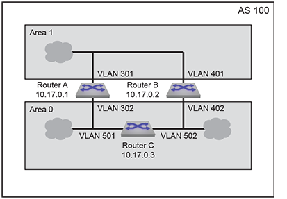
Area 0 contains two links to an internal router.
This code configures the OSPFv3 instances on the three switches.
The AS in Example 2 contains three areas. Area 0 connects to the other areas through different routers and contains an internal router connecting two links. Area 0 is normal; the other areas are stub areas.
OSPFv3 Example 2 displays the Example 2 topology. One ABR (Router B) connects area 0 and area 1; another ABR (Router C) connects area 0 and area 2. Router A is an internal router connecting two links in area 0.
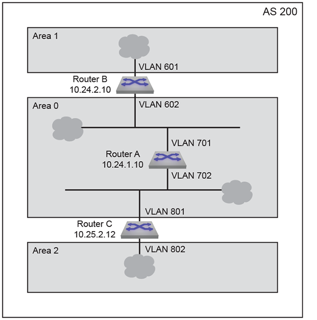
The AS in Example 3 contains two areas that connect through one ABR. Each area also contains an ASBR that connects static routes to the AS.
OSPFv3 Example 3 displays the Example 3 topology. One ABR connects area 0 and area 1. Router C is an ABR connecting the areas. Router A is an internal router connecting two links in area 1. Router D and Router E are internal routers connecting links in area 0. Router B and Router F are ASBRs that connect static routes outside the AS to area 1 and area 0, respectively.
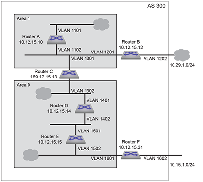
The adjacency exchange-start threshold command sets the exchange-start options for an OSPF instance.
The no adjacency exchange-start threshold and default adjacency exchange-start threshold command resets the default by removing the corresponding adjacency exchange-start threshold command from the running-config.
Command Mode
Router-OSPFv3 Configuration
Command Syntax
adjacency exchange-start threshold peers
no adjacency exchange-start threshold
default adjacency exchange-start threshold
Parameter
peers Value ranges from 1 - 4294967295. Default value is 10.
Example
switch(config)# ipv6 router ospf 3
switch(config-router-ospf3)# adjacency exchange-start threshold 156923
switch(config-router-ospf3)#The area authentication ipsec spi command configures OSPFv3 authentication on an area.
The default area authentication and no area authentication commands delete the OSPFv3 authentication on an area.
Command Mode
Router-OSPFv3 Configuration
Command Syntax
area area_id authentication ipsec spi spi_value {md5|sha1} passphrase {0 unencrypted_key | 7 hidden_key | LINE}
no area area_id authentication ipsec spi spi_value {md5| sha1} passphrase {0 unencrypted_key | 7 hidden_key | LINE}
default area area_id authentication ipsec spi spi_value {md5| sha1} passphrase {0 unencrypted_key | 7 hidden_key | LINE}
Guidelines
Passphrase and key value are exclusive. MD5 and SHA1 keys are derived from the configured passphrase.
Restriction
On the same area, EOS allows security configuration with either AH or ESP but not both. We can have one area configured with AH and another with ESP.
switch(config)# ipv6 router ospf 9
switch(config-router-ospf3)# area 0.0.0.0 authentication ipsec spi 34 md5 0 8FD6158BFE81ADD961241D8E4169D411
switch(config-router-ospf3)# show active
ipv6 router ospf 9
area 0.0.0.0 authentication ipsec spi 34 md5 7 $1$cNpcrQl1czqdvKAzKLtYVr6I7+R3niuWouDKKYCFNs4/XOWG/Iap5Q==
switch(config-router-ospf3)#switch(config)# ipv6 router ospf 9
switch(config-router-ospf3)# area 0.0.0.0 authentication ipsec spi 5789 sha1 passphrase 7 $1$Ab754G0OHbGllIKqlCl7lyUKscUlpFTpvcQxQIhjJm1OUzGJDh4bLWxSdKHvWMo6
switch(config-router-ospf3)# show active
ipv6 router ospf 9
area 0.0.0.0 authentication ipsec spi 5789 sha1 passphrase 7
Ab754G0OHbGllIKqlCl7lyUKscUlpFTpvcQxQIhjJm1OUzGJDh4bLWxSdKHvWMo6
switch(config-router-ospf3)#switch(config)# ipv6 router ospf 9
switch(config-router-ospf3)# show active
ipv6 router ospf 9
area 1.1.1.1 authentication ipsec spi 2437 md5 7 cNpcrQl1czqdvKAzKLtYVr6I7+R3niuWouDKKYCFNs4/XOWG/Iap5Q==
area 0.0.0.0 authentication ipsec spi 5789 sha1 passphrase 7
Ab754G0OHbGllIKqlCl7lyUKscUlpFTpvcQxQIhjJm1OUzGJDh4bLWxSdKHvWMo6
switch(config-router-ospf3)#no area 0.0.0.0 authentication
switch(config-router-ospf3)#show active
ipv6 router ospf 9
area 1.1.1.1 authentication ipsec spi 2437 md5 7 cNpcrQl1czqdvKAzKLtYVr6I7+R3niuWouDKKYCFNs4/XOWG/Iap5Q==
switch(config-router-ospf3)#The area default-cost command sets the cost for the default summary routes sent into an area. When the area default-cost command is not configured for an area, the default-cost of that area is set to 10.
The no area default-cost and default area default-cost command resets the default-cost value of the specified area to 10 by removing the corresponding area default-cost command from running-config. The no area (OSPFv3) command removes all area commands for the specified area from running-config, including the area default-cost command.
Command Mode
Router-OSPFv3 Configuration
Command Syntax
area area_id default-cost def_cost
no area area_id default-cost
default area area_id default-cost
Example
switch(config)# ipv6 router ospf 9
switch(config-router-ospf3)# area 100 default 15
switch(config-router-ospf3)# show active
ipv6 router ospf 9
area 0.0.0.100 default-cost 15
switch(config-router-ospf3)#The area encryption ipsec spi command configures OSPFv3 security on an area.
The default area encryption andno area encryptioncommands delete the OSPFv3 security on an area.
Command Mode
Router-OSPFv3 Configuration
Command Syntax
area area_id encryption ipsec spi spi_value esp{3des-cbc| aes-128-cbc | aes-192-cbc | aes-256-cbc}{ 0 unencrypted_key | 7 encrypted_key}{ md5| sha1} { 0 unencrypted_key | 7 encrypted_key | KEY}
area area_id encryption ipsec spi spi_value esp null{md5 | sha1} { 0 unencrypted_key | 7 encrypted_key | KEY}
area area_id encryption ipsec spi spi_value esp{3des-cbc | aes-128-cbc | aes-192-cbc | aes-256-cbc | null} {md5 | sha1} { 0 unencrypted_key | 7 encrypted_key | LINE}
no area area_id encryption
default area area_id encryption
Parameters
Passphrase and key values are exclusive. MD5 and SHA1 keys are derived from the configured passphrase.
Restriction
On the same area, EOS allows security configuration with either AH or ESP but not both. We can have one area configured with AH and another with ESP.
switch(config)# ipv6 router ospf 9
switch(config-router-ospf3)# area 0.0.0.0 encryption ipsec spi 5678 esp 3des-cbc md5 passphrase 0
8FD6158BFE81ADD961241D8E4169D411
switch(config-router-ospf3)# show active
ipv6 router ospf 9
area 0.0.0.0 encryption ipsec spi 5678 esp 3des-cbc md5 passphrase 7
$1$cNpcrQl1czqdvKAzKLtYVr6I7+R3niuWouDKKYCFNs4/XOWG/Iap5Q==
switch (config-router-ospf3)#switch(config)# ipv6 router ospf 9
switch(config-router-ospf3)# show active
ipv6 router ospf 9
area 0.0.0.0 encryption ipsec spi 5678 esp 3des-cbc md5 passphrase 7
$1$cNpcrQl1czqdvKAzKLtYVr6I7+R3niuWouDKKYCFNs4/XOWG/Iap5Q==
switch(config-router-ospf3)# no area 0.0.0.0 encryption
switch(config-router-ospf3)# show active
ipv6 router ospf 9
switch(config-router-ospf3)#The area not-so-stubby lsa type-7 convert type-5 command configures the switch to always translate Type-7 Link-State Advertisement (LSAs) to Type-5 LSAs.
The no area not-so-stubby lsa type-7 convert type-5 and no area not-so-stubby lsa type-7 convert type-5 commands allow LSAs to be translated dynamically by removing the no area not-so-stubby lsa type-7 convert type-5 command from the running-config.
Command Mode
Router-OSPFv3 Configuration
Command Syntax
area area_id not-so-stubby lsa type-7 convert type-5
no area area_id not-so-stubby lsa type-7 convert type-5
default area area_id not-so-stubby lsa type-7 convert type-5
Parameters
Example
switch(config)# ipv6 router ospf 3
switch(config-router-ospf3)# area 3 not-so-stubby lsa type-7 convert type-5
switch(config-router-ospf)#The area nssa command configures an OSPFv3 area as a Not-So-Stubby Area (NSSA). All routers in an AS must specify the same area type for identically numbered areas.
NSSA ASBRs advertise external LSAs that are part of the area, but do not advertise external LSAs from other areas.
Areas are normal by default; area type configuration is required only for stub NSSA areas. Area 0 is always a normal area and cannot be configured through this command.
The no area nssa command configures the specified area as a normal area by removing the specified area nssa command from running-config.
Command Mode
Router-OSPFv3 Configuration
Command Syntax
area area_id nssa [TYPE]
no area area_id nssa [TYPE]
default area area_id nssa [TYPE]
Example
switch(config)# ipv6 router ospf 1
switch(config-router-ospf3)# area 3 nssa nssa-only
switch(config-router-ospf3)#The area nssa default-information-originate command sets an area as an NSSA and the generation of a type 7 default LSA is created if a default route exists in the routing table.
The switch supports three area types:
Areas are normal by default; area type configuration is required only for stub NSSA areas. Area 0 is always a normal area and cannot be configured through this command.
The no areaand default area commands remove the specified area from the OSPFv3 instance by deleting all area commands from the running-config for the specified area, including the area default-cost (OSPFv3) command.
The no area stub and default area stub commands configure the specified area as a normal area.
Command Mode
Router-OSPFv3 Configuration
Command Syntax
area area_id nssa default-information-originate [VALUE][TYPE][EXCL]
no area area_id nssa default-information-originate [VALUE][TYPE][EXCL]
default area area_id nssa default-information-originate [VALUE][TYPE][EXCL]
Parameters
switch(config-router-ospf3)# area 3 nssa default-information-originate nssa-only
switch(config-router-ospf3)#switch(config-router-ospf3)# area 3 nssa default-information-originate
switch(config-router-ospf3)#The area range command is used by OSPFv3 area border routers to summarize routes.
The no area range and default area range commands remove the area-range by deleting the corresponding area range command from the running-config.
Command Mode
Router-OSPFv3 Configuration
Command Syntax
area area_id range net_addr [ADVERTISE_SETTING][COST_SETTING]
no area area_id range net_addr [ADVERTISE_SETTING][COST_SETTING]
default area area_id range net_addr [ADVERTISE_SETTING][COST_SETTING]
cost range_cost Value ranges from 1 to 65535.
switch(config)# ipv6 router ospf 1
switch(config-router-ospf3)# area 1 range 2001:0DB8:0:1::/64
switch(config-router-ospf3)#switch(config)# ipv6 router ospf 1
switch(config-ospf6-router)# area 1 range 2001:0DB8:0:1::/64 not-advertise
switch(config-ospf6-router)#The area stub command configures the area type of an OSPFv3 area.
Areas are normal by default.
The no area stub command configures the specified area as a normal area.
Command Mode
Router-OSPFv3 Configuration
Command Syntax
area area_id stub
no area area_id stub
default area area_id stub
Parameters
switch(config)# ipv6 router ospf 3
switch(config-router-ospf3)# area 45 stub
switch(config-router-ospf3)#switch(config-router-ospf3)# area 10.92.148.17 stub
switch(config-router-ospf3)#The clear ospfv3 ipv6 force-spf command starts the SPF algorithm without clearing the OSPF database.
Command Mode
Privileged EXEC
Command Syntax
clear ospfv3 ipv6 force-spf [VRF_INSTANCE]
Parameters
Example
switch(config)# clear ospfv3 ipv6 force-spf
switch(config)#The default-information originate command generates a default external route into an OSPF domain.
The no default-information originate and default default-information originate command removes the configuration from the the running-config.
Command Mode
Router-OSPFv3 Configuration
Command Syntax
default-information originate [DURATION always][VALUE metric 1-65535][TYPE][metric-type 1-2][MAP route-map map_name]
no default-information originate
default default-information originate
Parameters
switch(config)# ipv6 router ospf 1
switch(config-router-ospf3)# default-information originate always
switch(config-router-ospf3)# show active
ipv6 router ospf 1
default-information originate alwaysswitch(config)# ipv6 router ospf 1
switch(config-router-ospf3)# default-information originate metric 100 metric-type 1
switch(config-router-ospf3)# show active
ipv6 router ospf 1
default-information originate metric 100 metric-type 1
switch(config-router-ospf3)#The default-metric command sets default metric value for routes redistributed into the OSPFv3 domain.
The no default-metric and default default-metric commands restores the default metric to its default value of 10 by removing the default-metric command from the running-config.
Command Mode
Router-OSPFv3 Configuration
Command Syntax
default-metric def_metric
no default-metric
default default-metric
Parameter
def_metric Values range from 1 to 65535. Default value is 10.
Example
switch(config)# ipv6 router ospf 9
switch(config-router-ospf3)# default-metric 30
switch(config-router-ospf3)# show active
ipv6 router ospf 9
default-metric 30
switch(config-router-ospf3)#The distance ospf intra-area command sets the administrative distance for routes in a single OSPFv3 area. The default is 110.
The no distance ospf intra-area and default distance ospf intra-area commands remove the distance ospf intra-area command from the running-config, returning the OSPFv3 intra-area distance setting to the default value of 110
Command Mode
Router-OSPFv3 Configuration
Command Syntax
distance ospf intra-area distance
no distance ospf intra-area
default distance ospf intra-area
Parameter
distance Values range from 1 to 255. Default is 110.
Example
switch(config)# ipv6 router ospf 9
switch(config-router-ospf3)# distance ospf intra-area 90
switch(config-router-ospf3)# show active
ipv6 router ospf 9
distance ospf intra-area 90
switch(config-router-ospf3)#The ipv6 ospf area command enables OSPFv3 on the interface and associates the area to the interface.
OSPFv3 areas are configured in by no area (OSPFv3) commands in router-OSPFv3 configuration mode.
The no ipv6 ospf area and default ipv6 ospf area commands disable OSPFv3 on the configuration mode interface by removing the corresponding ipv6 ospf area command from the running-config.
Command Mode
Interface-Ethernet Configuration
Interface-Loopback Configuration
Interface-Port-Channel Configuration
Interface-VLAN Configuration
Command Syntax
ipv6 ospf process_id [area area_id]
no ipv6 ospf process_id [area area_id]
default ipv6 ospf process_id [area area_id]
Example
switch(config)# interface vlan 200
switch(config-if-Vl200)# ipv6 ospf 9 area 0
switch(config-if-Vl200)# show active
interface Vlan200
ipv6 ospf 9 area 0.0.0.0
switch(config-if-Vl200)#The ipv6 router ospf command places the switch in router-OSPFv3 configuration mode and creates and OSPFv3 instance if one does not already exist. Note that each OSPFv3 instance on the switch must have a unique process ID. A router ID for the new instance will be created if one does not already exist.
The show ipv6 ospf command displays the router ID of each OSPFv3 instance configured on the switch.
The no ipv6 router ospf and default ipv6 router ospf commands delete the OSPFv3 instance.
Refer to the Router-OSPFv3 Configuration Mode command for a list of commands available in router-OSPFv3 configuration mode.
Command Mode
Global Configuration
Command Syntax
ipv6 router ospf process_id [VRF_INSTANCE vrf vrf_name]
no ipv6 router ospf process_id [ VRF_INSTANCE vrf vrf_name]
default ipv6 router ospf process_id [ VRF_INSTANCE vrf vrf_name]
switch(config)# ipv6 router ospf 9
switch(config-router-ospf3)# show active
ipv6 router ospf 9
switch(config-router-ospf3)#switch(config)# no ipv6 router ospf 9
switch(config)#The log-adjacency-changes command enables syslog messages to be sent when it detects OSPFv3 link state changes or when it detects that a neighbor has gone up or down. Log message sending is enabled by default.
The default log-adjacency-changes command restores the default state by removing the log-adjacency-changes statement from the running-config.
The default option (sending a message only when a neighbor goes up or down) is active when the running-config does not contain any form of the command. Entering the command in any form replaces the previous command state in the running-config.
The no log-adjacency-changes disables link state change Syslog reporting.
The default log-adjacency-changes command restores the default state by removing the log-adjacency-changes detail or no log-adjacency-changes statement from the running-config.
Command Mode
Router-OSPFv3 Configuration
Command Syntax
log-adjacency-changes [INFO_LEVEL detail]
no log-adjacency-changes
default log-adjacency-changes
Parameters
Example
switch(config)# ipv6 router ospf 9
switch(config-router-ospf3)# log-adjacency-changes
switch(config-router-ospf3)# show active
ipv6 router ospf 9
log-adjacency-changes
switch(config-router-ospf3)#The maximum-paths command sets the maximum number of parallel routes that OSPFv3 supports on the switch.
The no maximum-paths command restores the maximum number of parallel routes that OSPFv3 supports on the switch to the default value of 16 by removing the maximum-paths command from running-config.
Command Mode
Router-OSPFv3 Configuration
Command Syntax
maximum-paths paths
no maximum-paths
default maximum-paths
Parameters
Example
switch(config)# ipv6 router ospf 9
switch(config-router-ospf3)# maximum-paths 12
switch(config-router-ospf3)#The max-metric router-lsa command configures OSPF to include the maximum value in LSA metric fields to keep other network devices from using the switch as a preferred intermediate SPF hop.
The no max-metric router-lsa and default max-metric router-lsa commands disable the advertisement of a maximum metric.
Command Mode
Router-OSPFv3 Configuration
Command Syntax
max-metric router-lsa [EXTERNAL][STUB][STARTUP][SUMMARY]
no max-metric router-lsa [EXTERNAL][STUB][STARTUP][SUMMARY]
default max-metric router-lsa [EXTERNAL][STUB][STARTUP][SUMMARY]
Parameters
wait-for-bgp or an on-start time value is not included in no and default commands.
Example
switch(config-router-ospf3)# max-metric router-lsa on-startup wait-for-bgp
switch(config-router-ospf3)#Area settings can be removed individually; refer to the command description page of the desired command for details.
Command Mode
Router-OSPFv3 Configuration
Command Syntaxno area area_id [TYPE]
default area area_id [TYPE]
Example
switch(config)# ipv6 router ospf 9
switch(config-router-ospf3)# no area 1 stub
switch(config-router-ospf3)#Theospfv3 transmit-delay command configures the transmission delay for OSPFv3 packets.
The no ospfv3 transmit-delay and default ospfv3 transmit-delay commands restore the default transmission delay of 1 second on the configuration mode interface by removing the corresponding ospfv3 transmit-delay command from running-config.
Command Mode
Interface-Ethernet Configuration
Interface-Loopback Configuration
Interface-Port-Channel Configuration
Interface-VLAN Configuration
Command Syntax
ospfv3 transmit-delay trans
no ospfv3 transmit-delay
default ospfv3 transmit-delay
Parameter
trans Value ranges from 1 to 65535; default is 1.
Guideline
Arista devices also support the legacy ipv6 ospf transmit-delay command in certain software releases of the EOS.
Exampleswitch(config)# interface vlan 200
switch(config-if-Vl200)# ospfv3 transmit-delay 10
switch(config-if-Vl200)# show active
interface Vlan200
ospfv3 transmit-delay 10
switch(config-if-Vl200)#The ospfv3 authentication ipsec spi command configures OSPFv3 authentication on an interface.
The default ospfv3 authentication and no ospfv3 authentication commands delete the OSPFv3 authentication on an interface.
Command Mode
Interface-Ethernet Configuration
Command Syntax
ospfv3 authentication ipsec spi spi_value {md5 | sha1}{0 unencrypted_key | 7 hidden_key | KEY}
ospfv3 authentication ipsec spi spi_value {md5 | sha1} passphrase{0 unencrypted_passphrase | 7 hidden_passphrase | LINE}
no ospfv3 authentication
default ospfv3 authentication
Guidelines
Passphrase and key values are exclusive. MD5 and SHA1 keys are derived from the configured passphrase. Arista devices also support the legacy ipv6 ospf authentication ipsec spi command in certain software releases of the EOS.
Restriction
On the same interface, EOS allows security configuration with either AH or ESP but not both. We can have one interface configured with AH and another with ESP.
switch(config)# interface ethernet 9
switch(config-if-Et9)# ospfv3 authentication ipsec spi 3456 md5 0 8FD6158BFE81ADD961241D8E4169D411
switch(config-if-Et9)# show active
interface Ethernet9
no switchport
ospfv3 authentication ipsec spi 3456 md5 7 $1$xtmcMSPzEn+Njp8Lb4qryVVOjKcjsrYuv6dx1O+nSwKQdaiRt2RPTQ==
switch(config-if-Et9)#switch(config)# interface ethernet 9
switch(config-if-Et9)# ospfv3 authentication ipsec spi 987 sha1 7 $1$VmUkWk6IL2S343bR3BbH0RhgvxHhwBpfvB4VXKNOOQF7HJBp5VvXTfBaVYbgCkWU
switch(config-if-Et9)# show active
interface Ethernet9
no switchport
ospfv3 authentication ipsec spi 987 sha1 7
$1$VmUkWk6IL2S343bR3BbH0RhgvxHhwBpfvB4VXKNOOQF7HJBp5VvXTfBaVYbgCkWU
switch(config-if-Et9)#switch(config)# interface ethernet 9
switch(config-if-Et9)# show active
interface Ethernet9
no switchport
ospfv3 authentication ipsec spi 3456 md5 7 $1$xtmcMSPzEn+Njp8Lb4qryVVOjKcjsrYuv6dx1O+nSwKQdaiRt2RPTQ==
switch(config-if-Et9)#no ospfv3 authentication
switch(config-if-Et9)#show active
interface Ethernet9
no switchport
switch(config-if-Et9)#The ospfv3 cost command sets the OSPFv3 cost for the interface. The default OSPFv3 cost is 10.
The no ospfv3 cost and default ospfv3 cost commands restore the default cost of 10 for the configuration mode interface by removing the corresponding ospfv3 cost command from the running-config.
Command Mode
Interface-Ethernet Configuration
Interface-Loopback Configuration
Interface-Port-Channel Configuration
Interface-VLAN Configuration
Command Syntax
ospfv3 cost interface_cost
no ospfv3 cost
default ospfv3 cost
Parameters
interface_cost Value ranges from 1 to 65535; default is 10.
Guideline
Arista devices also support the legacy ipv6 ospf cost command in certain software releases of the EOS.
Example
switch(config)# interface vlan 200
switch(config-if-Vl200)# ospfv3 cost 50
switch(config-if-Vl200)# show active
interface Vlan200
ospfv3 cost 50
switch(config-if-Vl200)#The ospfv3 dead-interval command sets the OSPFv3 dead interval.
The no ospfv3 dead-interval and default ospfv3 dead-interval commands restore the default dead interval of 40 seconds on the configuration mode interface by removing the corresponding ospfv3 dead-interval command from the running-config.
Command Mode
Interface-Ethernet Configuration
Interface-Loopback Configuration
Interface-Port-Channel Configuration
Interface-VLAN Configuration
Command Syntax
ospfv3 dead-interval time
no ospfv3 dead-interval
default ospfv3 dead-interval
Parameter
time Value ranges from 1 to 65535; default is 40.
Guideline
Arista devices also support the legacy ipv6 ospf dead-interval command in certain software releases of the EOS.
Example
switch(config)# interface vlan 200
switch(config-if-Vl200)# ospfv3 dead-interval 75
switch(config-if-Vl200)# show active
interface Vlan200
ospfv3 dead-interval 75
switch(config-if-Vl200)#The ospfv3 encryption ipsec spi command configures OSPFv3 security on an interface.
The default ospf3 encryption and no ospfv3 encryption commands delete the OSPFv3 security on an interface.
Command Mode
Interface-Ethernet Configuration
Command Syntax
ospfv3 encryption ipsec spi spi_value esp {3des-cbc | aes-128-cbc | aes-128-cbc | aes-192-cbc}{0 unencrypted_key | 7 encrypted_key} {md5 | sha1}{0 unencrypted_key | 7 encrypted_key | KEY}
ospfv3 encryption ipsec spi spi_value esp {3des-cbc | aes-128-cbc | aes-128-cbc | aes-192-cbc}{0 unencrypted_key | 7 encrypted_key}{md5 | sha1} passphrase {0 unencrypted_passphrase | 7 encrypted_passphrase | LINE}
ospfv3 encryption ipsec spi spi_value esp null {md5 | sha1}{0 unencrypted_key | 7 encrypted_key | KEY}
ospfv3 encryption ipsec spi spi_value esp {md5 | sha1} passphrase {0 unencrypted_passphrase | 7 encrypted_passphrase | LINE}
default ospfv3 encryption
no ospf3 encryption
Guidelines
Passphrase and key value are exclusive. MD5 and SHA1 keys are derived from the configured passphrase. Arista devices also support the legacy ipv6 ospf encryption ipsec spi command in certain software releases of the EOS.
Restrictions
On the same interface, EOS allows security configuration with either AH or ESP but not both. We can have one interface configured with AH and another with ESP.
switch(config)# interface ethernet 9
switch(config-if-Et9)# ospfv3 encryption ipsec spi 345 esp 3des-cbc sha1 passphrase 0 2fd4e1c67a2d28fced849ee1bb76e7391b93eb12
switch(config-if-Et9)# show active
interface Ethernet9
no switchport
ospfv3 encryption ipsec spi 345 esp 3des-cbc sha1 passphrase 7
$1$VmUkWk6IL2S343bR3BbH0RhgvxHhwBpfvB4VXKNOOQF7HJBp5VvXTfBaVYbgCkWU
switch(config-if-Et9)#switch(config)# interface ethernet 9
switch(config-if-Et9)# ospfv3 encryption ipsec spi 345 esp 3des-cbc md5 passphrase 7 $1$VmUkWk6IL2S343bR3BbH0RhgvxHhwBpfvB4VXKNOOQF7HJBp5VvXTfBaVYbgCkWU
switch(config-if-Et9)# show active
interface Ethernet9
no switchport
ospfv3 encryption ipsec spi 345 esp 3des-cbc md5 passphrase 7
$1$VmUkWk6IL2S343bR3BbH0RhgvxHhwBpfvB4VXKNOOQF7HJBp5VvXTfBaVYbgCkWU
switch(config-if-Et9)#switch(config)# interface ethernet 9
switch(config-if-Et9)# show active
interface Ethernet9
no switchport
ospfv3 encryption ipsec spi 3456 md5 7 $1$xtmcMSPzEn+Njp8Lb4qryVVOjKcjsrYuv6dx1O+nSwKQdaiRt2RPTQ==
switch(config-if-Et9)#no ospfv3 encryption
switch(config-if-Et9)#show active
interface Ethernet9
no switchport
switch(config-if-Et9)#The ospfv3 hello-interval command sets the OSPFv3 hello interval. The hello interval is the period between the transmission of consecutive hello packets.
Each OSPFv3 neighbor should be the same hello interval and should not be longer than any neighbors dead interval.
The no ospfv3 hello-interval and default ospfv3 hello-interval commands restore the default hello interval of 10 seconds on the configuration mode interface by removing the ospfv3 hello-interval command from running-config.
Command Mode
Interface-Ethernet Configuration
Interface-Loopback Configuration
Interface-Port-Channel Configuration
Interface-VLAN Configuration
Command Syntax
ospfv3 hello-interval time
no ospfv3 hello-interval
default ospfv3 hello-interval
Parameter
timeValues range from 1 to 65535; default is 10.
Guideline
Arista devices also support the legacy ipv6 ospf hello-interval command in certain software releases of the EOS.
Example
switch(config)# interface vlan 200
switch(config-if-Vl200)# ospfv3 hello-interval 45
switch(config-if-Vl200)# show active
interface Vlan200
ospfv3 hello-interval 45
switch(config-if-Vl200)#The ospfv3 ipv6 retransmit-interval command configures the link state advertisement retransmission interval.
The no ospfv3 ipv6 retransmit-interval and default ospfv3 ipv6 retransmit-interval commands restore the default retransmission interval of 5 seconds on the configuration mode interface by removing the corresponding ospfv3 ipv6 retransmit-interval command from the running-config.
Command Mode
Interface-Ethernet Configuration
Interface-Loopback Configuration
Interface-Port-Channel Configuration
Interface-VLAN Configuration
Command Syntax
ospfv3 ipv6 retransmit-interval period
no ospfv3 ipv6 retransmit-interval
default ospfv3 ipv6 retransmit-interval
Parameter
period Value ranges from 1 to 65535; default is 5.
Example
switch(config)# interface vlan 200
switch(config-if-Vl200)# ospfv3 ipv6 retransmit-interval 25
switch(config-if-Vl200)# show active
interface Vlan200
ospfv3 ipv6 retransmit-interval 25
switch(config-if-Vl200)#The ospfv3 network command sets the configuration mode interface as a point-to-point link. By default, interfaces are set as broadcast links.
The no ospfv3 network and default ospfv3 network commands set the configuration mode interface as a broadcast link by removing the corresponding ospfv3 network command from the running-config.
Command Mode
Interface-Ethernet Configuration
Interface-Loopback Configuration
Interface-Port-Channel Configuration
Interface-VLAN Configuration
Command Syntax
ospfv3 network point-to-point
no ospfv3 network
default ospfv3 network
Guideline
Arista devices also support the legacy ipv6 ospf network command in certain software releases of the EOS.
switch(config)# interface vlan 200
switch(config-if-Vl200)# ospfv3 network point-to-point
switch(config-if-Vl200)# show active
interface Vlan200
ospfv3 network point-to-point
switch(config-if-Vl200)#switch(config)# interface vlan 200
switch(config-if-Vl200)# no ospfv3 network
switch(config-if-Vl200)# show active
interface Vlan200
switch(config-if-Vl200)#The ospfv3 priority command configures the OSPFv3 router priority.
The no ospfv3 priority and default ospfv3 priority commands restore the default priority (1) on the interface by removing the corresponding ospfv3 priority command from the running-config.
Command Mode
Interface-Ethernet Configuration
Interface-Loopback Configuration
Interface-Port-Channel Configuration
Interface-VLAN Configuration
Command Syntax
ospfv3 priority priority_level
no ospfv3 priority
default ospfv3 priority
Parameter
priority_level Settings range from 0 to 255.
Guideline
Arista devices also support the legacy ipv6 ospf prioritycommand in certain software releases of the EOS.
Example
switch(config)# interface vlan 200
switch(config-if-Vl200)# ospfv3 priority 128
switch(config-if-Vl200)# show active
interface Vlan200
ospfv3 priority 128
switch(config-if-Vl200)#The passive-interface command disables OSPF on an interface range. All interfaces are active by default.
The no passive-interface and default passive-interface commands enable OSPFv3 on the specified interface range by removing the corresponding passive-interface statements from the running-config.
Command Mode
Router-OSPFv3 Configuration
Command Syntax
passive-interface INTERFACE_NAME
no passive-interface INTERFACE_NAME
default passive-interface INTERFACE_NAME
Valid e_range, l_range, m_range, p_range v_range, and vx_range formats include number, range, or comma-delimited list of numbers and ranges.
Example
switch(config)# ipv6 router ospf 9
switch(config-router-ospf3)# passive-interface vlan 101-103
switch(config-router-ospf3)# show active
ipv6 router ospf 9
passive-interface Vlan101
passive-interface Vlan102
passive-interface Vlan103
switch(config-router-ospf3)#The redistribute command enables the advertising of all specified routes into the OSPFv3 domain as external routes.
The no redistribute and default redistribute commands remove the corresponding redistribute command from the running-config, disabling route redistribution for the specified route type.
Command Mode
Router-OSPFv3 Configuration
Command Syntax
redistribute ROUTE_TYPE ROUTE_MAP
no redistribute ROUTE_TYPE
default redistribute ROUTE_TYPE
Example
switch(config)# ipv6 router ospf 9
switch(config-router-ospf3)# redistribute static
switch(config-router-ospf3)# show active
ipv6 router ospf 9
redistribute connected
redistribute static
switch(config-router-ospf3)#The router-id command assigns the router ID for an OSPFv3 instance. The switch sets the router ID to the first available alternative in the following list:
The no router-id and default router-id commands remove the router ID command from the running-config.
Command Mode
Router-OSPFv3 Configuration
Command Syntax
router-id identifier
no router-id
default router-id
Parameters
identifier Value ranges from 0.0.0.0 to 255.255.255.255 (dotted decimal notation).
Example
switch(config)# ipv6 router ospf 9
switch(config-router-ospf3)# router-id 10.10.1.4
switch(config-router-ospf3)# show active
ipv6 router ospf 9
router-id 15.10.1.4
switch(config-router-ospf3)#The show ipv6 ospf border-routers command displays the OSPF routing table entries.
Command Mode
EXEC
Command Syntax
show ipv6 ospf border-routers [VRF_INSTANCE vrf vrf_name]
Example
switch# show ipv6 ospf border-routers
Routing Process "ospf 9", VRF default
Router 10.37.0.32 area 0.0.0.0 ASBR
Router 10.37.0.18 area 0.0.0.0 ASBR
Router 10.37.0.22 area 0.0.0.0 ASBR ABR
Router 10.37.0.31 area 0.0.0.0 ASBR ABR
Router 10.37.0.58 area 0.0.0.0 ASBR
Router 10.37.0.37 area 0.0.0.0 ASBR
Router 10.37.0.22 area 0.0.0.2 ASBR ABR
Router 10.37.0.31 area 0.0.0.2 ASBR ABRThe show ipv6 ospf database link command displays link state advertisement details. The switch can return link state data about a single area or for all areas on the switch.
Command Mode
EXEC
Command Syntax
show ipv6 ospf database link if-name [INTF_ID][LS_ID][ROUTER][DATA_LEVEL]
Valid range formats include number, range, or comma-delimited list of numbers and ranges.
Example
switch# show ipv6 ospf database link if-name ethernet 4/1
Codes: AEX - AS External, GRC - Grace,
IAP - Inter Area Prefix, IAR - Inter Area Router,
LNK - Link, NAP - Intra Area Prefix,
NSA - Not So Stubby Area, NTW - Network,
RTR - Router
Routing Process "ospf 1":The show ipv6 ospf database link command displays information of the link state advertisements. The switch can return link state data about a single area or for all areas on the switch.
Command Mode
EXEC
Command Syntax
show ipv6 ospf database link if-type [INTF_TYPE][LS_ID][ROUTER][DATA_LEVEL]
Example
switch# show ipv6 ospf database link if-type broadcast
Codes: AEX - AS External, GRC - Grace,
IAP - Inter Area Prefix, IAR - Inter Area Router,
LNK - Link, NAP - Intra Area Prefix,
NSA - Not So Stubby Area, NTW - Network,
RTR - Router
Routing Process "ospf 1":
Interface et4 LSDB
Type Link ID ADV Router Age Seq# Checksum
LNK 0.0.0.61 10.26.0.49 1378 0x80000027 0x00f8b0
LNK 0.0.0.20 10.26.0.23 1371 0x80000027 0x005423
Interface et7 LSDB
Type Link ID ADV Router Age Seq# Checksum
LNK 0.0.0.61 10.26.0.50 1298 0x80000028 0x005e0d
LNK 0.0.0.38 10.26.0.23 1291 0x80000028 0x00ce8d
Interface vlan3901 LSDB
Type Link ID ADV Router Age Seq# Checksum
LNK 0.0.0.36 10.26.0.22 216 0x800000b0 0x00c2b1
LNK 0.0.0.19 10.26.0.23 231 0x800000b0 0x00cfcaThe show ipv6 ospf database command displays the OSPF link state advertisements that originate on a switch.
Command Mode
EXEC
Command Syntax
show ipv6 ospf database [FILTER][LINKSTATE_ID][ROUTER][DATA_LEVEL]
Example
switch# show ipv6 ospf database 10.26.0.23
Codes: AEX - AS External, GRC - Grace,
IAP - Inter Area Prefix, IAR - Inter Area Router,
LNK - Link, NAP - Intra Area Prefix,
NSA - Not So Stubby Area, NTW - Network,
RTR - Router
Routing Process "ospf 9":
AS Scope LSDB
Type Link ID ADV Router Age Seq# Checksum
AEX 0.0.0.5 10.37.0.37 15 0x80000005 0x00be82
AEX 0.0.0.9 10.37.0.22 1747 0x8000002b 0x00df56
AEX 0.0.0.3 10.37.0.46 599 0x8000002d 0x00651d
Area 0.0.0.0 LSDB
Type Link ID ADV Router Age Seq# Checksum
RTR 0.0.0.0 10.37.0.32 234 0x80000031 0x00585a
NTW 0.0.0.26 10.37.0.32 271 0x80000005 0x005609
NAP 0.0.0.26 10.37.0.32 274 0x80000005 0x00964c
Interface vlan3911 LSDB
Type Link ID ADV Router Age Seq# Checksum
LNK 0.0.0.38 10.37.0.22 267 0x80000005 0x00a45a
LNK 0.0.0.23 10.37.0.23 270 0x8000002c 0x005b7e
Interface vlan3902 LSDB
Type Link ID ADV Router Age Seq# Checksum
LNK 0.0.0.17 10.37.0.11 1535 0x8000002b 0x007120
LNK 0.0.0.37 10.37.0.22 7 0x8000002b 0x00ce23
LNK 0.0.0.22 10.37.0.23 250 0x8000002d 0x00c350The show ipv6 ospf database link command displays details of the specified link state advertisements. The switch can return link state data about a single area or for all areas on the switch.
Command Mode
EXEC
Command Syntax
show ipv6 ospf database link [LINKSTATE_ID][ROUTER][DATA_LEVEL]
Example
switch# show ipv6 ospf database link
Codes: AEX - AS External, GRC - Grace,
IAP - Inter Area Prefix, IAR - Inter Area Router,
LNK - Link, NAP - Intra Area Prefix,
NSA - Not So Stubby Area, NTW - Network,
RTR - Router
Routing Process "ospf 9":The show ipv6 ospf database command displays data from the OSPF database. The switch can return link state data for a single VRF or for all VRFs on the switch.
Command Mode
EXEC
Command Syntax
show ipv6 ospf database [VRF_INSTANCE vrf vrf_name]
Example
switch# show ipv6 ospf database vrf blue
Codes: AEX - AS External, GRC - Grace,
IAP - Inter Area Prefix, IAR - Inter Area Router,
LNK - Link, NAP - Intra Area Prefix,
NSA - Not So Stubby Area, NTW - Network,
RTR - Router
Routing Process "ospf 9", VRF blue
AS Scope LSDBThe show ipv6 ospf database <link-state details> command displays detailed information about the specified link state advertisements. The switch can return link state data about a single area or for all areas on the switch.
Command Mode
EXEC
Command Syntax
show ipv6 ospf database [FILTER][LINK_TYPE][LINKSTATE_ID][ROUTER][DATA_LEVEL]
Example
switch# show ipv6 ospf database detail
Codes: AEX - AS External, GRC - Grace,
IAP - Inter Area Prefix, IAR - Inter Area Router,
LNK - Link, NAP - Intra Area Prefix,
NSA - Not So Stubby Area, NTW - Network,
RTR - Router
Routing Process "ospf 9":
AS Scope LSDB
LSA Type: AEX
Link State ID: 0.0.0.1
Advertising Router: 10.21.4.9
Age: 1123
Sequence Number: 0x80000001
Checksum: 0x009c89
Length: 40
Metric Type: 2
Metric: 1
External Route Tag: 0
Prefix
Prefix: fd7a:629f:52a4:1::
Length: 64
Options: (null)
Metric: 0
Area 0.0.1.44 LSDB
LSA Type: LNK
Link State ID: 0.0.0.14
Advertising Router: 10.26.0.11
Age: 1285
Sequence Number: 0x800000c1
Checksum: 0x00629b
Length: 56
Option Priority: 16777235
Link Local Addr: fe80::21c:73ff:fe0b:a80e
Number of Prefixes: 1
Prefix
Prefix: fd7a:629f:52a4:fe08::
Length: 64
Options: (null)
Metric: 0
LSA Type: LNK
Link State ID: 0.0.0.34
Advertising Router: 10.26.0.22
Age: 1042
Sequence Number: 0x800000c2
Checksum: 0x00bd9f
Length: 56
Option Priority: 16777235
Link Local Addr: fe80::21c:73ff:fe01:5fe1
Number of Prefixes: 1
Prefix
Prefix: fd7a:629f:52a4:fe08::
Length: 64
Options: (null)
Metric: 0
LSA Type: LNK
Link State ID: 0.0.0.15
Advertising Router: 10.26.0.23
Age: 1128
Sequence Number: 0x800000c7
Checksum: 0x00d4ab
Length: 56
Option Priority: 16777235
Link Local Addr: fe80::21c:73ff:fe00:1319
Number of Prefixes: 1
Prefix
Prefix: fd7a:629f:52a4:fe08::
Length: 64
Options: (null)
Metric: 0
Interface vlan3925 LSDB
LSA Type: LNK
Link State ID: 0.0.0.153
Advertising Router: 10.27.0.52
Age: 1186
Sequence Number: 0x800009b6
Checksum: 0x002f27
Length: 56
Option Priority: 16777235
Link Local Addr: fe80::21c:73ff:fe17:3906
Number of Prefixes: 1
Prefix
Prefix: fd7a:629f:52a4:fe67::
Length: 64
Options: (null)
Metric: 0
Interface lo0 LSDBThe show ipv6 ospf interface command displays OSPFv3 information on interfaces where OSPFv3 is enabled.
Command Mode
EXEC
Command Syntax
show ipv6 ospf interface [VRF_INSTANCE]
Example
switch# show ipv6 ospf interface
Ethernet17 is up
Interface Address fe80::48c:73ff:fe00:1319, VRF default, Area 0.0.0.0
Network Type Broadcast, Cost 10
Transmit Delay is 1 sec, State Backup DR, Priority 1
Designated Router is 10.37.0.37
Backup Designated Router is 10.37.0.23
Timer intervals configured, Hello 10, Dead 40, Retransmit 5
Neighbor Count is 1
Options are R E V6
Vlan31 is up
Interface Address fe80::48c:73ff:fe00:1319, VRF default, Area 0.0.0.0
Network Type Broadcast, Cost 10
Transmit Delay is 1 sec, State Backup DR, Priority 1
Designated Router is 10.37.0.22
Backup Designated Router is 10.37.0.23
Timer intervals configured, Hello 10, Dead 40, Retransmit 5
Neighbor Count is 1
Options are R E V6
Vlan32 is up
Interface Address fe80::48c:73ff:fe00:1319, VRF default, Area 0.0.0.0
Network Type Broadcast, Cost 10
Transmit Delay is 1 sec, State DR Other, Priority 1
Designated Router is 10.37.0.11
Backup Designated Router is 10.37.0.22
Timer intervals configured, Hello 10, Dead 40, Retransmit 5
Neighbor Count is 2
Options are R E V6The show ipv6 ospf lsa-log command displays log entries when LSA update messages are sent or received for OSPFv3.
Command Mode
EXEC
Command Syntax
show ipv6 ospf [PROCESS_ID] lsa-log [VRF_INSTANCE]
Example
switch# show ipv6 ospf lsa-log
OSPF3 Process 3.3.3.3, VRF default, LSA Throttling Log:
[04:21:09] type 1: 3.3.3.3/32 [3.3.3.3], event 1, backed off, new hold value 2000 msecs
[04:21:08] type 1: 3.3.3.3/32 [3.3.3.3], event 2, backoff restarted, new hold value 900 msecs
[04:21:00] type 1: 3.3.3.3/32 [3.3.3.3], event 1, backed off, new hold value 3000 msecs
[04:21:00] type 1: 3.3.3.3/32 [3.3.3.3], event 4, maxwait value changed, new hold value 3000
msecs
/* Here the maxwait value was changed to 3000 from earlier 32000, this is not part of the log */
[04:20:42] type 1: 3.3.3.3/32 [3.3.3.3], event 1, backed off, new hold value 32000 msecs
[04:20:10] type 1: 3.3.3.3/32 [3.3.3.3], event 1, backed off, new hold value 32000 msecs
[04:19:54] type 1: 3.3.3.3/32 [3.3.3.3], event 1, backed off, new hold value 16000 msecs
[04:19:46] type 1: 3.3.3.3/32 [3.3.3.3], event 1, backed off, new hold value 8000 msecs
[04:19:42] type 1: 3.3.3.3/32 [3.3.3.3], event 1, backed off, new hold value 4000 msecs
[04:19:40] type 1: 3.3.3.3/32 [3.3.3.3], event 1, backed off, new hold value 2000 msecs
[04:19:39] type 1: 3.3.3.3/32 [3.3.3.3], event 2, backoff restarted, new hold value 900 msecs
[04:19:22] type 1: 4.4.4.4/32 [4.4.4.4], event 3, discarded, was early by 995 msecs
[04:19:22] type 1: 3.3.3.3/32 [3.3.3.3], event 0, backoff started, new hold value 1000 msecsThe show ipv6 ospf neighbor state command displays the state information on OSPF neighbors on a per-interface basis.
Command Mode
EXEC
Command Syntax
show ipv6 ospf neighbor state STATE_NAME [VRF_INSTANCE ]
Example
switch# show ipv6 ospf neighbor state full
Routing Process "ospf 3":The show ipv6 ospf neighbor summary command displays a single line of state information for each OSPFv3 neighbor.
Command Mode
EXEC
Command Syntax
show ipv6 ospf neighbor summary [VRF_INSTANCE]
Parameters
Example
switch# show ipv6 ospf neighbor summary
Routing Process "ospf 1":
3 neighbors are in state Down
3 neighbors are in state Full
5 neighbors are in state Init
0 neighbors are in state Loading
0 neighbors are in state Attempt
3 neighbors are in state Restarting
0 neighbors are in state Exchange
3 neighbors are in state 2 Ways
0 neighbors are in state Exch StartThe show ipv6 ospf neighbor command displays OSPFv3 neighbor information.
Command Mode
EXEC
Command Syntax
show ipv6 ospf neighbor [VRF_INSTANCE]
Parameters
Example
switch# show ipv6 ospf neighbor
Routing Process "ospf 9":
Neighbor 10.37.0.37 VRF default priority is 1, state is Full
In area 0.0.0.0 interface et12
DR is 10.37.0.37 BDR is 10.37.0.23
Options is 0
Dead timer is due in 37 seconds
Neighbor 10.37.0.22 VRF default priority is 1, state is Full
In area 0.0.0.0 interface vlan3911
DR is 10.37.0.22 BDR is 10.37.0.23
Options is 0
Dead timer is due in 31 seconds
Neighbor 10.37.0.11 VRF default priority is 1, state is Full
In area 0.0.0.0 interface vlan3902
DR is 10.37.0.11 BDR is 10.37.0.22
Options is 0
Dead timer is due in 33 seconds
Neighbor 10.37.0.22 VRF default priority is 1, state is Full
In area 0.0.0.0 interface vlan3902
DR is 10.37.0.11 BDR is 10.37.0.22
Options is 0
Dead timer is due in 31 seconds
Neighbor 10.37.0.22 VRF default priority is 1, state is Full
In area 0.0.0.0 interface vlan3923
DR is 10.37.0.22 BDR is 10.37.0.46
Options is 0
Dead timer is due in 31 seconds
Neighbor 10.37.0.22 VRF default priority is 1, state is Full
In area 0.0.0.0 interface vlan3908
DR is 10.37.0.22 BDR is 10.37.0.21
Options is 0
Dead timer is due in 39 seconds
Neighbor 10.37.0.22 VRF default priority is 1, state is Full
In area 0.0.0.2 interface vlan3992
DR is 10.37.0.22 BDR is 10.37.0.23
Options is 0
Dead timer is due in 39 secondsThe show ipv6 ospf spf-log command displays when and how long the switch took to run a full SPF calculation for OSPFv3.
Command Mode
EXEC
Command Syntax
show ipv6 ospf [PROCESS_ID] spf-log [VRF_INSTANCE]
Example
switch# show ipv6 ospf spf-log
OSPF3 Process 172.26.0.22, VRF default
TIME EVENT REASON
04:54:52.070 SPF ran for 0.70 ms
04:54:52.070 Scheduled after 0 ms Router LSA generation
04:54:39.151 SPF ran for 0.71 ms
04:54:39.151 Scheduled after 0 ms Router LSA generation
04:54:12.071 SPF ran for 0.56 ms
04:54:12.070 Scheduled after 0 ms Router LSA generation
04:54:04.153 SPF ran for 0.29 ms
04:53:59.153 Scheduled after 4999 ms Router LSA generation
04:53:59.153 SPF ran for 0.25 ms
04:53:59.151 Scheduled after 0 ms Router LSA generation
04:53:33.081 SPF ran for 0.3 ms
04:53:33.081 Scheduled after 0 ms ECMP max nexthop cfg changeThe show ipv6 ospf command displays information about OSPFv3 routing.
Command Mode
EXEC
Command Syntax
show ipv6 ospf [access-list | border-routers | database | interface | lsa-log | neighbor | request-list | retransmission-list | spf-log | vrf ] Process ID
switch# show ipv6 ospf
Routing Process "ospfv3 0" with ID 11.1.11.1 and Instance 0 VRF default
FIPS mode disabled
It is not an autonomous system boundary router and is not an area border router
Minimum LSA arrival interval 1000 msecs
Initial LSA throttle delay 1000 msecs
Minimum hold time for LSA throttle 5000 msecs
Maximum wait time for LSA throttle 5000 msecs
It has 0 fully adjacent neighbors
Number of areas in this router is 0. 0 normal, 0 stub, 0 nssa
Number of LSAs 0
Initial SPF schedule delay 0 msecs
Minimum hold time between two consecutive SPFs 5000 msecs
Current hold time between two consecutive SPFs 5000 msecs
Maximum wait time between two consecutive SPFs 5000 msecs
SPF algorithm last executed 00:07:13 ago
No scheduled SPF
Adjacency exchange-start threshold is 20
Maximum number of next-hops supported in ECMP is 32
Number of backbone neighbors is 0
Graceful-restart is not configured
Graceful-restart-helper mode is enabledswitch# show ipv6 ospf lsa-log
[22:11:02] type RTR: 0.0.0.0 [13.13.13.13], event 2, backoff restarted, new hold value 1000 msecs
[21:31:02] type RTR: 0.0.0.0 [13.13.13.13], event 2, backoff restarted, new hold value 1000 msecs
[20:56:22] type RTR: 0.0.0.0 [13.13.13.13], event 2, backoff restarted, new hold value 1000 msecs
[20:18:12] type RTR: 0.0.0.0 [13.13.13.13], event 2, backoff restarted, new hold value 1000 msecs
[19:47:22] type RTR: 0.0.0.0 [13.13.13.13], event 2, backoff restarted, new hold value 1000 msecs
[19:13:22] type RTR: 0.0.0.0 [13.13.13.13], event 2, backoff restarted, new hold value 1000 msecs
[18:39:32] type RTR: 0.0.0.0 [13.13.13.13], event 2, backoff restarted, new hold value 1000 msecs
[18:06:32] type RTR: 0.0.0.0 [13.13.13.13], event 2, backoff restarted, new hold value 1000 msecs
[17:26:42] type RTR: 0.0.0.0 [13.13.13.13], event 2, backoff restarted, new hold value 1000 msecs
[16:48:42] type RTR: 0.0.0.0 [13.13.13.13], event 2, backoff restarted, new hold value 1000 msecs
[16:13:12] type RTR: 0.0.0.0 [13.13.13.13], event 2, backoff restarted, new hold value 1000 msecs
[15:36:52] type RTR: 0.0.0.0 [13.13.13.13], event 2, backoff restarted, new hold value 1000 msecs
[15:03:32] type RTR: 0.0.0.0 [13.13.13.13], event 2, backoff restarted, new hold value 1000 msecs
[14:27:52] type RTR: 0.0.0.0 [13.13.13.13], event 2, backoff restarted, new hold value 1000 msecs
[13:52:02] type RTR: 0.0.0.0 [13.13.13.13], event 2, backoff restarted, new hold value 1000 msecs
[13:15:02] type RTR: 0.0.0.0 [13.13.13.13], event 2, backoff restarted, new hold value 1000 msecs
[12:39:42] type RTR: 0.0.0.0 [13.13.13.13], event 2, backoff restarted, new hold value 1000 msecs
[12:00:02] type RTR: 0.0.0.0 [13.13.13.13], event 2, backoff restarted, new hold value 1000 msecs
[11:27:22] type RTR: 0.0.0.0 [13.13.13.13], event 2, backoff restarted, new hold value 1000 msecs
[10:53:22] type RTR: 0.0.0.0 [13.13.13.13], event 2, backoff restarted, new hold value 1000 msecs
[10:17:12] type RTR: 0.0.0.0 [13.13.13.13], event 2, backoff restarted, new hold value 1000 msecs
[09:42:42] type RTR: 0.0.0.0 [13.13.13.13], event 2, backoff restarted, new hold value 1000 msecsThe show ospfv3 command displays the OSPFv3 configuration of OSPFv3 address family and routing process.
Command Mode
EXEC
Command Syntax
show ospfv3 [access-list | border-routers | database | interface | ipv4 | ipv6 | lsa-log | neighbor | request-list | retransmission-list | spf-log | vrf]
switch# show ospfv3
OSPFv3 address-family ipv6
Routing Process "ospfv3" with ID 13.13.13.13 and Instance 0 VRF default
FIPS mode disabled
It is not an autonomous system boundary router and is not an area border router
Minimum LSA arrival interval 1000 msecs
Initial LSA throttle delay 1000 msecs
Minimum hold time for LSA throttle 5000 msecs
Maximum wait time for LSA throttle 5000 msecs
Interface flood pacing timer 50 msecs
It has 0 fully adjacent neighbors
Number of areas in this router is 1. 1 normal, 0 stub, 0 nssa
Number of LSAs 1
Initial SPF schedule delay 0 msecs
Minimum hold time between two consecutive SPFs 5000 msecs
Current hold time between two consecutive SPFs 5000 msecs
Maximum wait time between two consecutive SPFs 5000 msecs
SPF algorithm last executed 3d23h ago
No scheduled SPF
Adjacency exchange-start threshold is 20
Maximum number of next-hops supported in ECMP is 32
Number of backbone neighbors is 0
Graceful-restart is not configured
Graceful-restart-helper mode is enabled
Area 0.0.0.0
Number of interface in this area is 0
It is a normal area
SPF algorithm executed 2 timesswitch# show ospfv3 database database-summary
OSPFv3 address-family ipv4
Routing Process "ospfv3" Instance 64 VRF default
LSA Type Count
Router 1
Network 0
Inter Area Prefix 0
Inter Area Router 0
Summary Asex 0
Nssa 0
Link 0
Intra Area Prefix 0
Grace 0
Total 1
OSPFv3 address-family ipv6
Routing Process "ospfv3" Instance 0 VRF default
LSA Type Count
Router 0
Network 0
Inter Area Prefix 0
Inter Area Router 0
Summary Asex 0
Nssa 0
Link 0
Intra Area Prefix 0
Grace 0
Total 0
ro301.02:05:02(config-router-ospfv3-af)#switch# show ospfv3 spf-log
OSPFv3 address-family ipv4
Routing Process "ospfv3" with ID 11.1.11.1 and Instance 64, VRF default
TIME EVENT REASON
02:00:13.495 SPF ran for 0.064 ms
02:00:13.335 Scheduled after 0.000 ms Router LSA generation
01:59:55.499 SPF ran for 0.061 ms
01:59:54.604 Scheduled after 0.000 ms ECMP max nexthop cfg change
OSPFv3 address-family ipv6
Routing Process "ospfv3" with ID 11.1.11.1 and Instance 0, VRF default
TIME EVENT REASON
02:00:13.495 SPF ran for 0.064 ms
02:00:13.335 Scheduled after 0.000 ms OSPF3 re-initialisation
01:59:55.499 SPF ran for 0.089 ms
01:59:54.603 Scheduled after 0.000 ms ECMP max nexthop cfg change
ro301.02:04:06(config-router-ospfv3-af)#The shutdown command disables OSPFv3 on the switch.
OSPFv3 is disabled by default on individual interfaces and enabled through ipv6 ospf area commands.
The no shutdown and default shutdown commands enable the OSPFv3 instance by removing the shutdown statement from the OSPFv3 block in running-config.
Command Mode
Router-OSPFv3 Configuration
Command Syntax
shutdown
no shutdown
default shutdown
Example
switch(config)# ipv6 router ospf 9
switch(config-router-ospf3)# shutdown
switch(config-router-ospf3)# show active
ipv6 router ospf 9
shutdown
switch(config-router-ospf3)#The timers lsa rx min interval command sets the minimum interval for accepting identical Link-State Advertisements (LSAs) from OSPFv3 neighbors.
The no timers lsa rx min interval and default timers lsa rx min interval commands restore the minimum interval to the default value of one second by removing the timers lsa rx min interval command from the running-config.
Command Mode
Router-OSPFv3 Configuration
Router-OSPFv3 Address-Family
IPv4/IPv6 Configuration
Command Syntax
timers lsa rx min interval lsa_time
no timers lsa rx min interval
default timers lsa rx min interval
Parameter
lsa_time Minimum time (in milliseconds) after which the switch accepts an identical LSA from OSPFv3 neighbors. Value ranges from 0 to 600000 (ms). Default value is 1000 milliseconds (1 second).
Example
switch(config)# router ospfv3
switch(config-router-ospfv3)# timers lsa rx min interval 10
switch(config-router-ospfv3)#The timers lsa tx delay initial command sets the rate-limiting values for OSPFv3 Link-State Advertisement (LSA) generation.
The no timers lsa tx delay initial and default timers lsa tx delay initial commands restore the default LSA rate-limiting values by removing the timers lsa tx delay initial command from the running-config.
Command Mode
Router-OSPFv3 Configuration
Router-OSPFv3 Address-Family
IPv4/IPv6 Configuration
Command Syntax
timers lsa tx delay initial [initial_delay]|[min_hold]|[max_wait]
no timers lsa tx delay initial
default timers lsa tx delay initial
Example
These commands set the LSA transmission timers on the switch.
switch(config)# router ospfv3
switch(config-router-ospfv3)#timers lsa tx delay initial 5 100 20000
switch(config-router-ospfv3)#The no timers spf delay initial and default timers spf delay initial commands restore the default OSPFv3 SPF calculation intervals by removing the timers spf delay initial command from running-config.
Command Mode
Router-OSPFv3 Configuration
Router-OSPFv3 Address-Family
IPv4/IPv6 Configuration
Command Syntax
timers spf delay initial [initial_delay]|[hold_interval]|[max_interval]
no timers spf
default timers spf
Example
These commands set the SPF timers on the switch.
switch(config)# router ospfv3
switch(config-router-ospfv3)# timers spf delay initial 5 100 20000
switch(config-router-ospfv3)#The timers command configures the minimum interval between the transmission of consecutive LS update packets in a network.
The no timers and default timers commands set the configured timer value to its default.
Command Mode
Router-OSPFv3 Configuration
Command Syntax
timers {lsa | out-delay| pacing | throttle}
no timers {lsa | out-delay| pacing | throttle}
deault timers {lsa | out-delay| pacing | throttle}
switch(config)# ipv6 router ospf 9
switch(config-router-ospf3)# timers pacing flood 50
switch(config-router-ospf3)# show ospfv3
Routing Process "ospfv3 9" with ID 13.13.13.13 and Instance 0 VRF default
FIPS mode disabled
It is not an autonomous system boundary router and is not an area border router
Minimum LSA arrival interval 1000 msecs
Initial LSA throttle delay 1000 msecs
Minimum hold time for LSA throttle 5000 msecs
Maximum wait time for LSA throttle 5000 msecs
Interface flood pacing timer 50 msecs
It has 0 fully adjacent neighbors
Number of areas in this router is 1. 1 normal, 0 stub, 0 nssa
Number of LSAs 1
Initial SPF schedule delay 0 msecs
Minimum hold time between two consecutive SPFs 5000 msecs
Current hold time between two consecutive SPFs 5000 msecs
Maximum wait time between two consecutive SPFs 5000 msecs
SPF algorithm last executed 21d19h ago
No scheduled SPF
Adjacency exchange-start threshold is 20
Maximum number of next-hops supported in ECMP is 32
Number of backbone neighbors is 0
Graceful-restart is not configured
Graceful-restart-helper mode is enabled
Area 0.0.0.0
Number of interface in this area is 0
It is a normal area
SPF algorithm executed 2 timesswitch(config)# router ospfv3
switch(config-router-ospfv3)# address-family ipv4
switch(config-router-ospfv3-af)# timers pacing flood 50
switch(config-router-ospfv3-af)# show ospfv3
OSPFv3 address-family ipv4
Routing Process "ospfv3" with ID 11.1.11.1 and Instance 64 VRF default
FIPS mode disabled
It is not an autonomous system boundary router and is not an area border router
Minimum LSA arrival interval 1000 msecs
Initial LSA throttle delay 1000 msecs
Minimum hold time for LSA throttle 5000 msecs
Maximum wait time for LSA throttle 5000 msecs
Interface flood pacing timer 50 msecs
It has 0 fully adjacent neighbors
Number of areas in this router is 1. 1 normal, 0 stub, 0 nssa
Number of LSAs 1
Initial SPF schedule delay 0 msecs
Minimum hold time between two consecutive SPFs 5000 msecs
Current hold time between two consecutive SPFs 5000 msecs
Maximum wait time between two consecutive SPFs 5000 msecs
SPF algorithm last executed 00:10:38 ago
No scheduled SPF
Adjacency exchange-start threshold is 20
Maximum number of next-hops supported in ECMP is 32
Number of backbone neighbors is 0
Graceful-restart is not configured
Graceful-restart-helper mode is enabled
Area 0.0.0.0
Number of interface in this area is 0
It is a normal area
SPF algorithm executed 2 timesBorder Gateway Protocol (BGP) exchanges routing information among neighboring routers in different Autonomous Systems (AS). Arista switches use BGP version 4+, incorporating the multiprotocol extensions defined by RFC 4760 so that BGP can carry both IPv4 and IPv6 routes simultaneously over a single BGP peering.
Using TCP sessions, the BGP protocol exchanges routing information among neighboring routers in different autonomous systems.
BGP neighbors (peers) communicate through a TCP session on port 179. They are established by manual configuration commands (static peers) or by creating a peer group listen range and accepting incoming peering requests in that range (dynamic peers). Internal BGP (iBGP) peers operate within a single Autonomous System (AS). External BGP (eBGP) peers operate between autonomous systems. Border routers are on AS boundaries and exchange information with other autonomous systems; the primary function of border routers is distributing routes. Internal routers do not distribute route updates that they receive.
During established BGP sessions, routers exchange UPDATE messages about the destinations to which they offer connectivity. The route description includes the destination prefix, prefix length, autonomous systems in the path, the next hop, and information that affects the receiving router's acceptance policy. UPDATE messages also list destinations to which the router no longer offers connectivity.
BGP detects and eliminates routing loops while making routing policy decisions by using the network topology as defined by AS paths and path attributes.
Multiprotocol BGP facilitates the advertisement of network routes and switch capabilities to neighbors from multiple address families over a single BGP peering. The switch supports IPv4 unicast and IPv6 unicast address families.
Neighbors negotiate an address family when establishing a connection. This address family, which identifies the following, forms the basis of the peer session:
BGP confederations divide an Autonomous System (AS) into subsystems (sub-ASs), each identified by a unique sub-AS number while appearing externally as a single AS.
To prevent BGP sessions from being affected by dropped neighbor discovery and ARP packets, some Arista switches assign those packets to a higher-priority output queue when they are being software-forwarded. This action helps minimize hardware drops when competing with data plane packet traffic congestion.
Routing information received via the BGP protocol often contains multiple routes to the same destination. The BGP best-path selection algorithm determines which routes to install in the routing table.
BGP evaluates criteria in order. At each step, if a tie occurs for the best path BGP applies the next criterion. If a tie still exists at the end of the process, BGP installs the route it received from the peer with the lowest address.
When Equal Cost Multi-Path (ECMP) routing is enabled, the system may install multiple paths to a single destination in the IP routing table.
Route preferences can be shaped through configuration choices as described in Configuring Best-path Selection.
BGP supports convergence, which waits for all peers to join and receive all the routes from other peers.
Before declaring convergence, BGP waits for IGP protocols to converge so that all IBGP sessions are established and routes learned over IBGP sessions are resolved via the IGP routes. BGP declares convergence when it has received route updates from all its peers and End-Of-RIB (EOR) markers from all the expected peers and IGP protocols have converged. You can avoid hardware updates or route advertisement churn during a switch reload or a BGP instance start using BGP convergence.
Autonomous System Boundary Routers (ASBRs) do not update all paths received from external BGP sessions and routers. They hide inefficient alternate paths and update only best paths in the routing table. BGP route policies are applied to all internal BGP sessions of ASBRs that support the graceful shutdown procedure.
Refer to Maintenance Mode for detailed information on maintenance mode.
BGP Labeled-Unicast Protocol (BGP LU) path next-hop is enhanced to allow BGP in ribd mode to support resolution of BGP LU path next-hop over entries in the Tunnel RIB and fall-back to resolving over connected route when there is no entry in Tunnel RIB that provides a direct match for the BGP LU path next-hop. Previously, BGP in “ribd” mode allowed resolution of BGP Labeled-Unicast Protocol (BGP LU) path next-hop over only connected routes, resolution of the next-hop over IGP or static routes was not allowed since the next-hop router may not be in the MPLS forwarding path in which case the traffic will get dropped by the next-hop router (per IGP).
Egress Peer Engineering is a source-routing paradigm that provides ability to select an egress node/interface through which traffic goes out of an Autonomous System (AS). As shown in Figure 1 below R1, R2, ASBR1 & ASBR2 are in AS 1 and E1, E2, E3 & E4 are in different Ases. R1, R2, ASBR1 & ASBR2 could be connected each other directly or reachable to each other over an IGP (OSPF/ISIS) or MPLS tunnel. Let’s assume reachability of loop-back addresses 1.1.1.1, 2.2.2.2, 3.3.3.3 & 4.4.4.4 through LDP or Segment Routing (SR). There exists an iBGP Full Mesh between R1, R2, ASBR1 & ASBR2. eBGP session is present between ASBR1 & E1, ASBR1 & E2, ASBR2 & E3 and ASBR2 & E4. Consider following BGP updates are received on ASBR1:
Prefix 50.0.0.0/8 next-hop 10.0.0.2 as-path 2 100 from E1.
Prefix 50.0.0.0/8 next-hop 11.0.0.2 as-path 3 200 300 from E2.
BGP path from E1 will be selected as best path due to shorter AS path length. ASBR1 advertises this prefix to both R1 & R2. Any traffic destined to prefix 50.0.0.0/8 from R1 will always be tunneled to ASBR1 and then it will always be sent on an interface connected to E1. Traditional Destination based routing enforced by BGP policy and best path selection on the ASBRs may route traffic to a single AS as exit when a case can be made that for some prefixes an exit via some other AS may be preferable. BGP LU can be used here to perform traffic engineering or selecting Egress peer through which traffic should be forwarded.
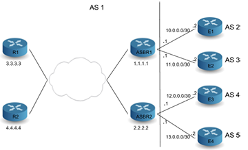
A Centralized EPE Controller can be used to establish iBGP session with R1 and R2. Let’s assume Controller advertises BGP LU routes for E2, i.e., 11.0.0.2/32, with next-hop set to loop-back IP address of ASBR1, that is, 1.1.1.1 and a label 111 to R1 & R2.
switch# show ip bgp 11.0.0.2/32
BGP routing table information for VRF default
Router identifier 3.3.3.3, local AS number 1
BGP routing table entry for 11.0.0.2/32
Paths: 1 available
Local
1.1.1.1 labels [111] from 100.100.100.1 (100.100.100.1)
Origin IGP, metric 0, localpref 100, IGP metric 40, weight 0, received
21:07:07 ago, valid, external, not installed
Rx SAFI: Labels
Tunnel RIB eligible
BGP LU path next-hop will get resolved over an ISIS SR tunnel present on R1 and R2 to reach 1.1.1.1, loop-back IP address of ASBR1.
switch# show tunnel rib brief
Endpoint Tunnel Type Index(es) Metric Metric2 Preference Preference2
----------- ------------ --------- ------- ------- ----------- -----------
1.1.1.1/32 IS-IS SR IPv4 5 40 0 115 0
switch#show bgp labeled-unicast tunnel
Index Endpoint Nexthop/Tunnel Index Interface Labels Contributing Metric
----- -------- -------------------- --------- ------ ------------ ------
1 11.0.0.2/32 IS-IS SR IPv4 (5) - [ 111 ] Yes 0
Metric 2 Pref Pref 2
-------- ---- ------
100 200 0
switch#show isis segment-routing tunnel
Index Endpoint Nexthop Interface Labels
-------- ---------- ------- --------- ----------
5 1.1.1.1/32 6.6.6.6 Ethernet 5 [ 900001 ]
Controller or CLI can be used to install a static label route on ASBR1 such that ingress label 111 have a forwarding action of “POP and forward” to next-hop (11.0.0.2) in MPLS forwarding table.
switch# show mpls lfib route
MPLS forwarding table (Label [metric] Vias) - 20 routes
MPLS next-hop resolution allow default route: False
Via Type Codes:
M - Mpls Via, P - Pseudowire Via,
I - IP Lookup Via, V - Vlan Via,
VA - EVPN Vlan Aware Via, ES - EVPN Ethernet Segment Via,
VF - EVPN Vlan Flood Via, AF - EVPN Vlan Aware Flood Via,
NG - Nexthop Group Via
Source Codes:
S - Static MPLS Route, B2 - BGP L2 EVPN,
B3 - BGP L3 VPN, R - RSVP,
P - Pseudowire, L - LDP,
IP - IS-IS SR Prefix Segment, IA - IS-IS SR Adjacency Segment,
IL - IS-IS SR Segment to LDP, LI - LDP to IS-IS SR Segment,
BL - BGP LU, ST - SR TE Policy,
DE - Debug LFIB
S 111 [100]
via M, 11.0.0.2, pop
payload ipv4, apply egress-acl
interface Ethernet 4
For prefixes to which traffic should be sent over interface connected E2 controller will advertise a BGP route with next-hop being BGP LU prefix and higher local-preference compared to paths advertised by ASBR1 and ASBR2, so that path received from controller will be preferred over paths coming from ASBR1 and ASBR2.
switch# show ip bgp 50.0.0.0/8
BGP routing table information for VRF default
Router identifier 3.3.3.3, local AS number 1
BGP routing table entry for 50.0.0.0/8
Paths: 3 available
Local
11.0.0.2 from 100.100.100.1 (100.100.100.1)
Origin IGP, metric 0, localpref 200, IGP metric 0, weight 0, received 00:00:15
ago, valid, internal, best
Rx SAFI: Unicast
2 100
1.1.1.1 from 1.1.1.1 (1.1.1.1)
Origin IGP, metric 0, localpref 100, IGP metric 0, weight 0, received 00:04:49
ago, valid, internal
Rx SAFI: Unicast
2 200 300
2.2.2.2 from 2.2.2.2 (2.2.2.2)
Origin IGP, metric 0, localpref 100, IGP metric 0, weight 0, received 00:30:38
ago, valid, internal
Rx SAFI: Unicast
This results in pushing two labels on R1, top label is the label corresponding to ISIS SR tunnel to reach ASBR1 and bottom label is the label that corresponds to egress interface. Similarly LU route for12.0.0.0.2 or 13.0.0.2 can be advertised from controller to select egress peer between E3 and E4. This approach provides Egress peer selection on an ingress router R1/R2.
switch# show ip route 50.0.0.0/8
VRF: default
Codes: C - connected, S - static, K - kernel,
O - OSPF, IA - OSPF inter area, E1 - OSPF external type 1,
E2 - OSPF external type 2, N1 - OSPF NSSA external type 1,
N2 - OSPF NSSA external type2, B I - iBGP, B E - eBGP,
R - RIP, I L1 - IS-IS level 1, I L2 - IS-IS level 2,
O3 - OSPFv3, A B - BGP Aggregate, A O - OSPF Summary,
NG - Nexthop Group Static Route, V - VXLAN Control Service,
DH - DHCP client installed default route, M - Martian,
DP - Dynamic Policy Route
B I 50.0.0.0/8 [200/0] via 11.0.0.2/32, BGP LU tunnel index 1
via 6.6.6.6, Ethernet 5, label 900001 111
Inter-AS Option C is an efficient and scalable MPLS IP VPN solution to provide connectivity between two sites of a customer connected to Provider Edge (PE) routers in different ASes. Following diagram shows a typical topology.
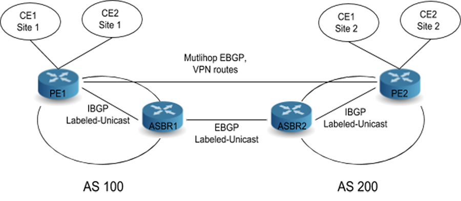
PE1 and ASBR1 and PE2 and ASBR2 distribute loop-back addresses using an IBGP Labeled Unicast (LU) session. ASBR2 advertises system addresses in AS200 to ASBR1 with next-hop as itself over EBGP LU session between them and installing Label swap entry of label sent to ASBR1 (L2) to label received from PE2 (L1) in MPLS forwarding table. ASBR1 further propagates system addresses in AS200 learned from ASBR2 into AS100 or to PE1 using IBGP LU session with next-hop as itself and installing Label swap entry with label advertised to PE1 (L3) to Label received from ASBR2 (L2) in MPLS forwarding table. Similarly ASBR1 sends system addresses in AS100 to ASBR2 over EBGP LU session, ASBR2 forwards them into AS200 or to PE2 using IBGP LU session with itself as next-hop and this would trigger installing appropriate label swap actions into MPLS forwarding table. These advertisements results in the creation of a label switched path from PE1 to PE2.
PE1 and PE2 exchange VPN routes between each other using a Multi hop EBGP session with next-hop being their own loop-back/system addresses. This method eliminates the requirement of storing or sending/receiving VPN routes at ASBR routers. When PE and ASBR routers are non-adjacent, but in the same AS, then LDP or ISIS-SR can be used as a transport label signaling protocol and this would need resolving BGP LU path next-hop over LDP or ISIS-SR tunnel. An IP packet destined to an address in CE1 site 2 is received on PE1 from CE1 site 1 PE1 would need to push 3 labels onto it. Bottom label corresponds to packet destination address in a particular VRF of CE1 site 2 advertised by PE2 to PE1 over Multi hop EBGP session, Middle label belongs to PE2 system address sent by ASBR1 and top label corresponding to ASBR1 system address assigned by transport label signaling protocol.
BGP Selective Route Download allows the learning and advertising of BGP routes without installing them in hardware. The BGP routes are filtered before installation in hardware through the route map definition and routes that are filtered out are flagged as inactive in the Routing Information Base (RIB).
The route map used for filtering is applied only to BGP learned paths and not on locally originated routes, for example, BGP aggregate or redistributed routes. Also, because the BGP routes filtered by Selective Route Download are not active in the RIB, they are not used for recursive resolution, they are not redistributed into other protocols, and they do not contribute to BGP aggregates.
When BGP Selective Route Download is configured, the best path for peer advertisement is chosen based on the following aspects. If received BGP paths exist, then the best of them is advertised to BGP peers, else, the aggregate is preferred if configured and active. If neither BGP paths nor a BGP aggregate is available, then the RIB winner is advertised.
A BGP route reflector is a switch within an autonomous system that forwards route information learned from iBGP peers to other iBGP peers as an alternative to a full-mesh topology. When the switch is configured as a route reflector it can also be configured to preserve the BGP attributes of the reflected routes (next-hop, local preference, and metric) in its route advertisements regardless of outbound BGP policies.
Adds the BGP Nexthop Resolution RIBs feature for EVPN and labeled-unicast address families.
BGP Nexthop Resolution RIBs: EVPN and IPV4/6 Labeled-Unicast Support adds support for user-configured BGP Nexthop Resolution RIB profiles for various BGP-based services such as IP unicast, L3 VPN, EVPN, etcetra. This feature allows an administrator to customize the next hop resolution semantics of BGP routes with an ordered list, or profile, of resolution RIB domains (for example, either tunnel or IP domain). This allows EOS to direct specific services over the specified RIB domains, overriding the default behavior. Further, this feature, through the use of user-defined tunnel RIBs, empowers an administrator to further select a subset of tunneling protocols for specific services.
For IPv4 or IPv6 unicast NLRI received from eBGP, directly connected BGP sessions are resolved by only using connected routes, or system-connected, in the parlance of this feature. This feature does not change this behavior, nor will configuration of a non-default resolution profile affect this behavior.
| Address family | Restriction |
|---|---|
| IPv4/IPv6 unicast (non 6PE) | None. |
| IPv6 unicast 6PE | Only supports tunnel domains*. |
| IPv4/IPv6 unicast (eBGP directly connected) | Only supports system-connected; Not configurable. |
| IPv4/IPv6 VPN | Only supports tunnel domains* and system-connected. |
| IPv4/IPv6 LU | Only supports tunnel domains* and system-connected. |
| EVPN (MPLS) | Only supports tunnel domains* and system-connected. |
| EVPN (VXLAN) | Only supports IP domains+. |
* Tunnel domains refer to tunnel RIBs, e.g. system-colored-tunnel-rib, system-tunnel-rib, or user-defined tunnel RIBs.
+ IP domains are either of system-unicast-rib or system-connected.
In the multi-agent routing protocol model, the BGP agent now supports matching community lists with a logical OR via the route map match community or-results command (same applies for extended and large communities with match extcommunity and match large-community).
Without the or-results portion of the command, the default is to compute the logical AND of all provided community lists. Before, one would need to merge existing community lists into one to do a logical OR:
switch(config)# ip community-list COMMLIST1 permit 1:1
switch(config)# ip community-list COMMLIST2 permit 2:2
! No way to match "COMMLIST1" or "COMMLIST2" in a singel
! route-map sequence match community COMMLIST1 COMMLIST2
switch(config)# ip community-list standard mergedCommunityList permit 1:1
switch(config)# ip community-list standard mergedCommunityList permit 2:2
match community mergedCommunityList
This feature is available only when configuring BGP in the multi-agent routing protocol model.
The EOS Release 4.21.3F introduces support for BGP Flowspec, as defined in RFC5575 and RFC7674. The typical use case is to filter or redirect DDoS traffic on edge routers.
BGP Flowspec rules are disseminated using a new BGP address family. The rules include both matching criteria used to match traffic, and actions to perform on the matching traffic. The rules are programmed into TCAM resources and applied on the ingress ports for which flowspec is enabled.
Added support for hitless rule updates. This enhancement ensures that persistent filtering rules remain active while other filtering rules update, for example, a BGP Peer publishes or withdraws rules.
Added support for configuring BGP Flowspec on subinterfaces. To enable subinterface support, the TCAM profile of the flow-spec feature must include port qualifier size 3 bits (see Flowspec TCAM Profile and Flowspec Policer TCAM Profile below).
Removed EOS Release 4.23.1 limitation to best effort programming.
To redirect to a nexthop, IP RIB must have a route to resolve the specified nexthop. When redirecting to a VRF, a default route for the VRF must be configured and traffic sent to the nexthop for the default route in this VRF.
flow-spec
counters poll interval 30-300 seconds
EOS adds support to use large community lists in the set large community route map set clause.
The Support for Set Large Community List feature allows a large community list to be shared between a number of route maps. Changes to the large community list then affect all route-maps which use this list. This makes applying the same policy change to different inbound and outbound communication easier.
Properties of large communities and how to create large community lists are not be covered as those are described here.
The following commands have been added to route map configuration:
set large-community large-community-list LIST1 [LIST2][additive | delete]
no set large-community large-community-list LIST1 [LIST2][additive | delete]
default set large-community large-community-list LIST1 [LIST2][additive | delete]
The following command replaces the large community value of the contents of the permit sequences of the specified large community list. It is possible to specify more than one large community list to the set clause. In this example, the community values in permit sequences in the lists are concatenated and applies in the set clause.
set large-community large-community-list LIST1 [LIST2]
no set large-community large-community-list LIST1 [LIST2]
default set large-community large-community-list LIST1 [LIST2]
The following command works similarly to the prior command, however, it does not replace communities already set on a route; it concatenates the community values with the values specified in the list. Duplicate communities are only shown once.
default set large-community large-community-list LIST1 [LIST2][additive]
set large-community large-community-list LIST1 [LIST2][additive]
no set large-community large-community-list LIST1 [LIST2][additive]
In the following command, the delete keyword is used. The delete keyword specifies that any large community values in the input matching any of the large community values (or large community value regular expressions) in the specified large community lists are removed.
default set large-community large-community-list LIST1 [LIST2][delete]
set large-community large-community-list LIST1 [LIST2][delete]
no set large-community large-community-list LIST1 [LIST2][delete
Apply the following command to the concerned neighbour which large communities are to be sent, otherwise they are not sent.
neighbour x.x.x.x send-community large
Use the following command to show information about all of the configured route maps.
show route-map
switch# show route-map
route-map rm1 permit 10
Description:
Match clauses:
SubRouteMap:
Set clauses:
set large-community large-community-list lgl1 lgl2
For IPv4 or IPv6 unicast NLRI received from eBGP, directly connected BGP sessions are resolved by only using connected routes, or system-connected, in the parlance of this feature. This feature does not change this behavior, nor will configuration of a non-default resolution profile affect this behavior.
| Address family | Restriction |
|---|---|
| IPv4/IPv6 unicast (non 6PE) | None. |
| IPv6 unicast 6PE | Only supports tunnel domains*. |
| IPv4/IPv6 unicast (eBGP directly connected) | Only supports system-connected; Not configurable. |
| IPv4/IPv6 VPN | Only supports tunnel domains* and system-connected. |
| IPv4/IPv6 LU | Only supports tunnel domains* and system-connected. |
| EVPN (MPLS) | Only supports tunnel domains* and system-connected. |
| EVPN (VXLAN) | Only supports IP domains+. |
* Tunnel domains refer to tunnel RIBs, e.g. system-colored-tunnel-rib, system-tunnel-rib, or user-defined tunnel RIBs.
+ IP domains are either of system-unicast-rib or system-connected.
BGP Add-Path TX, or send, allows for a BGP speaker to advertise multiple paths (instead of a single best-path) for a prefix towards a peering BGP speaker. BGP Add-Path increases path diversity in a network. It restores fast traffic and has efficient link usage through multipathing. This can also be used as a monitoring solution for eligible paths to a monitoring or receiving Add-Path speaker.
Without Add-Path, a sending speaker only sends the best-path for a prefix and a receiving speaker collects all best-path announcements from its peers. The receiving speaker uses only the peer’s address to identify the path.
With Add-Path, the sending speaker can potentially send multiple paths using distinct path-id’s to a peer and the receiver can use to distinguish the multiple paths coming from the same sender.
In symmetric network topology, for the same Equal Cost Multi-Path (ECMP) route programmed at different devices in a switch layer, the various devices can program ECMP next-hops in the Forwarding Equivalence Class (FEC) for that route in varying orders. This could result in inconsistent hashing of traffic for those destination routes at the same layer of switches in the network and could be undesired behavior for certain classes of applications. Ordered FEC is an approach to order the next hops in the FEC of a route based on a network-wide device identifier for each next-hop resulting inconsistent ordering of next hops in the FEC for a route across all switches in a layer.
A BGP router-id can be used as a unique network-wide device identifier and BGP paths received from various peers for a BGP ECMP route can have their paths and subsequently, next-hops sorted based on the corresponding peer’s router-id. Ordered Next Hops in the FEC feature would use the BGP router-id to achieve a consistent ordering of next hops in the FEC for a route. This feature is available with multi-agent routing protocol models.
EOS supports mixed IPv4 and IPv6 next hops in a network. An ECMP FEC may have an IPv4 primary route with a secondary IPv6 next hop or an IPv6 route with a secondary IPv4 next hop.
Use the following configuration commands to implement Ordered FEC solution for BGP routes.
switch(config)# router bgp 100
switch(config-router-bgp)# address-family ipv4
switch(config-router-bgp)# bgp bestpath tie-break router-id
switch(config-router-bgp)#
switch(config)# router general
switch(config-router-general)# rib fib fec ecmp ordered
switch(config-router-general)#
The show ip route fec command displays if the next-hops in the FEC of a route have been ordered. The output below indicate the show command output before enabling the Ordered FEC solution on the device, and after enabling it. The show ip bgp command output is also included to correlate next hop with corresponding router-id of the peer that the path was received from.
switch# show ip bgp 1.0.16.0
BGP routing table information for VRF default
Router identifier 0.0.0.1, local AS number 1
BGP routing table entry for 1.0.16.0/24
Paths: 8 available
30
1.0.10.2 from 1.0.10.2 (10.0.1.1)
Origin EGP, metric 0, localpref 100, IGP metric 1, weight 0, received 00:01:53 ago, valid, external, ECMP head, ECMP, best, ECMP contributor
Rx SAFI: Unicast
10
1.0.8.2 from 1.0.8.2 (10.0.4.1)
Origin EGP, metric 0, localpref 100, IGP metric 1, weight 0, received 00:01:55 ago, valid, external, ECMP, ECMP contributor
Rx SAFI: Unicast
20
1.0.9.2 from 1.0.9.2 (10.0.3.1)
Origin EGP, metric 0, localpref 100, IGP metric 1, weight 0, received 00:01:54 ago, valid, external, ECMP, ECMP contributor
Rx SAFI: Unicast
40
1.0.11.2 from 1.0.11.2 (10.0.8.1)
Origin EGP, metric 0, localpref 100, IGP metric 1, weight 0, received 00:01:52 ago, valid, external, ECMP, ECMP contributor
Rx SAFI: Unicast
50
1.0.12.2 from 1.0.12.2 (10.0.2.1)
Origin EGP, metric 0, localpref 100, IGP metric 1, weight 0, received 00:01:52 ago, valid, external, ECMP, ECMP contributor
Rx SAFI: Unicast
60
1.0.13.2 from 1.0.13.2 (10.0.5.1)
Origin EGP, metric 0, localpref 100, IGP metric 1, weight 0, received 00:01:51 ago, valid, external, ECMP, ECMP contributor
Rx SAFI: Unicast
70
1.0.14.2 from 1.0.14.2 (10.0.6.1)
Origin EGP, metric 0, localpref 100, IGP metric 1, weight 0, received 00:01:50 ago, valid, external, ECMP, ECMP contributor
Rx SAFI: Unicast
80
1.0.15.2 from 1.0.15.2 (10.0.7.1)
Origin EGP, metric 0, localpref 100, IGP metric 1, weight 0, received 00:01:49 ago, valid, external, ECMP, ECMP contributor
Rx SAFI: Unicast
switch#
switch# show ip ro 1.0.16.0 fec
FEC ID 4294967334, used by 100 IPv4 prefixes and 0 IPv6 prefixes
Next hops:
via 1.0.8.2, Ethernet8
via 1.0.9.2, Ethernet9
via 1.0.10.2, Vlan2317
via 1.0.11.2, Vlan2836
via 1.0.12.2, Vlan2043
via 1.0.13.2, Ethernet4
via 1.0.14.2, Vlan2000
via 1.0.15.2, Vlan2191
switch#
switch(config)# router general
switch(config-router-general)# rib fib fec ecmp ordered
switch(config-router-general)# end
switch# show ip route 1.0.16.0 fec
FEC ID 4294967334, used by 100 IPv4 prefixes and 0 IPv6 prefixes
Next hops (ordered):
via 1.0.10.2, Vlan2317
via 1.0.12.2, Vlan2043
via 1.0.9.2, Ethernet9
via 1.0.8.2, Ethernet8
via 1.0.13.2, Ethernet4
via 1.0.14.2, Vlan2000
via 1.0.15.2, Vlan2191
via 1.0.11.2, Vlan2836
Example
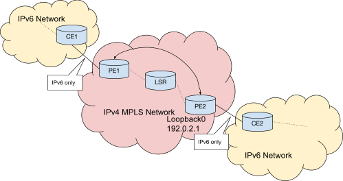
BGP Monitoring Protocol (BMP) allows a monitoring station to connect to a router and collect all BGP announcements received from the BGP peers of the router. BGP sends announcements to the monitoring station as BMP Route Monitoring messages generated from path information in the BGP internal tables on the router. A BMP speaker may choose to send either Adj-Rib-In routes or Loc-Rib routes, or both.
The router sends unidirectional BMP messages to the monitoring station and does not send monitoring messages from the monitoring station to the router. The router configuration controls the information sent to a monitoring station.
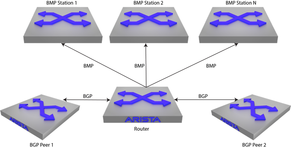
The switch supports one BGP instance, which is associated with a specified Autonomous System (AS). To other BGP peers, the AS number uniquely identifies the network to which the switch belongs. Arista switches support four-byte AS numbers as described in RFC 4893. Four-byte AS number capability is communicated to BGP peers in OPEN messages. When communicating with a BGP peer which does not support four-byte AS numbers, the switch will replace AS numbers greater than 65535 with the well-known two-byte AS number 23456 (also called AS_TRANS), and encode the actual four-byte AS numbers using the AS4_PATH attribute.
The switch must be in router-BGP configuration mode to run BGP configuration commands. The router bgp command places the switch in the router-BGP configuration mode for creating a BGP instance if one was not previously created. BGP configuration commands apply globally to the BGP instance.
This command places the switch in router-BGP configuration mode. It also creates a BGP instance in AS 50 if an instance was not previously created.
switch(config)# router bgp 50
switch(config-router-bgp)#
When a BGP instance exists, the router bgp command must include its autonomous system. Any attempt to create a second instance results in an error message.
This command attempts to open a BGP instance with a different AS number from that of the existing instance. The switch displays an error and stays in global configuration mode.
switch(config)# router bgp 100
% BGP is already running with AS number 50
switch(config)#
IPv6 VRF support in EOS allows application of a BGP configuration to a single VRF instance, overriding global commands. To apply VRF-specific BGP configuration, use the vrf command within router-BGP configuration mode to enter BGP VRF configuration mode. IPv6 BGP VRF configuration is performed in the VRF submode of the router-BGP configuration mode. This submode is also where a Route Distinguisher (RD) is configured for a VRF on switches running Ethernet VPN (EVPN): use the rd (Router-BGP VRF and VNI Configuration Modes) command to configure an RD for a VRF.
switch(config)# router bgp 1
switch(config-router-bgp)# vrf purple
switch(config-router-bgp)#
switch(config-router-bgp-vrf-purple)# router-id 1.1.1.1
switch(config-router-bgp-vrf-purple)# neighbor 2001:0DB8:8c01::1 remote-as 16
switch(config-router-bgp-vrf-purple)# address-family ipv6
switch(config-router-bgp-vrf-purple-af)# neighbor 2001:0DB8:8c01::1 activate
switch(config-router-bgp-vrf-purple-af)#
switch(config-router-bgp-vrf-purple)# rd 530:12
switch(config-router-bgp-vrf-purple)#
RCF functions support in EOS allows application of a BGP configuration to filter routes and update route attributes. RCF functions can be configured for inbound and outbound updates on BGP neighbors under the IPv4 unicast, IPv6 unicast, IPv4 labeled unicast, and IPv6 labeled unicast address families.
switch(config)# router bgp 64500
switch(config-router-bgp)# address-family ipv4
switch(config-router-bgp-af)# neighbor 192.168.0.1 rcf in INBOUND_POLICY()
switch(config-router-bgp-af)# neighbor 192.168.0.1 rcf out OUTBOUND_POLICY()
switch(config)# router bgp 64500
switch(config-router-bgp)# address-family ipv6 labeled-unicast
switch(config-router-bgp-af-label)# neighbor 192.168.0.1 rcf in LU_INBOUND_POLICY()
switch(config-router-bgp-af-label)# neighbor 192.168.0.1 rcf out LU_OUTBOUND_POLICY()
switch(config)# router bgp 64500
switch(config-router-bgp)# redistribute connected rcf CONNECTED_POLICY()
switch(config-router-bgp)# redistribute static rcf STATIC_POLICY()
switch(config)# router bgp 64500
switch(config-router-bgp)# redistribute isis level-1 rcf ISIS_LEVEL_1_POLICY()
switch(config-router-bgp)# redistribute isis level-2 rcf ISIS_LEVEL_2_POLICY()
switch(config-router-bgp)# redistribute isis level-1-2 rcf ISIS_LEVEL_1_2_POLICY()
Static neighbors may belong to a static peer group, allowing them to be configured as a group. Configuration applied to an individual member of a static peer group overrides the group configuration for that peer. Dynamic neighbors must belong to a dynamic peer group, and can only be configured as a group.
The neighbor remote-as command connects the switch with a peer, establishing a static neighbor.
Once established, a static neighbor may be added to an existing peer group. Any configuration applied to the peer group then is inherited by the neighbor, unless a conflicting configuration has been entered for that peer. Settings applied to a member of the peer group override group settings.
switch(config)# router bgp 50
switch(config-router-bgp)# neighbor 10.1.1.14 remote-as 50
switch(config-router-bgp)#
switch(config)# router bgp 50
switch(config-router-bgp)# neighbor 192.168.2.5 remote-as 100
switch(config-router-bgp)#
The bgp listen range command specifies a range of IPv4 addresses from which the switch will accept incoming dynamic BGP peering requests, and creates the named dynamic peer group to which those peers belong. Dynamic BGP neighbors are peers which have not been manually established, but are accepted into a dynamic peer group when the switch receives a peering request from them.
Dynamic peers cannot be configured individually, but inherit any configuration that is applied to the peer group to which they belong. Peering relationships with dynamic peers are terminated if the peer group is deleted.
switch(config)# router bgp 50
switch(config-router-bgp)# bgp listen range 192.168.2.0/24 peer-group brazil remote-as 50
switch(config-router-bgp)#
The show ip bgp summary and show ip bgp neighbors commands display neighbor connection status.
switch# show ip bgp summary
BGP summary information for VRF default
BGP router identifier 192.168.104.2, local AS number 50
Neighbor Status Codes: m - Under maintenance
Neighbor V AS MsgRcvd MsgSent InQ OutQ Up/Down State PfxRcd PfxAcc
192.168.2.5 4 100 198 281 0 0 03:11:31 Estab 12 12
switch#
A static BGP peer group is a collection of BGP neighbors which can be configured as a group. Once a static peer group is created, the group name can be used as a parameter in neighbor configuration commands, and the configuration will be applied to all members of the group. Neighbors added to the group will inherit any settings already created for the group. Static peer group members may also be configured individually, and the settings of an individual neighbor in the peer group override group settings for that neighbor.
When the default form of a BGP configuration command is entered for a member of a static peer group, the peer inherits that configuration from the peer group.
A static peer group is created with the neighbor peer group (create) command, or by using the bgp listen range command to accept dynamic peering requests. Once a static peer group has been created, static neighbors can be manually added to the group by using the neighbor peer group (neighbor assignment) command. The neighbor peer group (neighbor assignment) command removes a neighbor from a static peer group.
The neighbor peer group (create) command will delete a static peer group. When a peer group is deleted, the members of that group revert to their individual configurations, or to the system default for any attributes that have not been specifically configured for that peer.
switch(config)# router bgp 50
switch(config-router-bgp)# neighbor akron peer group
switch(config-router-bgp)#
switch(config-router-bgp)# neighbor 1.1.1.1 peer group akron
switch(config-router-bgp)# neighbor 2.2.2.2 peer group akron
switch(config-router-bgp)#
switch(config-router-bgp)# neighbor akron remote-as 109
switch(config-router-bgp)# neighbor akron out-delay 101
switch(config-router-bgp)# neighbor akron maximum-routes 12000
switch(config-router-bgp)# no neighbor 1.1.1.1 out-delay
switch(config-router-bgp)#
A dynamic BGP peer group is a collection of BGP neighbors in a specified address range which makes a peer request to the switch. Members of dynamic peer group are configured in groups and not as individuals. A dynamic peer group name is used as a parameter to apply the configuration across all the members in the group. Neighbors joining the group inherit any settings already created for the group.
The bgp listen range command is used to create a dynamic peer group. This command identifies the BGP peering request from a range of IP address, and names the dynamic peer group to which those peers belong to. The bgp listen range command can be configured to accept a peering request from a single AS number or to accept peer request from the range of AS numbers. To accept the request from the range of AS numbers use the peer filter option in the command as shown. If the peer filter referred by the bgp listen range command does not exist, or if the filter exists but has no match commands, it will accept any AS number.
To delete a dynamic peer group, use the no or default form of the bgp listen range command. All peering relationships with group members are terminated when the dynamic peer group is deleted.
switch(config)# router bgp 1
switch(config-router-bgp)# bgp listen range 192.0.2.0/24 peer-group brazil remote-as 5
switch(config-router-bgp)#
switch(config)# router bgp 1
switch(config-router-bgp)# bgp listen range 192.0.2.0/24 peer-group brazil peer-filter group-1
switch(config-router-bgp)#
The show ip bgp peer-group command displays the source of a listen range’s remote AS number definition as shown.
switch(config-router-bgp)# show ip bgp peer-group
BGP peer-group is brazil
BGP version 4
Listen-range subnets:
VRF default:
192.0.2.0/24, remote AS 5
192.0.2.0/24, peer filter group1
switch(config-router-bgp)#
A peer filter defines a set of rules to decide whether to accept or reject the incoming peer request based on the peer’s attributes. The peer filter is defined using a sequence number and a match statement, and supports one new match statement for matching against a range of BGP AS numbers. A peer filter is defined in peer filter configuration mode as shown. The peer filter command supports only matching AS ranges. Unlike route maps, peer filters do not support sets, continues or subroutines.
To delete a peer filter, use the no peer filter or default peer filter commands.
switch(config)# peer-filter group1
switch(config-peer-filter-group1)# 10 match as-range 1-4294967295 result accept
switch(config-peer-filter-group1)#
switch(config)# peer-filter group2
switch(config-peer-filter-group2)# 10 match as-range 65008-65009 result reject
switch(config-peer-filter-group2)# 20 match as-range 65000-651000 result accept
switch(config-peer-filter-group2)#
switch(config)# peer-filter group3
switch(config-peer-filter-group3)# 10 match as-range 65003 result accept
switch(config-peer-filter-group3)# 20 match as-range 65007 result accept
switch(config-peer-filter-group3)# 30 match as-range 65009 result accept
switch(config-peer-filter-group3)#
The show peer-filter command displays the peer filter definition.
switch(config)# show ip bgp peer-group3
peer-filter group3
10 match as-range 65003 result accept
20 match as-range 65007 result accept
30 match as-range 65009 result accept
switch(config)#
BGP predates the use of IPv6, and BGP configuration assumes IPv4 connections by default. The following additional steps are used to configure IPv6 BGP neighbors.
By default, the switch does not negotiate or advertise IPv6 BGP routes. In order to establish a session with an IPv6 neighbor, it must be made active in the IPv6 address family. The ipv6-unicast option of the bgp default command causes the switch to send IPv6 capability messages and all network advertisements with IPv6 prefixes to all BGP neighbors. The neighbor activate command issued in IPv6 address family configuration mode does the same for a single BGP neighbor.
switch(config)# router bgp 11
switch(config)# address-family ipv6
switch(config-router-bgp-af)# bgp default ipv6-unicast
switch(config-router-bgp-af)# exit
switch(config-router-bgp)#
switch(config)# router bgp 11
switch(config)# address-family ipv6
switch(config-router-bgp-af)# neighbor 2001:0DB8:8c01::1 activate
switch(config-router-bgp-af)# exit
switch(config-router-bgp)#
The switch supports the exchange of IPv4 NLRIs with IPv6 neighbors. To enable this feature for all IPv6 neighbors, use the ipv4-unicast transport ipv6 option of the bgp default command in the IPv4 address family configuration mode. To enable it for a single IPv6 neighbor, use the neighbor activate command for that neighbor in the IPv4 address family configuration mode.
To send IPv4 NLRIs to IPv6 neighbors, the IPv4 next-hop address must also be communicated. To explicitly configure an IPv4 next hop to send to a specific IPv6 neighbor, use the neighbor local-v4-addr command. In some network configurations, the switch can also be configured to automatically determine the best IPv4 next-hop address for an individual IPv6 neighbor or for all neighbors in the VRF using the neighbor auto-local-addr command.
switch(config)# router bgp 11
switch(config-router-bgp)# address-family ipv4
switch(config-router-bgp-af)# bgp default ipv4-unicast transport ipv6
switch(config-router-bgp-af)# exit
switch(config-router-bgp)# neighbor indianapolis auto-local-addr
switch(config-router-bgp)#
switch(config)# router bgp 11
switch(config-router-bgp)# address-family ipv4
switch(config-router-bgp-af)# neighbor 2001:0DB8:8c01::1 activate
switch(config-router-bgp-af)# exit
switch(config-router-bgp)# neighbor 2001:0DB8:8c01::1 local-v4-addr 10.7.5.11
switch(config-router-bgp)#
BGP neighbors maintain connections by exchanging KEEPALIVE, UPDATE, and NOTIFICATION messages. Neighbors that do not receive a message from a peer within a specified period (hold time) close the BGP session with that peer. Hold time is typically three times the period between scheduled KEEPALIVE messages. The default keepalive period is 60 seconds; default hold time is 180 seconds.
The timers bgp command configures the hold time and keepalive period. A peer retains its BGP connections indefinitely when its hold time is zero.
switch(config-router-bgp)# timers bgp 15 45
switch(config-router-bgp)#
The show ip bgp neighbors command displays the hold time.
switch# show ip bgp neighbors 10.100.100.2
BGP neighbor is 10.100.100.2, remote AS 100
BGP version 4, remote router ID 192.168.100.13, VRF default
Negotiated BGP version 4
Last read 00:00:05, last write 00:00:05
Hold time is 45, keepalive interval is 15 seconds <= hold time
Configured hold time is 45, keepalive interval is 15 seconds
Connect timer is inactive
Idle-restart timer is inactive
BGP state is Established, up for 04:44:05
Number of transitions to established: 11
Last state was OpenConfirm
Last event was RecvKeepAlive
Last sent notification:Cease/administrative reset, Last time 04:44:09
Last rcvd notification:Cease/peer de-configured, Last time 2d02h, First time 7d08h, Repeats 1
Neighbor Capabilities:
Multiprotocol IPv4 Unicast: advertised and received and negotiated
Four Octet ASN: advertised and received
<-------OUTPUT OMITTED FROM EXAMPLE------->
switch#
The neighbor maximum-routes command determines the number of BGP routes the switch accepts from a specified neighbor. The switch disables peering with the neighbor when this number is exceeded.
Example
switch(config-router-bgp)# neighbor 192.168.18.24 maximum-routes 15000
switch(config-router-bgp)#
Participating BGP routers within an AS communicate eBGP-learned routes to all of their peers; they do not re-advertise iBGP-learned routes within the AS to prevent routing loops. Although a fully meshed network topology ensures that all AS members share routing information, this topology can result in high volumes of iBGP messages when scaled. Alternatively, one or more routers can be configured as route reflectors in larger networks.
A route reflector re-advertises routes learned through iBGP to a group of BGP neighbors within the AS, replacing the function of a fully meshed topology. The neighbor route-reflector-client command configures the switch to act as a route reflector and configures the specified neighbor as a client. The bgp client-to-client reflection command enables client-to-client reflection.
Cluster IDs When using route reflectors, an AS is divided into clusters. A cluster contains at least one route reflector and a group of clients to which they re-advertise route information. A cluster may contain multiple route reflectors to provide redundancy protection. Each reflector has a cluster ID. When the cluster has a single route reflector, the cluster ID is its router ID. When a cluster has multiple route reflectors, a 4-byte cluster ID is assigned to all route reflectors in the cluster, allowing them to recognize updates from other cluster reflectors. The command configures the cluster ID in a cluster with multiple route reflectors.
Attribute Preservation Outbound BGP policies can rewrite the BGP attributes (next-hop, local preference and metric) of routes advertised by a route reflector. To configure the route reflector to preserve these attributes regardless of policy (unless those policies are included in a route map), use the bgp route-reflector preserve-attributes command. To include route attributes at all times (even contrary to policies included in route maps), use the always option of the command.
Client-to-client Reflection Usually the clients of a route reflector are not interconnected, and any routes learned by a client are mirrored to other clients and re-advertised within the AS by the route reflector. If the clients of a route reflector are fully meshed, routes received from a client do not need to be mirrored to other clients. In this case, client-to-client reflection should be disabled using the bgp client-to-client reflection command.
switch(config-router-bgp)# neighbor 172.72.14.5 route-reflector-client
switch(config-router-bgp)# bgp cluster-id 172.22.30.101
switch(config-router-bgp)# bgp route-reflector preserve-attributes
switch(config-router-bgp)#
switch# show bgp instance
BGP instance information for VRF default
BGP Local AS: 64512, Router ID: 1.1.4.1
Total peers: 14
Configured peers: 14
UnConfigured peers: 0
Disabled peers: 4
Established peers: 9
Graceful restart helper mode enabled
Attributes of reflected routes are preserved
End of rib timer timeout: 00:05:00
BGP Convergence timer is inactive
BGP Convergence information:
BGP has converged: yes, Time taken to converge: 00:05:44
Outstanding EORs: 0, Outstanding Keepalives: 0
Convergence timeout: 00:10:00
switch#
The primary function of external peers is to distribute routes they learn from their peers. Internal peers receive route updates without distributing them. External peers receive route updates, then distribute them to internal and external peers.
Local preference is a metric that iBGP sessions use to select an external route. Preferred routes have the highest local preference value. UPDATE packets include this metric in the LOCAL_PREF field.
The neighbor export-localpref command specifies the LOCAL_PREF that the switch sends to an internal peer. The command overrides previously assigned preferences and has no effect on external peers.
Example
switch(config-router-bgp)# neighbor 10.1.1.45 export-localpref 200
switch(config-router-bgp)#
The neighbor import-localpref command assigns a local preference to routes received through UPDATE packets from an external peer. This command has no effect when the neighbor is an internal peer.
switch(config-router-bgp)# neighbor 172.16.5.2 import-localpref 50
switch(config-router-bgp)#
The show ip bgp command displays the LOCAL_PREF value for all listed routes.
switch# show ip bgp
BGP routing table information for VRF default
Router identifier 192.168.100.23, local AS number 64512
Route status codes: s - suppressed, * - valid, > - active, # - not installed, E - ECMP head, e - ECMP S - Stale, c - Contributing to ECMP, b - backup, L - labeled-unicast
Origin codes: i - IGP, e - EGP, ? - incomplete
AS Path Attributes: Or-ID - Originator ID, C-LST - Cluster List, LL Nexthop - Link Local Nexthop
Network Next Hop Metric LocPref Weight Path
* >Ec 10.10.20.0/24 192.168.31.3 0 400 0 64521 i
switch#
Graceful BGP restart allows a BGP speaker with separate control plane and data plane processing to continue forwarding traffic during a BGP restart. Its neighbors (receiving speakers) may retain routing information from the restarting speaker while a BGP session with it is being re-established, reducing route flapping.
Arista switches can act as helpers (receiving speakers) for graceful BGP restart with neighbors that advertise graceful restart capability.
Graceful restart helper mode is enabled by default, but can be turned off globally with the graceful-restart-helper command. Per-peer configuration takes precedence over the global configuration.
switch(config-router-bgp)# no graceful-restart-helper
switch(config-router-bgp)#
switch(config-router-bgp)# no neighbor 192.168.32.5 graceful-restart-helper
switch(config-router-bgp)#
Peers with graceful restart capability advertise a restart time value as an estimate of the time it will take them to restart a BGP session. When a BGP session with a restarting speaker goes down, the switch (receiving speaker) marks routes from that peer as stale and starts the restart timer. If the session with the peer is not re-established before the restart time runs out, the switch deletes the stale routes from that peer. If the session is re-established within that time, the stale path timer is started. If the stale paths are not updated by the restarting speaker before the stale path time runs out, they are deleted. The maximum time these stale paths are retained after the BGP session is re-established is 300 seconds by default, but can be configured using the graceful-restart stalepath-time command.
Example
switch(config-router-bgp)# graceful-restart stalepath-time 500
switch(config-router-bgp)#
Route maps are used in BGP to directly filter IPv4 unicast routes. The neighbor route-map (BGP) command applies a route map to inbound or outbound BGP routes. To display the route maps associated with a specific BGP neighbor, use the show ip bgp neighbors command.
The redistribution of BGP unicast routes into multicast address families allows the network to take a different path for the multicast traffic. It allows redistribution of IPv4 unicast routes into the IPv4 multicast address family and IPv6 unicast routes into the IPv6 multicast address family.
The following command configures the redistribution of IPv4 unicast routes into IPv4 multicast address family in both default and non-default VRF.
switch(config-router-bgp)# address-family ipv4 multicast
switch(config-router-bgp-af)# route input address-family ipv4 unicast rcf onePfx()
bgprtr1(config-router-multicast)# show bgp ipv4 unicast
BGP routing table information for VRF default
Router identifier 1.1.1.1, local AS number 100
Route status codes: s - suppressed, * - valid, > - active, E - ECMP head, e - ECMP
S - Stale, c - Contributing to ECMP, b - backup, L - labeled-unicast
% - Pending BGP convergence
Origin codes: i - IGP, e - EGP, ? - incomplete
RPKI Origin Validation codes: V - valid, I - invalid, U - unknown
AS Path Attributes: Or-ID - Originator ID, C-LST - Cluster List, LL Nexthop - Link Local Nexthop
Network Next Hop Metric AIGP LocPref Weight Path
* > 10.10.10.1/32 1.1.1.2 0 - 100 0 200 i
* > 10.10.20.1/32 1.1.1.2 0 - 100 0 200 i
The following command shows BGP IPv4 multicast output, when a RCF function filters 10.10.20.1/32.
bgprtr1# show bgp ipv4 multicast
BGP routing table information for VRF default
Router identifier 1.1.1.1, local AS number 100
Route status codes: s - suppressed, * - valid, > - active, E - ECMP head, e - ECMP
S - Stale, c - Contributing to ECMP, b - backup, L - labeled-unicast
% - Pending BGP convergence
Origin codes: i - IGP, e - EGP, ? - incomplete
AS Path Attributes: Or-ID - Originator ID, C-LST - Cluster List, LL Nexthop - Link Local Nexthop
Network Next Hop Metric AIGP LocPref Weight Path
* > 10.10.20.1/32 1.1.1.2 - - - 0 ?
Example
switch(config)# ip prefix-list PL_1 permit 10.1.2.5/24
switch(config)# ip prefix-list PL_1 permit 10.2.5.1/28
switch(config)#
switch(config)# route-map MAP_1 permit
switch(config-route-map-MAP_1)# match ip address prefix-list PL_1
switch(config-route-map-MAP_1)# set community 500
switch(config-route-map-MAP_1)# exit
switch(config)#
switch(config)# ip community-list CL_1 permit 500
switch(config)#
BGP extended communities identify routes for VRFs or for Link BandWidth (LBW). Extended community clauses utilize Route Target (RTt) and Site of Origin Options (SOO):
An AS path access list is a named list of permit and deny statements which use regular expressions to filter BGP routes based on their AS path attribute. AS path access lists are created using the ip as-path access-list command, and are applied using a route map match clause with the name of the access list as a parameter.
Example
switch(config)# ip as-path access-list as_list3 permit _3
switch(config)# route-map MAP_3 permit
switch(config-route-map-MAP_3)# match as-path as_list3
switch(config-route-map-MAP_3)# set community 300
switch(config-route-map-MAP_3)# exit
switch(config)# router bgp 1
switch(config-router-bgp)# neighbor 192.68.14.5 route-map MAP_3 in
switch(config-router-bgp)#
The Generalized TTL Security Mechanism (GTSM) uses a packet's Time to Live (TTL) (IPv4) or Hop Limit (IPv6) to protect BGP peering sessions from Denial-of-Service (DoS) attacks based on forged protocol packets.
An IP packet received from a BGP peer is discarded when its current TTL value is less than (255-n) where n is the configured maximum number of hops to the peer. Use the neighbor ttl maximum-hops command to configure the maximum hop count.
A BGP neighbor advertises routes it can reach through UPDATE packets. The network (BGP) command specifies a prefix that the switch advertises as a route originating from its AS.
The configuration clears the host portion of addresses entered in network commands. For example, 192.0.2.4/24 is stored as 192.0.2.0/24.
Example
switch(config-router-bgp)# network 10.5.8.0/24
switch(config-router-bgp)#
By default, BGP will advertise only those routes that are active in the switch’s RIB. This can contribute to dropped traffic. If a preferred route is available through another protocol (like OSPF), the BGP route will become inactive and not be advertised; if the preferred route is lost, there is no available route to the affected peers. Advertising inactive BGP routes minimizes traffic loss by providing alternative routes.
The bgp advertise-inactive command causes BGP to advertise inactive routes to BGP neighbors. Inactive route advertisement is configured globally, but the global setting can be overridden on a per-VRF basis.
switch(config-router-bgp)# bgp advertise-inactive
switch(config-router-bgp)#
switch(config-router-bgp)# vrf purple
switch(config-router-bgp-vrf-purple)# no bgp advertise-inactive
switch(config-router-bgp-vrf-purple)#
The redistribute (BGP) command advertises the routes learned through IS-IS routes into the BGP network. It also allows the user to selectively advertise some routes and modify route attributes before advertising using route maps.
The command is available in both address-family mode and router BGP mode, but the command is rejected if configured in both address-family mode and router mode at the same time.
While redistributing IS-IS routes into BGP, the Level-1 or Level-2 keyword can be used to selectively redistribute Level-1 routes or Level-2 routes into BGP. The keyword is optional, and defaults to Level-2 when not configured.
Use the show ipv6 bgp command to verify that routes are advertised with correct attributes.
switch(config)# router bgp 1
switch(config-router-bgp)# address-family ipv4
switch(config-router-bgp-af)# redistribute isis level-1 route-map isis-to-bgp-v4
switch(config-router-bgp-af)#
switch(config)# router bgp 1
switch(config-router-bgp)# redistribute isis level-1 route-map isis-to-bgp
switch(config-router-bgp)#Routes learned through the OSPF protocol can be redistributed into the BGP domain and advertised by BGP. To redistribute OSPF routes into BGP, use the redistribute (BGP) command. By default, redistribute ospf will redistribute only internal OSPF routes into BGP; the command must be issued separately with additional parameters for each type of OSPF route that is to be redistributed.
switch(config)# router bgp 1
switch(config-router-bgp) #redistribute ospf
switch(config-router-bgp)#
switch(config)# router bgp 1
switch(config-router-bgp)# redistribute ospf internal
switch(config-router-bgp)# redistribute ospf external
switch(config-router-bgp)# redistribute ospf nssa-external
switch(config-router-bgp)#
Aggregation combines the characteristics of multiple routes into a single route for advertisement by the BGP speaker. Aggregation can reduce the amount of information that a BGP speaker is required to store and transmit when advertising routes to other BGP speakers. Aggregation options affect the attributes associated with the aggregated route, the advertisement of the contributor routes that comprise the aggregate, and which contributor routes are included.
Aggregate routes are created with the aggregate-address command, which takes an IP subnet as an argument; any routes configured on the switch that lie within that subnet then become contributors to the aggregate. Note that on Arista switches the BGP aggregate route becomes active if there are any available contributor routes on the switch, regardless of the originating protocol. This includes routes configured statically.
BGP speakers display aggregate routes that they create as null routes (with one exception: if all the contributors to the aggregate have the same BGP path attributes, then the BGP aggregate copies those attributes and is no longer a null route). Aggregate routes are advertised into the BGP autonomous system and redistributed automatically, and their redistribution cannot be disabled. BGP neighbors display inbound aggregate routes as normal BGP routes. Null routes are displayed with the show ip route command. Display normal BGP routes (and null aggregate routes) with the show ip bgp and show ip route commands.
The aggregate-address command provides the following aggregate route options:
When the command includes as-set, the aggregate route’s AS_SET attribute contains the AS numbers of contributor routes. This can help BGP neighbors to prevent loops by rejecting aggregate routes that include their AS number in the AS_SET.
When the command does not include as-set, the aggregate route’s ATOMIC_AGGREGATE attribute is set and the AS_PATH attribute does not include AS numbers of contributing routes.
Example
switch(config)# router bgp 1
switch(config-router-bgp)# aggregate-address 10.16.48.0/20 as-set
switch(config-router-bgp)# exit
switch(config)#
switch(config)# route-map map1 permit 10
switch(config-route-map-map1)# set local-preference 40
switch(config-route-map-map1)# exit
switch(config)# router bgp 1
switch(config-router-bgp)# aggregate-address 10.16.48.0/20 attribute-map map1
switch(config-router-bgp)# exit
switch(config)#
switch(config)# route-map matchmap permit 10
switch(config-route-map-matchmap)# match ip address prefix-list agglist
switch(config-route-map-matchmap)# exit
switch(config)# router bgp 1
switch(config-router-bgp)# aggregate-address 1.1.0.0/16 summary-only match-map matchmap
switch(config-router-bgp)#
The match-map parameter in the aggregate-address command advertises the route(s) denied in match-map.
When configured, this feature introduces the ability to match on the following parameters:
The attributes that are currently supported for matching on BGP aggregate contributors are community, local-preference, prefix, next-hop,route-type.
switch(config-route-map-test)# match aggregate-role contributor
The match aggregate-role contributor clause only works with outbound policies.
Example
switch(config)# ip community-list BLUE permit 65536:100
switch(config)# route-map OUTBOUND_POLICY permit 10
switch(config-route-map-OUTBOUND_POLICY)# match aggregate-role contributor
switch(config-route-map-OUTBOUND_POLICY)# set community community-list BLUE
!
switch(config)# route-map OUTBOUND_POLICY permit 20
switch(config-route-map-OUTBOUND_POLICY)# description “Permit the routes rejected by seq10"
!
switch(config)# router bgp 65536
switch(config-router-bgp)# aggregate-address 203.0.113.0/24
switch(config-router-bgp)# neighbor 192.0.2.1 route-map OUTBOUND_POLICY out
switch(config-router-bgp)#
To match contributors which contribute only to a BGP aggregate with specific attributes (say communities) and set attributes (say communities again) on said contributor, add an outbound policy with the clause:
switch(config-route-map-test)# match aggregate-role contributor aggregate-attributes MATCH_AGG_COLOR
switch(config)# route-map MATCH_AGG_COLOR
switch(config-route-map-MATCH_AGG_COLOR)# match community RED
Add an aggregate definition to explicitly set the desired attributes on the aggregate of interest:
switch(config)# route-map AGG_SET_COLOR
switch(config-route-map-AGG_SET_COLOR)# set community community-list RED
!
switch(config)# router bgp 65536
switch(config-router-bgp)# aggregate-address 203.0.113.0/24
switch(config-router-bgp)# aggregate-address 203.0.113.0/24 attribute-map AGG_SET_COLOR
The route map referenced by the match aggregate-role contributor aggregate-attributes clause discards all set operations.
switch(config)# ip community-list BLUE permit 65536:100
switch(config)# ip community-list RED permit 65536:200
!
switch(config)# route-map AGG_SET_COLOR
switch(config-route-map-AGG_SET_COLOR)# set community community-list RED
!
switch(config-route-map-AGG_SET_COLOR)# route-map MATCH_AGG_COLOR
switch(config-route-map-MATCH_AGG_COLOR)# match community RED
!
switch(config-route-map-MATCH_AGG_COLOR)# route-map OUTBOUND_POLICY permit 10
switch(config-route-map-OUTBOUND_POLICY)# match aggregate-role contributor aggregate-attributes MATCH_AGG_COLOR
switch(config-route-map-OUTBOUND_POLICY)# set community community-list BLUE
!
switch(config-route-map-OUTBOUND_POLICY)# route-map OUTBOUND_POLICY permit 20
switch(config-route-map-OUTBOUND_POLICY)# description “Permit the routes rejected by seq10”
!
switch(config-route-map-OUTBOUND_POLICY)# router bgp 65536
switch(config-router-bgp)# aggregate-address 203.0.113.0/24 attribute-map AGG_SET_COLOR
switch(config-router-bgp)# neighbor 192.0.2.1 route-map OUTBOUND_POLICY out
switch(config-router-bgp)#
This match clause supports the invert-result modifier. When applied, invert-result inverts the result of the match clause to which it is applied.
switch(config-route-map-test)# match invert-result aggregate-role contributor aggregate-attributes MATCH_AGG_COLOR
Related Command
The BGP Replace AS-Path feature allows the user to customize the AS_PATH attribute for prefixes that are either received from a BGP neighbor or advertised to a BGP neighbor. To configure the BGP Replace AS-Path feature, use the set as-path match and set as-path prepend commands.
To replace the AS_PATH attribute of routes received from a BGP neighbor, configure a route map and attach the policy to the corresponding BGP neighbor statement in the inbound direction.
To replace the AS_PATH attribute of routes that are advertised to a neighbor, configure a route map and attach the policy to the corresponding BGP neighbor statement in the outbound direction.
The Replace AS-Path feature works in conjunction with the AS-Path Prepend feature which is also used to modify the AS_PATH attribute. However, if both features are configured within the same route map, then the replace AS-Path feature takes precedence over the AS-Path Prepend.
Example
switch# show ip bgp neighbors 80.80.1.2 advertised-routes
BGP routing table information for VRF default
Router identifier 202.202.1.1, local AS number 200
Route status codes: s - suppressed, * - valid, > - active, # - not installed, E
- ECMP head, e - ECMP
S - Stale, c - Contributing to ECMP, b - backup, L - labeled-unicast, q - Queued
for advertisement
Origin codes: i - IGP, e - EGP, ? - incomplete
AS Path Attributes: Or-ID - Originator ID, C-LST - Cluster List, LL Nexthop -
Link Local Nexthop
Network Next Hop Metric LocPref Weight Path
* > 101.101.1.0/24 80.80.1.1 - - - 200 i
* > 102.102.1.0/24 80.80.1.1 - - - 200 i
* > 103.103.1.0/24 80.80.1.1 - - - 200 302 i
* > 202.202.1.0/24 80.80.1.1 - - - s200 i
switch# configuration terminal
switch(config)# route-map foo permit 10
switch(config-route-map-foo)# set as-path match all replacement none
switch(config-route-map-foo)# exit
switch(config)# router bgp 200
switch(config-router-bgp)# neighbor 80.80.1.2 route-map foo out
switch(config-router-bgp)# end
switch# show ip bgp neighbors 80.80.1.2 advertised-routes
BGP routing table information for VRF default
Router identifier 202.202.1.1, local AS number 200
Route status codes: s - suppressed, * - valid, > - active, # - not installed, E
- ECMP head, e - ECMP
S - Stale, c - Contributing to ECMP, b - backup, L - labeled-unicast, q - Queued
for advertisement
Origin codes: i - IGP, e - EGP, ? - incomplete
AS Path Attributes: Or-ID - Originator ID, C-LST - Cluster List, LL Nexthop -
Link Local Nexthop
Network Next Hop Metric LocPref Weight Path
* > 101.101.1.0/24 80.80.1.1 - - - 200 i
* > 102.102.1.0/24 80.80.1.1 - - - 200 i
* > 103.103.1.0/24 80.80.1.1 - - - 200 i
* > 202.202.1.0/24 80.80.1.1 - - - 200 i
switch#
switch(config)# route-map foo permit 10
switch(config-route-map-foo)# set as-path match all replacement auto
switch(config-route-map-foo)# end
switch# show ip bgp neighbors 80.80.1.2 advertised-routes
BGP routing table information for VRF default
Router identifier 202.202.1.1, local AS number 200
Route status codes: s - suppressed, * - valid, > - active, # - not installed, E
- ECMP head, e - ECMP
S - Stale, c - Contributing to ECMP, b - backup, L - labeled-unicast, q - Queued
for advertisement
Origin codes: i - IGP, e - EGP, ? - incomplete
AS Path Attributes: Or-ID - Originator ID, C-LST - Cluster List, LL Nexthop -
Link Local Nexthop
Network Next Hop Metric LocPref Weight Path
* > 101.101.1.0/24 80.80.1.1 - - - 200 200 i
* > 102.102.1.0/24 80.80.1.1 - - - 200 200 i
* > 103.103.1.0/24 80.80.1.1 - - - 200 200 i
* > 202.202.1.0/24 80.80.1.1 - - - 200 200 i
switch#
The AS-path of matching prefixes are replaced with the locally configured AS 200.
The switch can replace its local AS number with a configured value when sending OPEN messages to a specified neighbor, allowing the switch to appear as a member of a different AS to that peer. In the case of a static peer, the neighbor must also be configured to recognize the modified AS in order for peering to occur. The additional configuration is unnecessary in the case of dynamic peers.
To configure a different local AS value for the switch, use the neighbor local-as command. To configure the peer to expect the altered ASN from the switch, use the neighbor remote-as command on the peer.
These commands configure the switch to replace its local ASN in OPEN messages sent to the peer at 10.13.64.1 with ASN 64500, and configure the peer to expect that ASN in messages received from the switch.
Switch Configuration
switch(config)# router bgp 64497
switch(config-router-bgp)# neighbor 10.13.64.1 local-as 64500 no-prepend
switch(config-router-bgp)#
Peer Configuration
peer(config)# router bgp 64502
peer(config-router-bgp)# neighbor 10.4.3.10 remote-as 64500
peer(config-router-bgp)#
By default, BGP rejects routes that contain the local Autonomous System Number (ASN). Sometimes a single autonomous system is divided geographically or otherwise with one or more provider ASs in between. In these cases, a valid route can sometimes be dropped by a customer edge router because the local ASN appears in the AS-path of route advertisements that have traveled through one or more provider networks. To ensure that these routes are not dropped, the provider edge router can be configured to replace the customer AS with its own, or the customer edge router can be configured to ignore its local AS number in received routes.
To replace a remote ASN with the local ASN in BGP route announcements sent to a specified router, use the neighbor as-path remote-as replace out command.
Example
switch(config)# router bgp 1
switch(config-router-bgp)# neighbor 192.168.2.15 as-path remote-as replace out
switch(config-router-bgp)#
To accept BGP routes that include the local ASN in their AS-path attribute, use the neighbor allowas-in command.
Example
These commands configure the switch to accept routes from the BGP neighbor at 192.168.1.30 which contain the switch’s ASN in their AS paths as many as 3 times.switch(config)# router bgp 1
switch(config-router-bgp)# neighbor 192.168.1.30 allowas-in
switch(config-router-bgp)#
The switch determines the network prefixes that peering sessions advertise and the BGP neighbor addresses that receive advertisements through address family activity configuration.
Address family activity levels for neighbor addresses are configured through bgp default and neighbor activate commands.
The switch sends the following announcements to addresses that are active in an address family:
The neighbor route-map (BGP) command applies a route map to inbound or outbound BGP routes. In address-family mode, the route map is applied to routes corresponding to the configuration-mode address family. When a route map is applied to outbound routes, the switch advertises only routes matching at least one section of the route map. One outbound and one inbound route map can be applied to a neighbor for each address family. Applying a route map to a route replaces the previous corresponding route map assignment.
The network (BGP) command specifies a network for advertisement through UPDATE packets to BGP peers. The command is available in Router-BGP and Router-BGP-Address-Family configuration modes; the mode in which the command is issued does not affect the command’s execution.
The default activity level for IPv4 and IPv6 address families is set to the default; all neighbor addresses are IPv4 address family active and IPv6 address family not active. IPv4 capability and network routes with IPv4 prefixes are advertised to all neighbor IPv4 addresses.
switch(config)# router bgp 9
switch(config-router-bgp)# neighbor 172.21.14.8 remote-as 15
switch(config-router-bgp)# neighbor 172.23.18.6 remote-as 16
switch(config-router-bgp)# neighbor 2001:0DB8:8c01::1 remote-as 16
switch(config-router-bgp)# network 172.18.23.9/24
switch(config-router-bgp)# network 2001:0DB8:de29::/64
switch(config-router-bgp)#
IPv6 capability and network routes with IPv6 prefixes are advertised to all neighbor addresses.
switch(config)# router bgp 10
switch(config-router-bgp)# bgp default ipv6-unicast
switch(config-router-bgp)# no bgp default ipv4-unicast
switch(config-router-bgp)# neighbor 172.21.14.8 remote-as 15
switch(config-router-bgp)# neighbor 172.23.18.6 remote-as 16
switch(config-router-bgp)# neighbor 2001:0DB8:8c01::1 remote-as 16
switch(config-router-bgp)# network 172.18.23.9/24
switch(config-router-bgp)# network 2001:0DB8:de29::/64
switch(config-router-bgp)#
switch(config)# router bgp 11
switch(config-router-bgp)# neighbor 172.21.14.8 remote-as 15
switch(config-router-bgp)# neighbor 172.23.18.6 remote-as 16
switch(config-router-bgp)# neighbor 2001:0DB8:8c01::1 remote-as 16
switch(config-router-bgp)# network 172.18.23.9/24
switch(config-router-bgp)# network 2001:0DB8:de29::/64
switch(config-router-bgp)# no bgp default ipv4-unicast
switch(config-router-bgp)# no bgp default ipv6-unicast
switch(config-router-bgp)# address-family ipv4
switch(config-router-bgp-af)# neighbor 172.21.14.8 activate
switch(config-router-bgp-af)# neighbor 172.23.18.6 activate
switch(config-router-bgp-af)# exit
switch(config-router-bgp)# address-family ipv6
switch(config-router-bgp-af)# neighbor 2001:0DB8:8c01::1 activate
switch(config-router-bgp-af)# exit
switch(config-router-bgp)#
switch(config)# router bgp 11
switch(config)# address-family ipv4
switch(config-router-bgp-af)# bgp default ipv4-unicast transport ipv6
switch(config-router-bgp-af)# exit
switch(config-router-bgp)#
bgp bestpath as-path ignore configures the switch to ignore the length of the Autonomous System (AS) path when comparing routes (disabled by default).
To see the reasons why certain routes were excluded by the best-path selection process, use the detail option of the show ip bgp command. Enter the prefix to which BGP has selected a best path, and the output will display all learned paths. Paths which were not selected as best will display the reason they were not selected after the label not best.
Example
switch# show ip bgp 172.16.0.0/24 detail
BGP routing table information for VRF default
Router identifier 192.168.100.18, local AS number 64524
Route status: [a.b.c.d] - Route is queued for advertisement to peer.
BGP routing table entry for 204.1.47.220/30
Paths: 4 available
64512 64550 65100
192.168.14.2 from 192.168.14.2 (192.168.100.21)
Origin IGP, metric 0, localpref 100, weight 0, received 19:15:29 ago, valid,
external, ECMP head, ECMP, best, ECMP contributor
Rx SAFI: Unicast
64512 64550 65100
192.168.24.2 from 192.168.24.2 (192.168.100.22)
Origin IGP, metric 0, localpref 100, weight 0, received 19:15:29 ago, valid,
external, ECMP, ECMP contributor
Rx SAFI: Unicast
Not best: ECMP-Fast configured
64512 64550 65100
192.168.34.2 from 192.168.34.2 (192.168.100.23)
Origin IGP, metric 0, localpref 100, weight 0, received 19:15:29 ago, valid,
external, ECMP, ECMP contributor
Rx SAFI: Unicast
Not best: Redistributed route exists
64512 64550 65100
192.168.44.2 from 192.168.44.2 (192.168.100.24)
Origin IGP, metric 0, localpref 100, weight 0, received 19:15:29 ago, valid,
external, ECMP, ECMP contributor
Rx SAFI: Unicast
Not best: eBGP path preferred
Not advertised to any peer
switch#To avoid hardware updates and route advertisement churn during switch reload or BGP instance start, BGP enters into the convergence state where it waits for all peers to join and receive all routes from all the peers.
BGP Convergence is bound by an upper value of convergence time (default value is 5 minutes) and BGP declares convergence on expiry of convergence timer. At the end of convergence, BGP updates the routes in FIB and advertises to all the peers.
Use the show bgp convergence command to view information about the BGP convergence status, and to know if the convergence timer has started or not. The examples below show the command output at different points in the convergence process.
switch(config-router-bgp)# show bgp convergence
BGP Convergence information for VRF: default
Configured convergence timeout: 00:02:30
Configured convergence slow peer timeout: 00:00:55
Convergence based update synchronization is enabled
Last Bgp convergence event : None
Bgp convergence state : Not Initiated (Waiting for the first peer to join)
Convergence timer is not running
Convergence timeout in use: 00:02:30
Convergence slow peer timeout in use: 00:00:55
First peer is not up yet
All the expected peers are up: no
All IGP protocols have converged: yes
Outstanding EORs: 0, Outstanding Keepalives: 0
Pending Peers: 2
Total Peers: 2
Established Peers: 0
Disabled Peers: 0
Peers that have not converged yet:
IPv4 peers:
201.1.1.1 (Session : Connect)
202.1.1.1 (Session : Connect)
IPv6 peers:
None
switch(config-router-bgp)#
switch# show bgp convergence
BGP Convergence information for VRF: default
Configured convergence timeout: 00:02:30
Configured convergence slow peer timeout: 00:00:55
Convergence based update synchronization is enabled
Last Bgp convergence event 00:00:40 ago
Bgp convergence state : Pending (Waiting for EORs/Keepalives from peer(s) and IGP
convergence)
Convergence timer running, will expire in 00:01:50
Convergence timeout in use: 00:02:30
Convergence slow peer timeout in use: 00:00:55
First peer came up 00:00:13 ago
All the expected peers are up: no
All IGP protocols have converged: yes
Outstanding EORs: 0, Outstanding Keepalives: 0
Pending Peers: 1
Total Peers: 2
Established Peers: 1
Disabled Peers: 0
Peers that have not converged yet:
IPv4 peers:
201.1.1.1 (Session : Active)
IPv6 peers:
None
switch#
switch(config-router-bgp)# show bgp convergence
BGP Convergence information for VRF: default
Configured convergence timeout: 00:02:30
Configured convergence slow peer timeout: 00:00:55
Convergence based update synchronization is enabled
Last Bgp convergence event 00:02:44 ago
Bgp convergence state : Timeout reached
Time taken to converge 00:02:30
Pending Peers: 1
Total Peers: 2
Established Peers: 1
Disabled Peers: 0
Peers that did not converge before local bgp convergence:
IPv4 peers:
201.1.1.1 (Session : Active)
202.1.1.1 (Session : Established)
IPv6 peers:
None
switch(config-router-bgp)#
switch(config-router-bgp)# show bgp convergence
BGP Convergence information for VRF: default
Configured convergence timeout: 00:05:00
Configured convergence slow peer timeout: 00:01:30
Convergence based update synchronization is enabled
Last Bgp convergence event 00:00:05 ago
Bgp convergence state : Converged
Time taken to converge 00:00:02
First peer came up 00:00:05 ago
Pending Peers: 0
Total Peers: 3
Established Peers: 3
Disabled Peers: 0
Peers that did not converge before local bgp convergence:
IPv4 peers:
None
IPv6 peers:
None
switch(config-router-bgp)#
The set community (route-map) command specifies community attribute modifications to BGP routes.
switch(config)# route-map map1
switch(config-route-map-map1)# set community GSHUT
switch(config)# exit
switch(config)#
The ip community-list command creates and configures a BGP access list that is based on BGP communities.
The match (route-map) command creates a route map clause entry that specifies one route filtering condition.
switch(config)# ip community-list gshut_list permit GSHUT
switch(config)# route-map map1
switch(config-route-map-map1)# match community gshut_list
switch(config-route-map-map1)# exit
switch(config)#
The show route-map command displays the contents of the specified route maps.
switch# show route-map map1
route-map map1 permit 10
Description:
Match clauses:
Set clauses:
set community GSHUT
switch#
The bgp additional-paths send mode/application command is used in the BGP configuration mode to enable BGP additional paths.
The following examples show how to configure Add-Path TX at global, address family (AF) and neighbor for both default VRF and non-default VRF.
switch(config)# router bgp 65003
switch(config-router-bgp)# bgp additional-paths send any
switch(config)# router bgp 65003
switch(config-router-bgp)# bgp additional-paths send limit 2
switch(config)# router bgp 65003
switch(config-router-bgp)# bgp additional-paths send ecmp
switch(config)# router bgp 65003
switch(config-router-bgp)# bgp additional-paths send ecmp limit 2
switch(config)# router bgp 65003
switch(config-router-bgp)# bgp additional-paths send backup
switch(config)# router bgp 65003
switch(config-router-bgp)# address-family ipv4
switch(config-router-bgp-af)# bgp additional-paths send any
switch(config)# router bgp 65003
switch(config-router-bgp)# address-family ipv4
switch(config-router-bgp-af)# bgp additional-paths send limit 3
switch(config)# router bgp 65003
switch(config-router-bgp)# address-family ipv4
switch(config-router-bgp-af)# bgp additional-paths send ecmp
switch(config)# router bgp 65003
switch(config-router-bgp)# address-family ipv4
switch(config-router-bgp-af)# bgp additional-paths send ecmp limit 3
switch(config)# router bgp 65003
switch(config-router-bgp)# address-family ipv4
switch(config-router-bgp-af)# bgp additional-paths send backup
switch(config)# router bgp 65003
switch(config-router-bgp)# neighbor 90.0.0.1 additional-paths send any
switch(config)# router bgp 65003
switch(config-router-bgp)# neighbor 90.0.0.1 additional-paths send limit
switch(config)# router bgp 65003
switch(config-router-bgp)# neighbor 90.0.0.1 additional-paths send ecmp
switch(config)# router bgp 65003
switch(config-router-bgp)# neighbor 90.0.0.1 additional-paths send ecmp limit 4
switch(config)# router bgp 65003
switch(config-router-bgp)# neighbor 90.0.0.1 additional-paths send backup
switch(config)# router bgp 65003
switch(config-router-bgp)# vrf Acme
switch(config-router-bgp-vrf-Acme)# bgp additional-paths send any
switch(config)# router bgp 65003
switch(config-router-bgp)# vrf Acme
switch(config-router-bgp-vrf-Acme)# bgp additional-paths send limit 5
switch(config)# router bgp 65003
switch(config-router-bgp)# vrf Acme
switch(config-router-bgp-vrf-Acme)# bgp additional-paths send ecmp
switch(config)# router bgp 65003
switch(config-router-bgp)# vrf Acme
switch(config-router-bgp-vrf-Acme)# bgp additional-paths send ecmp limit 5
switch(config)# router bgp 65003
switch(config-router-bgp)# vrf Acme
switch(config-router-bgp-vrf-Acme)# bgp additional-paths send backup
switch(config)# router bgp 65003
switch(config-router-bgp)# vrf Acme
switch(config-router-bgp-vrf-Acme)# address-family ipv4
switch(config-router-bgp-vrf-Acme-af)# bgp additional-paths send any
switch(config)# router bgp 65003
switch(config-router-bgp)# vrf Acme
switch(config-router-bgp-vrf-Acme)# address-family ipv4
switch(config-router-bgp-vrf-Acme-af)# bgp additional-paths send limit 6
switch(config)# router bgp 65003
switch(config-router-bgp)# vrf Acme
switch(config-router-bgp-vrf-Acme)# address-family ipv4
switch(config-router-bgp-vrf-Acme-af)# bgp additional-paths send ecmp
switch(config)# router bgp 65003
switch(config-router-bgp)# vrf Acme
switch(config-router-bgp-vrf-Acme)# address-family ipv4
switch(config-router-bgp-vrf-Acme-af)# bgp additional-paths send ecmp limit 6
switch(config)# router bgp 65003
switch(config-router-bgp)# vrf Acme
switch(config-router-bgp-vrf-Acme)# address-family ipv4
switch(config-router-bgp-vrf-Acme-af)# bgp additional-paths send backup
switch(config)# router bgp 65003
switch(config-router-bgp)# vrf Acme
switch(config-router-bgp-vrf-Acme)# neighbor 90.0.0.1 additional-paths send any
switch(config)# router bgp 65003
switch(config-router-bgp)# vrf Acme
switch(config-router-bgp-vrf-Acme)# neighbor 90.0.0.1 additional-paths send limit 7
switch(config)# router bgp 65003
switch(config-router-bgp)# vrf Acme
switch(config-router-bgp-vrf-Acme)# neighbor 90.0.0.1 additional-paths send ecmp
switch(config)# router bgp 65003
switch(config-router-bgp)# vrf Acme
switch(config-router-bgp-vrf-Acme)# neighbor 90.0.0.1 additional-paths send ecmp limit 7
switch(config)# router bgp 65003
switch(config-router-bgp)# vrf Acme
switch(config-router-bgp-vrf-Acme)# neighbor 90.0.0.1 additional-paths send backup
The bgp route install-map command is used in the BGP configuration mode to enable BGP Selective Route Download. BGP Selective Route Download can also be configured in an address family or VRF instance as shown in the following examples.
The following examples show how to configure a prefix list and route map, then apply BGP Selective Route Download to the map.
switch(config)# ip prefix-list PFXL_ALLOW
switch(config-ip-pfx)# seq 1 permit 10.0.0.0/24 ge 24 le 32
switch(config-ip-pfx)# seq 2 permit 20.0.0.0/24 ge 24 le 32
switch(config-ip-pfx)# exit
switch(config-ip-pfx)#
switch(config)# route-map BGP_INSTALL_MAP permit 10
switch(config-route-map-BGP_INSTALL_MAP)# match ip address prefix-list PFXL_ALLOW
switch(config-route-map-BGP_INSTALL_MAP)# exit
switch(config)# route-map BGP_INSTALL_MAP deny 20
switch(config)#
switch(config)# router bgp 100
switch(config-router-bgp)# bgp route install-map BGP_INSTALL_MAP
switch(config-router-bgp)#
The following examples show how to configure prefix lists individually for the IPv4 and IPv6 address families, then apply BGP Selective Route Download for these address families.
switch(config)# ip prefix-list V4_ALLOW
switch(config-ip-pfx)# route-map BGP_V4_MAP permit 10
switch(config-route-map-BGP_V4_MAP)# match ip address prefix-list V4_ALLOW
switch(config-route-map-BGP_V4_MAP)# route-map BGP_V4_MAP deny 20
switch(config-route-map-BGP_V4_MAP)# exit
switch(config-route-map-BGP_V4_MAP)#
switch(config)# ipv6 prefix-list V6_ALLOW
switch(config-ipv6-pfx)# route-map BGP_V6_MAP permit 10
switch(config-route-map-BGP_V6_MAP)# match ipv6 address prefix-list V6_ALLOW
switch(config-route-map-BGP_V6_MAP)# route-map BGP_V6_MAP deny 20
switch(config-route-map-BGP_V6_MAP)# exit
switch(config-route-map-BGP_V6_MAP)#
switch(config)# router bgp 200
switch(config-router-bgp)# address-family ipv4
switch(config-router-bgp-af)# bgp route install-map BGP_V4_MAP
switch(config-router-bgp-af)# exit
switch(config-router-bgp)# address-family ipv6
switch(config-router-bgp-af)# bgp route install-map BGP_V6_MAP
switch(config-router-bgp-af)#
The show ip bgp command displays BGP RIB winning paths that are not installed in the RIB.
Example
switch# show ip bgp
BGP routing table information for VRF default
Router identifier 1.0.0.2, local AS number 100
Route status codes: s - suppressed, * - valid, > - active, # - not installed, E
- ECMP head, e - ECMP
S - Stale, c - Contributing to ECMP, b - backup
Origin codes: i - IGP, e - EGP, ? - incomplete
AS Path Attributes: Or-ID - Originator ID, C-LST - Cluster List, LL Nexthop -
Link Local Nexthop
Network Next Hop Metric LocPref Weight Path
* > 6.0.0.0/24 1.0.0.1 0 100 0 ?
* # 7.0.0.0/24 1.0.0.1 0 100 0 ?
switch#
The show ip bgp command with a specified prefix displays detailed information and the reason for the BGP RIB winning paths to that prefix not being installed in the RIB.
Example
switch# show ip bgp 7.0.0.0/24
BGP routing table information for VRF default
Router identifier 1.0.0.2, local AS number 100
BGP routing table entry for 7.0.0.0/24
Paths: 1 available
Local
1.0.0.1 from 1.0.0.1 (1.0.0.1)
Origin INCOMPLETE, metric 0, localpref 100, weight 0, valid, internal, not
installed (denied by install-map)
switch#
The show ip bgp installed command displays the list of installed routes in the BGP RIB.
Example
switch# show ip bgp installed
BGP routing table information for VRF default
Router identifier 1.0.0.2, local AS number 100
Route status codes: s - suppressed, * - valid, > - active, # - not installed, E
- ECMP head, e - ECMP
S - Stale, c - Contributing to ECMP, b - backup
Origin codes: i - IGP, e - EGP, ? - incomplete
AS Path Attributes: Or-ID - Originator ID, C-LST - Cluster List, LL Nexthop -
Link Local Nexthop
Network Next Hop Metric LocPref Weight Path
* > 6.0.0.0/24 1.0.0.1 0 100 0 ?
switch#
The show ip bgp not-installed displays the list of non-installed routes in the RIB.
Example
switch# show ip bgp not-installed
BGP routing table information for VRF default
Router identifier 1.0.0.2, local AS number 100
Route status codes: s - suppressed, * - valid, > - active, # - not installed, E
- ECMP head, e - ECMP
S - Stale, c - Contributing to ECMP, b - backup
Origin codes: i - IGP, e - EGP, ? - incomplete
AS Path Attributes: Or-ID - Originator ID, C-LST - Cluster List, LL Nexthop -
Link Local Nexthop
Network Next Hop Metric LocPref Weight Path
* # 7.0.0.0/24 1.0.0.1 0 100 0 ?
switch#
The configuration model for this feature involves configuring and applying Nexthop Resolution RIB Profiles on a per-address family basis. There are two ways a profile can be applied: (1) across an entire address-family, or (2) a granular, route-map based mechanism for specific routes within an address family. The per-address-family configuration is the simplest. It enables specification of a unique profile for all the routes in a given address family, such as IPV4 unicast, or EVPN. In contrast, the route-map approach leverages the matching criteria of route-map statements to apply profiles to individual routes within an address family.
switch(config-router-bgp-af)# next-hop resolution ribs(PROFILE|[route-map NAME])
The PROFILE option is a list of up to three (3) resolution domains. The NAME option is the name of a route-map. Notice the PROFILE and route-map NAME options are mutually exclusive. That is, a resolution profile can be specified either explicitly at the address family level, or on a per-route basis via a route-map.
switch(config-route-map-NAME)# set next-hop resolution ribs PROFILE
You ban combine this statement with existing match statements to select profiles based on the BGP path attributes of a route, or other properties.
PROFILE:=DOMAIN[DOMAIN[DOMAIN]]
switch(config)# router bgp id
switch(config-router-bgp)# address-family evpn
switch(config-router-bgp-af)# next-hop mpls resolution ribs PRIMARY-RIB [FALLBACK-RIB]
switch(config-router-bgp-af)# next-hop VXLAN resolution ribs IP-RIB
...
address-family ipv4 labeled-unicast
next-hop mpls resolution ribs PRIMARY-RIB [FALLBACK-RIB]
address-family ipv6 labeled-unicast
next-hop mpls resolution ribs PRIMARY-RIB [FALLBACK-RIB]
The PRIMARY-RIB and FALLBACK-RIB refers to either tunnel domain or IP RIB domain. EVPN VXLAN only supports IP-RIB domain.
The system-unicast-rib refers to complete IP RIB and the system-connected refers to just the connected routes.
Primary and secondary RIBs cannot come from the same domain (for example, both cannot be from the tunnel domain and both cannot be from the IP RIB domain). The FALLBACK-RIB is optional.
Nexthops will first attempt to resolve, using the primary rib. If the resolution fails, it attempts to resolve using the fallback rib (if that exists).
router bgp <id>
address-family ipv4 labeled-unicast
next-hop resolution ribs tunnel-rib USER_TR system-unicast-rib
All the nexthops of the IPV4 labeled-unicast routes will first attempt to resolve, using the tunnel rib USER_TR. If the resolution fails, the nexhops attempt to resolve using the complete unicast IP RIB.
| Domain | Token | Description |
|---|---|---|
| IP RIB | system-unicast-rib | The complete IP unicast RIB is available for next-hop resolution. |
| Connected routes (IP) | system-connected | Only connected routes are available for next-hop resolution. |
| System tunnel RIB | tunnel-rib system-tunnel-rib | All winning tunnels from all protocols are available for next-hop resolution. |
| System colored tunnel RIB | tunnel-rib colored system-colored-tunnel-rib | All winning, colored tunnels from all protocols are available for next-hop resolution. Only routes with an associated color can be resolved by the system colored tunnel RIB. |
| User-defined tunnel RIB | tunnel-rib NAME | All contributing tunnels to the tunnel RIB called NAME are available for next-hop resolution. |
| IP RIB of VPN Import VRF | vrf-unicast-rib | This token is limited to BGP L3VPNs. |
switch(config)# router bgp num
switch(config-router-bgp)# address-family evpn
switch(config-router-bgp-af)# next-hop mpls resolution ribs PROFILE
next-hop VXLAN resolution ribs PROFILE
address-family ipv4
next-hop resolution ribs ( PROFILE | route-map NAME )
address-family ipv4 labeled-unicast
next-hop resolution ribs PROFILE
address-family ipv6
next-hop resolution ribs ( PROFILE | route-map NAME )
next-hop 6pe resolution ribs PROFILE
address-family ipv6 labeled-unicast
next-hop resolution ribs PROFILE
address-family vpn-ipv4
next-hop resolution ribs PROFILE
address-family vpn-ipv6
next-hop resolution ribs PROFILE
Note that a given address-family may restrict the possible profiles which can be configured, and may not support specifying a route-map. For example, the resolution profile for 6PE routes, configured via next-hop 6pe resolution ribs PROFILE, is constrained to only the tunnel domain. That is, the profile cannot specify either system-unicast-rib or system-connected. This is, of course, because it is meaningless to resolve a 6PE next-hop using either of those resolution domains.
Configure BGP Attributes Ignore Received Lists using the router bgp command to enter the Router-BGP Configuration Mode. When adding the BGP attributes to the ignore list, EOS displays a warning message that in order to discard the BGP attributes from the existing BGP sessions, BGP must relearn the routes. Discard BGP attributes on an outbound route after applying inbound and outbound policies.
switch(config)#router bgp
switch(config-router-bgp)#neighbor default received attribute discard bgp_attributes
! To make this command effective for existing BGP sessions, clear all routes by issuing "clear ip bgp"switch(config)#router bgp
switch(config-router-bgp)#neighbor ip_address peer_group received attribute discard bgp_attributes
! To make this command effective for existing BGP sessions, clear all routes by issuing "clear ip bgp"Configure BGP Attributes Ignore Received Lists on a VRF with the VRF configuration taking precedence over the global configuration.
For the global configuration, use the following commands:
switch(config)#router bgp
switch(config-router-bgp)#neighbor default received attribute discard 4-255Use the following commands to configure a BGP Attribute Ignore Received List on VRF1 to ignore attributes 50 and 255 :
switch(config)#router bgp
switch(config-router-bgp)#vrf VRF1
switch(config-router-bgp-vrf-VRF1)#neighbor default received attribute discard 50,255
! To make this command effective for existing BGP sessions, clear all routes by issuing "clear ip bgp"VRF1 discards only BGP attributes 50 and 255 and overrides the default configuration.
Use the following command to display the configuration:
router(config-router-bgp)#show active
router bgp 1
router-id 0.0.0.1
neighbor default received attribute discard 4-255
vrf vrf1
router-id 0.0.0.2
neighbor default received attribute discard 50,255
The output displays the default configuration discarding BGP attributes 4 through 255 and VRF1 discards only BGP attributes 50 and 255.
Configure BGP Attributes Ignore Received on a VRF by VRF basis using the following commands to enable the feature by default and then disabling it on a specific VRF, VRF1.
router(config-router-bgp)#neighbor default received attribute discard 4-255
! To make this command effective for existing BGP sessions, clear all the routes by issuing "clear ip bgp *"
router(config-router-bgp-vrf-vrf1)#neighbor default received attribute discard disabled
! To make this command effective for existing BGP sessions, clear all the routes by issuing "clear ip bgp *"Use the following command to display the configuration:
router(config-router-bgp)#show active
router bgp 1
router-id 0.0.0.1
neighbor default received attribute discard 4-255
vrf vrf1
router-id 0.0.0.2
neighbor default received attribute discard disabled
The output displays the default configuration discarding BGP attributes 4 through 255, while VRF1 does not discard any BGP attributes.
| Configuration | Release | |||||
|---|---|---|---|---|---|---|
| next-hop resolution ribs PROFILE command | ||||||
| 4.22.0F | 4.22.1F | 4.23.1F | 4.24.1F | 4.25.1F | Unsupported / Not Applicable | |
| IPv4/IPv6 unicast (non 6PE) | X | |||||
| IPv6 unicast 6PE | X | |||||
| IPv4/IPv6 VPN (vrf-unicast-rib) | X | |||||
| IPv4/IPv6 VPN (full profile) | X | |||||
| EVPN (MPLS) | X | |||||
| EVPN (VXLAN) | X | |||||
| IPv4/IPv6 LU | X | |||||
| IPv4/IPv6 Multicast | X | |||||
| IPv4/IPv6 SR TE | X | |||||
| Flowspec | X | |||||
| Path Selection | X | |||||
| Link State | X | |||||
| RT Membership | X | |||||
| PROFILE configuration | ||||||
| Up to 2 resolution domains | X | |||||
| Up to 3 resolution domains | X | |||||
| system-colored-tunnel-rib | X | |||||
| next-hop resolution ribs route-map NAME command | ||||||
| IPv4/IPv6 unicast (non 6PE) | X | |||||
| IPv6 unicast 6PE | X | |||||
| IPv4/IPv6 VPN | X | |||||
| EVPN (MPLS) | X | |||||
| EVPN (VXLAN) | X | |||||
| IPv4/IPv6 LU | X | |||||
| IPv4/IPv6 Multicast | X | |||||
| IPv4/IPv6 SR TE | X | |||||
| Flowspec | X | |||||
| Path Selection | X | |||||
| Link State | X | |||||
| RT Membership | X | |||||
| Route-map submode | ||||||
| match ip[v6] next-hop | X | |||||
| match ip[v6] address prefix-list | X | |||||
| match community | X | |||||
| match extcommunity | X | |||||
| match large-community | X | |||||
| All other match statements | X | |||||
| All other set statements | X | |||||
| sub-route-map | X | |||||
| Address-family | Default profile |
|---|---|
| IPv4/IPv6 unicast (non 6PE) | tunnel-rib colored system-colored-tunnel-rib tunnel-ribsystem-tunnel-rib system-unicast-rib |
| IPv6 unicast 6PE | tunnel-rib colored system-colored-tunnel-rib tunnel-ribsystem-tunnel-rib |
| IPv4/IPv6 unicast (eBGP directly connected) | system-connected |
| IPv4/IPv6 VPN | tunnel-rib colored system-colored-tunnel-rib tunnel-ribsystem-tunnel-rib system-connected |
| IPv4/IPv6 LU | tunnel-rib colored system-colored-tunnel-rib tunnel-ribsystem-tunnel-rib system-connected |
| EVPN (MPLS) | tunnel-rib colored system-colored-tunnel-rib tunnel-ribsystem-tunnel-rib system-connected |
| EVPN (VXLAN) | system-unicast-rib |
| IPv4/IPv6 Multicast | This is not supported. Multicast next-hops are first resolved in the MRIB. Failure to resolve in the MRIB results in a lookup in the unicast RIB. |
| Flowspec | These next hops are not resolved. |
When processing the next-hop of a route, the next-hop resolver attempts resolution by using the first domain in the route’s resolution profile. If the resolution domain successfully resolves the next-hop, the resolver stops. If resolution fails, however, the resolver moves onto the next domain, if it exists, and tries again. This iterative process continues until the next-hop is either resolved, or the profile is exhausted. In the latter case, the next-hop is left unresolved.
switch(config-router-bgp-af)# next-hop resolution ribs system-unicast-rib
switch(config-router-bgp-af)# next-hop resolution ribs tunnel-rib colored system-colored-tunnel-rib tunnel-rib system-tunnel-rib system-connected
Therefore, only when a next-hop cannot be resolved by any of those domains will it be ultimately unresolved.
This section describes semantics and limitations specific to the next-hop resolution ribs route-map NAME command.
The use of a route-map to select a custom resolution profile allows for per-route granularity rather than an entire BGP address-family. The next-hop resolution semantics of a next-hop whose profile is set using a route-map are the same as the per-address family configuration. However, unlike in the per-address family configuration model, a route-map makes it possible to leave the resolution profile for a next-hop unspecified. A next-hop for which the resolution profile is unspecified is left unresolved. The following example illustrates this as well as the recommended configuration.
switch(config)# ip prefix-list SUBSET 192.0.2.1/32 192.0.2.2/32 192.0.2.3/32
switch(config)# route-map TUNNEL_ONLY permit 10
switch(config-route-map-TUNNEL_ONLY)# match ip next-hop prefix-list SUBSET
switch(config-route-map-TUNNEL_ONLY)# set next-hop resolution ribs tunnel-rib system-tunnel-rib
switch(config-route-map-TUNNEL_ONLY)#
switch(config)# router bgp 64512
switch(config-router-bgp)# address-family ipv4
switch(config-router-bgp-af)# next-hop resolution ribs route-map TUNNEL_ONLY
Note, however, that the TUNNEL_ONLY route-map applies to all IPV4 unicast routes. Further, note that only routes whose next-hop value matches SUBSET will have a resolution profile set. All other IPV4 unicast routes will have no resolution profile. Any route without a resolution profile is left unresolved. This is often not intentional.
A more common use case is to allow the route’s which do not match a given sequence to fallback to the system default resolution behavior. This can be achieved by adding a second sequence to the route-map with no match statements (matches all routes), and a single set statement which sets the default profile (see the Default Resolution Profiles section) for the given address family.
switch(config)# ip prefix-list SUBSET 192.0.2.1/32 192.0.2.2/32 192.0.2.3/32
switch(config)# route-map TUNNEL_ONLY permit 10
switch(config-route-map-TUNNEL_ONLY)# match ip next-hop prefix-list SUBSET
switch(config-route-map-TUNNEL_ONLY)# set next-hop resolution ribs tunnel-rib system-tunnel-rib
switch(config-route-map-TUNNEL_ONLY)# route-map TUNNEL_ONLY permit 20
switch(config-route-map-TUNNEL_ONLY)# set next-hop resolution ribs tunnel-rib colored system-colored-tunnel-rib tunnel-rib system-tunnel-rib system-unicast-rib
switch(config)# router bgp 200
switch(config-router-bgp)# address-family ipv4
switch(config-router-bgp-af)# next-hop resolution ribs route-map TUNNEL_ONLY
switch(config-router-bgp-af)#
switch(config)# ip prefix-list SUBSET 192.0.2.1/32 192.0.2.2/32 192.0.2.3/32
switch(config)# route-map TUNNEL_ONLY permit 10
switch(config-route-map-TUNNEL_ONLY)# match ip next-hop prefix-list SUBSET
switch(config-route-map-TUNNEL_ONLY)# set next-hop resolution ribs tunnel-rib system-tunnel-rib
switch(config-route-map-TUNNEL_ONLY)# route-map TUNNEL_ONLY permit 20
switch(config-route-map-TUNNEL_ONLY)# set next-hop resolution ribs system-default
switch(config)# router bgp 64512
switch(config-router-bgp)# address-family ipv4
switch(config-router-bgp-af)# next-hop resolution ribs route-map TUNNEL_ONLY
This subfeature affects both the profile used to resolve BGP VPN routes as well as the VRF in which the route resolution takes place. With this feature disabled, or prior to EOS Release 4.22.0F, imported VPN routes and is subject to the following restriction:
For each VPN route received from a neighbor, the route is imported (based on route-targets) and installed into the target VRF (import-vrf), only if the nexthop of the route is resolvable via an MPLS tunnel in the default VRF.
With this feature enabled, the above restriction is lifted, enabling a VPN route to be imported into the target VRF unconditionally. The plain IP unicast route is subsequently resolved using the unicast RIB of the target VRF.
switch(config-router-bgp-af)# next-hop resolution ribs vrf-unicast-rib
switch(config)# router bgp 64512
switch(config-router-bgp)# address-family vpn-ipv4
switch(config-router-bgp-af)# next-hop resolution ribs vrf-unicast-rib
switch(config)# show bgp vpn-ipv4
BGP routing table information for VRF default
Router identifier 0.0.0.1, local AS number 300
Route status codes: s - suppressed, * - valid, > - active, # - not installed, E - ECMP head, e - ECMP
S - Stale, c - Contributing to ECMP, b - backup
% - Pending BGP convergence
Origin codes: i - IGP, e - EGP, ? - incomplete
AS Path Attributes: Or-ID - Originator ID, C-LST - Cluster List, LL Nexthop - Link Local Nexthop
Network Next Hop Metric LocPref Weight Path
RD: 11.0.1.1:0 IPv4 prefix 50.1.1.0/24
42.42.42.42 - 1 0 100 200 i
The route is inactive in the default VRF.
switch(config)# show ip bgp vrf CUST-1
BGP routing table information for VRF CUST-1
Router identifier 11.0.0.1, local AS number 300
Route status codes: s - suppressed, * - valid, > - active, # - not installed, E - ECMP head, e - ECMP
S - Stale, c - Contributing to ECMP, b - backup, L - labeled-unicast
% - Pending BGP convergence
Origin codes: i - IGP, e - EGP, ? - incomplete
AS Path Attributes: Or-ID - Originator ID, C-LST - Cluster List, LL Nexthop - Link Local Nexthop
Network Next Hop Metric LocPref Weight Path
* > 50.1.1.0/24 42.42.42.42 - 1 0 100 200 i
switch(config)# show ip route vrf CUST-1
VRF: CUST-1
Codes: C - connected, S - static, K - kernel,
O - OSPF, IA - OSPF inter area, E1 - OSPF external type 1,
E2 - OSPF external type 2, N1 - OSPF NSSA external type 1,
N2 - OSPF NSSA external type2, B I - iBGP, B E - eBGP,
R - RIP, I L1 - IS-IS level 1, I L2 - IS-IS level 2,
O3 - OSPFv3, A B - BGP Aggregate, A O - OSPF Summary,
NG - Nexthop Group Static Route, V - VXLAN Control Service,
DH - DHCP client installed default route, M - Martian,
DP - Dynamic Policy Route
S 42.42.42.42/32 is directly connected, Null0
B I 50.1.1.0/24 is directly connected, Null0
switch(config)# show rib next-hop ip vrf CUST-1 bgp detail
VRF: CUST-1, Protocol: bgp
Codes: * - Unresolved Next hop
L - Part of a recursive route resolution loop
A - Next hop not resolved in ARP/ND
11.0.1.1 [1 pref/0 metric] [ID: 18] type ipv4
Resolution RIBs: system-unicast-rib
via Null0, directly connected [ID 3]
switch(config)# show route-map
route-map foo permit 10
Description:
Match clauses:
SubRouteMap:
Set clauses:
set next-hop resolution ribs tunnel-rib system-tunnel-rib
route-map foo permit 20
Description:
Match clauses:
SubRouteMap:
Set clauses:
set next-hop resolution ribs tunnel-rib colored system-colored-tunnel-rib tunnel-rib system-tunnel-rib system-unicast-rib
switch(config)#show route-map | json
{
"routeMaps": {
"foo": {
"entries": {
"20": {
"setRules": {
"resolutionRibProfileConfig": {
"resolutionMethods": [
{
"ribType": "tunnel",
"colored": true,
"name": "system-colored-tunnel-rib"
},
{
"ribType": "tunnel",
"name": "system-tunnel-rib"
},
{
"ribType": "ip",
"name": "system-unicast-rib"
}
]
}
},
"subRouteMap": {
"name": "",
"invert": false
},
"filterType": "permit",
"matchRules": {},
"description": []
},
"10": {
"setRules": {
"resolutionRibProfileConfig": {
"resolutionMethods": [
{
"ribType": "tunnel",
"name": "system-tunnel-rib"
}
]
}
},
"subRouteMap": {
"name": "",
"invert": false
},
"filterType": "permit",
"matchRules": {
},
"description": []
}
}
}
}
},
Use the show bgp instance command to inspect the configured profiles and route-maps for each address family. The diplay output has been extended to show the resolution ribs as seen below, done so in order to display the resolution ribs used for EVPN and BGP Labeled-unicast address families. The output displays the resolution rib profile configuration for the respective address families.
switch(config-router-bgp)# show bgp instance
BGP instance information for VRF default
...
Address family IPv4 MplsLabel:
Additional-paths installation is disabled
Convergence based update synchronization is disabled
Target RIBs: Tunnel RIB
Resolution RIBs: tunnel-rib system-tunnel-rib, system-connected
...
Address family IPv6 MplsLabel:
Additional-paths installation is disabled
Convergence based update synchronization is disabled
Target RIBs: Tunnel RIB
Resolution RIBs: tunnel-rib system-tunnel-rib, system-connected
...
Address family L2VPN EVPN:
Additional-paths installation is disabled
Convergence based update synchronization is disabled
VXLAN Resolution RIBs: system-unicast-rib
Mpls Resolution RIBs: tunnel-rib system-tunnel-rib, system-connected
Use the show rib next-hop ip bgp command to display the per-via resolution profile.
Use the show rib next-hop {ip | ipv6}[proto] detail command to display which resolution profile is used to resolve each next-hop.
switch#(config-router-bgp)# show rib next-hop ip bgp detail
VRF: default, Protocol: bgp
Codes: * - Unresolved Next hop
L - Part of a recursive route resolution loop
A - Next hop not resolved in ARP/ND
192.0.2.1 [110 pref/20 metric] [ID: 1] type ipv4
Resolution RIBs: tunnel-rib colored system-colored-tunnel-rib, tunnel-rib system-tunnel-rib, system-unicast-rib
via 198.51.100.1, Ethernet3 [ID: 10]
192.0.2.2 * [ID: 86]
Resolution RIBs: No profile set for this next-hop
192.0.2.3 * [ID: 78]
Resolution RIBs: tunnel-rib colored system-colored-tunnel-rib, tunnel-rib system-tunnel-rib, system-connected
Note how 192.0.2.2 has no profile set, and is therefore unresolved. This show command illustrates this clearly with the No profile set for this next-hop message.
Currently, EOS generates a single system-defined tunnel RIB for the next-hop resolution.
When tunnels to the same destination address are learned from multiple protocols, a fixed preference that is associated with each protocol is used to determine the winning tunnel.
However, with the User-defined tunnel RIBs feature the user is allowed to create user-defined tunnel RIBs with:
switch(config)# tunnel-ribs
switch(config-tunnel-ribs)# tunnel-rib SR_OVER_LDP
switch(config-tunnel-rib-SR_OVER_LDP)# source-protocol isis segment-routing preference 10
switch(config-tunnel-rib-SR_OVER_LDP)# source-protocol ldp preference 20
When adding a source protocol in a user-defined tunnel RIB, the preference is optional. A lower preference value indicates a more preferred protocol. If the preference is not specified, the following system-defined preference values are used:
| Source Protocol | System-defined Preference |
|---|---|
| Static | 15 |
| Nexthop group tunnel | 25 |
| RSVP LER | 45 |
| LDP | 55 |
| IS-IS SR | 65 |
| BGP-LU | 85 |
Modifying the system-tunnel-rib
switch(config)# tunnel-ribs
switch(config-tunnel-ribs)# tunnel-rib system-tunnel-rib
switch(config-tunnel-rib-system-tunnel-rib)#?
source-protocol Configure the tunnel source
----------------------------------------
comment Up to 240 characters, comment for this mode
default Set a command to its defaults
exit Leave Configure mode
no Disable the command that follows
show Display details of switch operation
!! Append to comment
switch(config-tunnel-rib-system-tunnel-rib)# source-protocol ?
bgp BGP tunnel
isis IS-IS tunnel
ldp LDP tunnel
nexthop-group Nexthop group tunnel
rsvp-ler RSVP LER tunnel
static Static tunnel
switch(config-tunnel-rib-system-tunnel-rib)# source-protocol rsvp-ler preference 2
switch(config-tunnel-rib-system-tunnel-rib)# exit
switch(config-tunnel-ribs)# show active all
tunnel-ribs
tunnel-rib system-tunnel-rib
source-protocol static
source-protocol isis segment-routing
source-protocol bgp labeled-unicast
source-protocol nexthop-group
source-protocol rsvp-ler preference 2
source-protocol ldp
switch# show tunnel rib SR_OVER_LDP brief
Tunnel RIB: SR_OVER_LDP
Endpoint Tunnel Type Index(es) Tunnel Preference IGP Preference IGP Metric
--------------- ------------- --------- ------------------ --------------- ----------
1.1.1.1/32 IS-IS SR IPv4 2 10 115 20
switch# show tunnel rib brief
Tunnel RIB: system-tunnel-rib
Endpoint Tunnel Type Index(es) Tunnel Preference IGP Preference IGP Metric
--------------- ------------- --------- ------------------ --------------- ----------
1.1.1.1/32 LDP 1 55 1 0
switch(config)# tunnel-ribs
switch(config-tunnel-ribs)# tunnel-rib system-tunnel-rib
switch(config-tunnel-ribs)# show active all
tunnel-ribs
tunnel-rib system-tunnel-rib
source-protocol static
source-protocol isis segment-routing
source-protocol bgp labeled-unicast
source-protocol nexthop-group
source-protocol rsvp-ler
source-protocol ldp
A core router with competing advertisements for the same prefixes from different Perimeter Edge (PE) routers should select the local Edge Router (ER) as the best path based on the IGP metric of resolving routes with competing advertisements. The switch supports utilizing the IGP distance in the route selection process when a BGP route has two or more levels of recursion.
Use the following commands to configure the BGP network with IGP Distance:
switch(config)# router bgp 100
switch(config-router-bgp)# next-hop resolution route igp-nexthop-cost protocol bgp
switch(config-router-bgp)#Use the following command to display the resolution details of BGP next hops:
switch# show ip bgp detail
BGP routing table information for VRF default
Router identifier 0.0.0.1, local AS number 100
BGP routing table entry for 1.1.1.0/24
Paths: 1 available
Local (Received from a RR-client)
3.3.3.3 from 3.3.3.3 (3.3.3.3)
Origin IGP, metric 0, localpref 100, IGP metric 20, weight 0, tag 0
Received 00:02:02 ago, valid, internal, best
Rx SAFI: Unicast
BGP routing table entry for 2.2.2.0/24
Paths: 1 available
Local (Received from a RR-client)
4.4.4.4 from 4.4.4.4 (4.4.4.4)
Origin IGP, metric 0, localpref 100, IGP metric 30, weight 0, tag 0
Received 00:02:02 ago, valid, internal, best
Rx SAFI: Unicast
BGP routing table entry for 10.0.0.0/24
Paths: 2 available
200 (Received from a RR-client)
1.1.1.1 from 3.3.3.3 (3.3.3.3)
Origin INCOMPLETE, metric 0, localpref 100, IGP metric 20, weight 0, tag 0
Received 00:02:02 ago, valid, internal, best
Rx SAFI: Unicast
200 (Received from a RR-client)
2.2.2.2 from 4.4.4.4 (4.4.4.4)
Origin INCOMPLETE, metric 0, localpref 100, IGP metric 30, weight 0, tag 0
Received 00:02:02 ago, valid, internal
Rx SAFI: UnicastBGP confederations allow you to break an Autonomous System (AS) into multiple sub-ASs, and then to group the sub-ASs as a confederation. The sub-ASs exchange iBGP routing information (next-hop, local-preference and MED), but communicate via eBGP.
To configure a BGP confederation, complete the following tasks on each BGP device in the confederation.
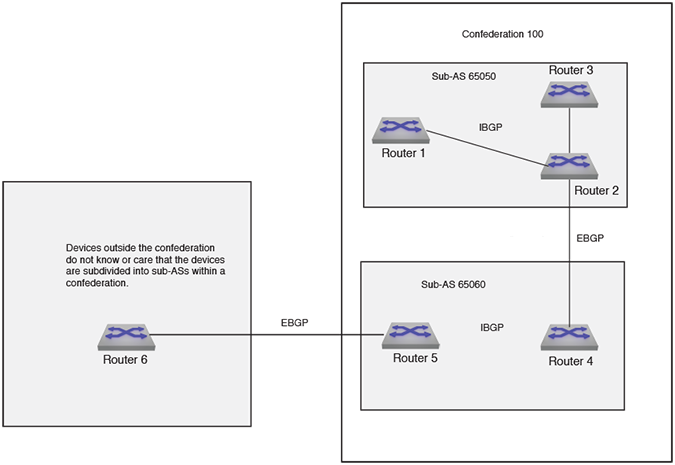
The neighbors from other autonomous systems within the confederation are treated as special eBGP peers when using the bgp confederation peers command.
switch(config)# router bgp 65050
switch(config-router-bgp)# bgp confederation identifier 100
switch(config-router-bgp)# bgp confederation peers 65060
switch(config-router-bgp)#
switch(config)# router bgp 65050
switch(config-router-bgp)# bgp confederation identifier 100
switch(config-router-bgp)# bgp confederation peers 65060
switch(config-router-bgp)# no bgp confederation peers 65032, 65036
switch(config-router-bgp)#
Enable the BGP FlowSpec address family on a per-peer basis using the following commands:
Example
switch(config)# router bgp id
switch(config-router-bgp)# address-family flow-spec [ipv4 | ipv6]
switch(config-router-bgp-af)# neighbor address activateUse the following command to explicitly enable BGP FlowSpec on an interface:
Example
switch(config)# interface Ethernet1
switch(config-if-Et1)# flow-spec ipv4 ipv6
Currently, both IPv4 and IPv6 must be enabled together on the interface. A user-defined TCAM profile, a feature introduced in EOS Relaease 4.20.5F, must be configured for TCAM support for BGP FlowSpec.
The ACL counters and BGP FlowSpec counters cannot be enabled simultaneously. To enable reporting of counters for BGP FlowSpec rules, use the following configuration:
Example
switch(config)# no hardware counter feature acl in
switch(config)# hardware counter feature flow-spec in
EOS supports BGP FlowSpec counter telemetry, and BGP updates the BGP FlowSpec counters periodically for a configured specific interval. Configure a range from 30 to 300 seconds.
To add BGP FlowSpec telemetry with an interval of 60 seconds, add the following parameter to the BGP configuration:
switch(config-router-bgp-af)# flow-spec counters poll interval 60 seconds
Enable BGP Flowspec on Layer 2 interfaces using the following commands:
switch(config)# flow-spec
switch(config-flow-spec)# hardware persistent
switch(config-flow-spec)# exit
switch(config)# interface eth1.1
switch(config-if-Eth1.1)# flow-spec ipv4
Configure FlowSpec for IPv4 or IPv6 on a L2 interface. Also, configure the TCAM profile to include the packet type, packet ipv4 forwarding bridged and packet ipv6 forwarding bridged.
Longest Prefix Match (LPM) uses an algorithm to determine the most specific route for a destination IP address. When a packet arrives, EOS checks the forwarding table (FIB) for matching network prefixes and then routes the packet to the destination VRF.
When enabled, the BGP Flowspec rules with VRF redirection programs the TCAM resource used by the VRF Selection Policy (VSP) while other BGP Flowspec rules continue to program into the BGP Flowspec TCAM. Packets traverse both TCAMs and a packet matches even if the matching criteria overlaps the other. For example, the following occurs on the switch when 2 rules have a BGP Flowspec configuration:
10.0.0.0/24, action vrf redirect, programs into the VSP TCAM.10.0.0.0/16, action drop, programs into the flowspec TCAM.If a packet arrives with source IP 10.0.0.1, the packet matches the rule in the VSP TCAM and performs FIB route lookup on the new VRF. Later in the pipeline, the packet matches the BGP Flowspec TCAM which drops the packet.
Use the following commands to add LPM redirect for IPv4 addresses to the BGP Flowspec configuration:
switch(config)# router bgp 201
switch(config-router-bgp)# address-family flow-spec ipv4
switch(config-router-bgp-af-flow-spec)# route-target redirect vrf lpmThe BGP show commands have been enhanced to display the flow-spec content for both IPv4 and IPv6 address families:
Example
The show bgp flow-spec ipv4 summary command displays the count of flowspec rules received from each peer:
switch(config)# show bgp flow-spec ipv4 summary
BGP summary information for VRF default
Router identifier 0.0.0.1, local AS number 10
Neighbor Status Codes: m - Under maintenance
Neighbor V AS MsgRcvd MsgSent InQ OutQ Up/Down State RulesRcd RulesAcc
10.0.0.2 4 10 12 4 0 0 00:02:18 Estab 2 2
10.0.1.2 4 10 6 4 0 0 00:02:18 Estab 0 0
The show bgp flow-spec ipv4 displays a brief description of each flowspec rule, including the matching rule and actions. The matching rule uses a format:
dest prefix; src prefix; [component:condition] +
The component is abbreviated, for example, DP for destination port and IP for IP Protocol as shown in the following example. The detail of the show command will display the full component name.
The condition is expressed with logical operators. In the following example, IP:=6|=17 matches any packets whose IP Protocol is 6 (TCP) or 17 (UDP). DP:>1010&<1024 matches any packets whose destination port is greater than 1010 and less than 1024.
Example
switch(config)# show bgp flow-spec ipv4
BGP Flow Specification rules for VRF default
Router identifier 0.0.0.1, local AS number 10
Rule status codes: # - not installed, M - received from multiple peers
Matching Rule Actions
10.2.3.0/24;*; Drop
10.2.4.0/24;10.2.0.0/16;IP:=6|=17;DP:>1010&<1024; Drop
The show bgp flow-spec detail displays the full details of each flowspec rule including the peer(s) it was received from, BGP properties, and an expanded description of the matching rule:
Example
switch(config)# show bgp flow-spec ipv4 detail
BGP Flow Specification rules for VRF default
Router identifier 0.0.0.1, local AS number 10
BGP Flow Specification Matching Rule for 10.2.3.0/24;*;
Rule identifier: 3882065752
Matching Rule:
Destination Prefix: 10.2.3.0/24
Source Prefix: *
Paths: 1 available
Local
from 10.0.0.2 (10.1.1.2)
Origin IGP, metric -, localpref 100, weight 0, valid, internal, best
Actions: Drop
BGP Flow Specification Matching Rule for 10.2.4.0/24;10.2.0.0/16;IP:=6|=17;DP:>1010&<1024;
Rule identifier: 3882090640
Matching Rule:
Destination Prefix: 10.2.4.0/24
Source Prefix: 10.2.0.0/16
IP Protocol: =6 | =17
Destination Port: >1010 & <1024
Paths: 1 available
Local
from 10.0.0.2 (10.1.1.2)
Origin IGP, metric -, localpref 100, weight 0, valid, internal, best
Actions: Drop
The show flow-spec ipv4 summary command displays an overall status of how many flowspec rules were received and how many were installed:
Example
switch(config)# show flow-spec ipv4 summary
Flow specification rules summary for VRF default
Total number of rules: 2
Number of installed rules: 2
The show flow-spec ipv4 displays the installation status of the rule, and a counter of how many hits it has accumulated. This command also compiles the received flowspec rules into rules that can be programmed into the TCAM. For example, logical expressions on values such as the destination port are converted to ranges, as shown below:
Example
switch(config)# show flow-spec ipv4
Flow specification rules for VRF default
Applied on: Ethernet47/1
Flow-spec rule: 10.2.3.0/24;*;
Rule identifier: 3882065752
Matches:
Destination prefix: 10.2.3.0/24
Actions:
Police: 80 Mbps (10 MBps)
Redirect: VRF customer1
Route via LDP tunnel index 4, MPLS label 100123
Route via LDP tunnel index 1, MPLS label 116507
Status:
Installed: yes
Counter: 312 packets
Flow-spec rule: 10.2.4.0/24;10.2.0.0/16;IP:=6|=17;DP:>1010&<1024;
Rule identifier: 3882090640
Matches:
Destination prefix: 10.2.4.0/24
Source prefix: 10.2.0.0/16
Next protocol: 17
6
Destination port: 1011-1023
Actions:
Police: 80 Mbps (10 MBps)
Redirect: VRF customer1
Route via LDP tunnel index 4, MPLS label 100123
Route via LDP tunnel index 1, MPLS label 116507
Status:
Installed: yes
Counter: 0 packets
For redirect actions, additional information is displayed to show how it was resolved.
Example
Actions:
Redirect: VRF customer1
Route via LDP tunnel index 4, MPLS label 100123
Route via LDP tunnel index 1, MPLS label 116507
The specified nexthop in the flow-spec redirect action can be resolved by the respective VRFs IP RIB over MPLS or GRE tunnel, as shown in the following example:
Example
Actions:
Redirect: VRF default, fc00:91:91:91::91
Route via Static Interface tunnel index 1
BGP Flowspec leverages BGP extended communities to disseminate and apply traffic filtering rules across a network. As part of this protocol, Interface-Set Extended Community configures a specific type of BGP Extended Community included with the Flowspec rules. BGP Flowspec rules can specify to apply only to traffic ingressing or egressing a specific set of interfaces, rather than applying the rule to all interfaces on the switch.
The Interface-Set Extended Community provides a mechanism to convey a specific set of interfaces to apply a rule. This may be useful in network environments where a Flowspec action, such as discarding DDoS traffic, must be localized to specific ingress points without affecting other traffic paths.
Selectiviely apply BGP Flowspec rules to sets of forwarding interfaces sharing a common group identifier. Configure the maximum number of supported interfaces using the following commands:
switch(config)# flow-spec
switch(config-flow-spec)# interface-set count limit limit
By default, the interface-set limit equals 0. Setting the interface-set limit to zero disables the feature, and does not program the interface-set rules. In this case, EOS only programs the VRF rules. EOS supports the following values for the count limit:
| Interface-Set Count Limit (Valid Values) | Minimum Port Qualifier Size Required (One VRF) |
|---|---|
| 3 | 3 |
| 7 | 4 |
| 15 | 5 |
| 31 | 6 |
| 63 | 7 |
| 127 | 8 |
| 255 | 9 |
| 511 | 10 |
| 1023 | 11 |
| 2047 | 12 |
To configure the limit successfully, configure the TCAM profile and set the port qualifier size number bits to a minimum size. Use the following commands to set the TCAM profile, bgp-comm, to use a minimum of 5 banks, ipv4 packets, port qualifier size 4:
switch(config)# hardware tcam
switch(config-tcam)# profile bgp-comm
switch(config-tcam-profile-bgp-comm)# feature flow-spec port ipv4
switch(config-tcam-feature-flow-spec-port-ipv4)# port qualifier 4The configuration limits the interface-set count limit to 7 and if the configuration does not meet the criteria for port qualifier size, the configuration sets the count limit to zero and only the VRF rules apply.
Use the following commands to configure the interface-set assignment to 7 on Ethernet1:
switch(config)# interface Ethernet1
switch(config-if-Eth1# interface-set 7The output of the show flow-spec command displays a section with interface-sets information:
switch# show flow-spec
Actions:
Police: 80 Mbps (10 Mbps)
Interface sets: 1
Applied on: Ethernet1/1match community or-results COMMLIST1 COMMLIST2
match extcommunity or-results EXTCOMMLIST1 EXTCOMMLIST2
match large-community or-results LARGECOMMLIST1 LARGECOMMLIST2
switch(config)# service routing protocols model multi-agent
switch(config)# ip community-list COMMLIST1 permit 1:1
switch(config)# ip community-list COMMLIST2 permit 2:2
switch(config)# route-map IN-POLICY
switch(config-route-map-IN-POLICY)#match community or-results
COMMLIST1 COMMLIST2
switch# show route-map IN-POLICY
route-map IN-POLICY permit 10
Description:
Match clauses:
match community or-results COMMLIST1 COMMLIST2
SubRouteMap:
Set clauses:
set local-preference 500
route-map IN-POLICY permit 20
Description:
Match clauses:
SubRouteMap:
Set clauses:
switch# show run | in 200.200.200.57
neighbor 200.200.200.57 remote-as 300
neighbor 200.200.200.57 update-source Loopback200
neighbor 200.200.200.57 ebgp-multihop
neighbor 200.200.200.57 route-map IN-POLICY in
neighbor 200.200.200.57 maximum-routes 0
switch# show ip bgp community 1:1
BGP routing table information for VRF default
Router identifier 220.220.220.51, local AS number 200
Route status codes: s - suppressed, * - valid, > - active, # - not installed, E - ECMP head, e - ECMP
S - Stale, c - Contributing to ECMP, b - backup, L - labeled-unicast
% - Pending BGP convergence
Origin codes: i - IGP, e - EGP, ? - incomplete
AS Path Attributes: Or-ID - Originator ID, C-LST - Cluster List, LL Nexthop - Link Local Nexthop
Network Next Hop Metric LocPref Weight Path
* > 66.170.224.0/20 200.200.200.57 0 500 0 300 ?
* > 66.170.232.0/21 200.200.200.57 0 500 0 300 ?
* > 128.29.0.0/16 200.200.200.57 0 500 0 300 ?
switch# show ip bgp community 2:2
BGP routing table information for VRF default
Router identifier 220.220.220.51, local AS number 200
Route status codes: s - suppressed, * - valid, > - active, # - not installed, E - ECMP head, e - ECMP
S - Stale, c - Contributing to ECMP, b - backup, L - labeled-unicast
% - Pending BGP convergence
Origin codes: i - IGP, e - EGP, ? - incomplete
AS Path Attributes: Or-ID - Originator ID, C-LST - Cluster List, LL Nexthop - Link Local Nexthop
Network Next Hop Metric LocPref Weight Path
* > 192.12.24.0/24 200.200.200.57 0 500 0 300 ?
* > 192.47.242.0/24 200.200.200.57 0 500 0 300 ?
To set the default policy behavior for BGP so that all routes can be denied or rejected, use the bgp missing policy command. Options control inbound and outbound directions independently. When the inbound direction is affected, currently installed routes from the peer are removed (and withdrawn from other attached peers). When the outbound direction is affected, currently exported routes to the peer are withdrawn. Setting the Missing Policy Action options back to its default/permit value re-applies the current inbound route-map policy processing to the set of routes received from the peer and export routes according to the configured outbound route-map. If soft-reconfiguration is disabled and the inbound direction is affected then the peer must re-send its routes (e.g. a manual “clear ip bgp” command is required).
Permit is the default missing policy action when no/default are applied. Entering the ‘default’ form of the command in a non-default VRF will cause the non-default VRF to inherit the setting from the default VRF. Entering the no form of the command in a non-default VRF will cause the non-default VRF to be configured with the permit setting regardless of the default VRF setting.
The include keyword is optional, and only takes effect in the multi-agent protocol model.
switch(config-router-bgp)# bgp missing-policy [include {prefix-list|sub-route-map}]
direction [in|out] action [permit|deny|deny-in-out]
switch(config-router-bgp)# [no|default] bgp missing-policy [include {prefix-list|sub-route-map}]
direction [in|out] action
For the actions, the permit and deny options inherit the direction of route denial from the direction, while the deny-in-out option specifically calls out denying routes in both directions.
The include keyword specifies that the policy constructs in the route map should also be examined. The options to the include keyword are.
switch(config-router-bgp)# show ip bgp neighbors
BGP neighbor is 1.0.0.2, remote AS 200, external link
BGP version 4, remote router ID 0.0.1.1, VRF default
Negotiated BGP version 4
…Missing policy/default deny import action is active
Missing policy/default deny export action is active
Inbound route map is rm1
Outbound route map is rm2
…
Apply an optional delay before processing inbound update messages from peers, and may be useful when routes from a peer depend on routes from another. The routes from the second peer must install before the routes from the first peer process, and applying the delay to the first peer allows the second peer to install the routes first. Configure the delay per peer and apply it to all address families negotiating with the peer. The delay timer starts when the peer becomes established, and routes from the peers with the delay process only after the time expires. EOS supports this feature on default and non-default VRFs on the network. The inbound delay does not apply to switch reloads or BGP agent restarts.
Configure the delay per peer and apply it to all address families negotiating with the peer. The delay timer starts when the peer becomes established, and routes from the peers with the delay process only after the time expires. EOS supports this feature on default and non-default VRFs on the network.
The inbound delay does not apply to switch reloads or BGP agent restarts.
Example
switch(config)#router bgp
switch(config-router-bgp)#neighbor peer mybgp-peers rib-in delay 30 event peer-init
To configure BGP to translate IPv4-mapped IPv6 addresses to IPv4 addresses when receiving next hops in labeled-unicast routes, use the neighbor next-hop resolution v4-mapped-v6 translation command. With this configuration, when the switch receives an IPv4-mapped IPv6 address for the next hop of an IPv6 labeled-unicast route, it will translate it to an IPv4 address, which allows the next hop to be resolved in an IPv4 network. This command takes effect only if the multi-agent routing protocol model is running. It applies only to the default VRF.
Example
switch(config)# router bgp 64510
switch(config-router-bgp)# address-family ipv6 labeled-unicast
switch(config-router-bgp-af-label)# neighbor v6_pg next-hop resolution v4-mapped-v6 translation
switch(config-router-bgp-af-label)#
A BGP router advertising a route can provide the IPv4-mapped IPv6 address of one of its local interfaces, such as a loopback interface, as the next hop. This source interface is specified with the neighbor next-hop-self command. The interface must be configured with an IPv4 address for this to be effective.
This configuration does not enable next-hop-self. It simply specifies the interface to be provided if the router advertises itself as the next hop. The next-hop-self action can be enabled with the neighbor next-hop-self command, or by configuring Egress Peer Engineering (EPE) using the neighbor default-originate command, or by other methods.
Example
switch(config)# router bgp 64510
switch(config-router-bgp)# neighbor 2001:0db8::1 next-hop-self
switch(config-router-bgp)# neighbor 2001:0db8::1 next-hop-self v4-mapped-v6 source-interface Loopback 0
switch(config-router-bgp)#
For BGP EVPN VXLAN fabrics, automatic route distinguisher (RD) generation simplifies the network configuration by automatically generating unique RD values based on the BGP Router ID and the VRF ID, eliminating manual RD configuration. EOS supports this configuration for the following address families:
According to RFC4364, a route distinguisher (RD) consists of two fields, type and value. In the type field, the RFC defines three values: 0, 1, and 2 that use the following encoding types:
(<asn><nn>)(<ip-addr><nn>)(<asn4><nn>)Autogeneration of RDs generates a Type 1 RD by using the router ID as the 4-byte administrator subfield and a 2-byte assigned number subfield from a configurable range.
Configure the automatic RD in the BGP Router Configuration Mode using a range for the RD and the address family type:
switch(config)#router bgp asn
switch(config-router-bgp)#route-distinguisher
switch(config-route-distinguisher)#assignment auto range start_range end_range
?switch(config-route-distinguisher)#assignment auto address-family l2-evpnEOS disables this feature by default. All address families within the L2 EVPN configuration share the same range.
Peer Tagging and Route Filtering allows or discards BGP route advertisements from peers with received routes. Assign a peer tag to a peer or peer group for inbound traffic and discard or allow route advertisements by the peer tag in the outbound direction. Use this feature to discard AS loop routes in the outbound direction in data center deployments.
Configure the peer tag at both the instance, router-bgp, and address-family levels, router-bgp-af.
BGP can detect and prevent Autonomous Systems (AS) loop detection for the inbound direction as well as discard AS loop routes in the outbound direction to optimize network performance. In the example topology, the leaf and spine switches have been configured as EBGP peers and the spine switches configured with the same AS number. Leaf1 receives BGP routes from Spine1 and re-advertises them to Spine2 and Spine3 because of the EBGP peering configuration. Inbound AS loop detection drops the routes on Spine2 and Spine 3 which consumes a significant amount of CPU processing and memory.
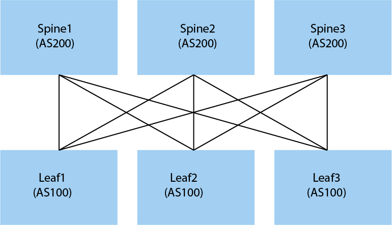
Use the following configuration on Leaf1 to prevent Leaf1 from advertising routes received from any Spine back to other Spines. The Spine switches use a peer-group named, SPINES, and a peer-tag called, spine-routes, applied to both inbound and outbound directions of the peer-group, Spines. Routes received from each Spine have a tag, spine-routes, and discarded in route advertisements to the other two Spines.
switch(config)# router bgp 100
switch(config-router-bgp)# neighbor SPINES remote-as 200
switch(config-router-bgp)# neighbor SPINES peer-tag in spine-routes
switch(config-router-bgp)# neighbor SPINES peer-tag out discard spine-routes
switch(config-router-bgp)# neighbor 10.1.1.1 peer group SPINES
switch(config-router-bgp)# neighbor 10.1.2.1 peer group SPINES
switch(config-router-bgp)# neighbor 10.1.3.1 peer group SPINESswitch(config-router-bgp)# address-family ipv4
switch(config-router-bgp-af)# neighbor 10.1.1.1 peer-tag in spine-routes
switch(config-router-bgp-af)# neighbor 10.1.1.1 peer-tag out discard spine-routesIn addition to AS loop detection, use the feature for scenarios that require discarding route advertisements based on the receiving peers. The following example configures a router to accept route advertisements from 1.1.1.1 only if tagged with bgp-lab in the inbound direction. Otherwise, the router rejects the route advertisements.
switch(config)# router bgp 100
switch(config-router-bgp)# neighbor 10.1.1.1 peer-tag out allow bgp-labUse the following show commands to display peer-tag information:
switch# show ip bgp neighbors 10.1.1.1
BGP neighbor is 10.0.0.1, remote AS 100, external link
BGP version 4, remote router ID 10.0.1.1, VRF default
…
BGP session driven failover for IPv4 Unicast is disabled
BGP session driven failover for IPv6 Unicast is disabled
IPv4 Unicast inbound peer-tag: spine-routes
IPv4 Unicast deny outbound peer-tag: spine-routes
IPv6 Unicast inbound peer-tag: spine-routes
IPv6 Unicast Permit outbound peer-tag: spine-routes
Message Statistics:Use the show bgp update-group command to display the peer-tag configured on the outbound route of an update group with the number of routes matched and dropped by the peer-tag:
switch# show bgp update-group
BGP update groups information for VRF default
BGP version 4 update group 5, external
Policy group ID is 10
Send IPv6 Unicast updates
State of attributes of the reflected routes not preserved
Extended next hop capability is disabled
Private AS number to be removed from updates
Neighbor AS number is 645501
Configured local AS number is 200
Four-byte ASN negotiated
Missing policy action is permit
Deny outbound peer-tag is spine-routes
Advertisement routes: 0
Queued advertisements: 0
Policy Statistics
Path Drop Reason Drop Count
Policy rejects 0
NO_EXPORT / NO_ADVERTISE community 0
Extended next hop mismatch 0
Received link-local next hop 0
Next hop self no local label 0
Outbound peer-tag rejects 100
Has 1 members, 1 member(s) in sync (* indicates member is in sync)
Neighbor InSync
10.1.1.1 *
10.1.2.1 *
10.1.3.1Use the same command to display information when the outbound peer-tag has an allow action:
switch# show bgp update-group
BGP update groups information for VRF default
BGP version 4 update group 5, external
Policy group ID is 10
Send IPv6 Unicast updates
State of attributes of the reflected routes not preserved
Extended next hop capability is disabled
Private AS number to be removed from updates
Neighbor AS number is 645501
Configured local AS number is 200
Four-byte ASN negotiated
Missing policy action is permit
Permit outbound peer-tag is spine-routes
Advertisement routes: 0
Queued advertisements: 0
Policy Statistics
Path Drop Reason Drop Count
Policy rejects 0
NO_EXPORT / NO_ADVERTISE community 0
Extended next hop mismatch 0
Received link-local next hop 0
Next hop self no local label 0
Outbound peer-tag rejects 0
Has 1 members, 1 member(s) in sync (* indicates member is in sync)
Neighbor InSync
10.1.1.1 *
10.1.2.1 *
10.1.3.1 In Arista EOS, the BGP Aggregate Address Minimum Contributors feature provides a safety mechanism for route summarization. It prevents a partial network from attracting traffic it cannot actually reach, a scenario commonly referred to as traffic blackholing.
EOS does not generate an aggregate route unless the BGP table has a specific number of active component subnets. If the number of active subnets falls below the configured minimum threshold, the switch withdraws the aggregate route. Traffic shifts to the redundant peer with a healthy number of contributor routes.
switch(config)# router bgp BGP-24
switch(config-router-bgp)# aggregate-address 172.16.21.35/32 minimum-contributors 10
switch(config-router-bgp)#Configure the number of minimum contributors from 1 to 65535 with the default value of 1.
Enable BGP Monitoring Protocol (BMP) in the Router BGP Configuration Mode.
Use the following commands to export BGP paths on the BGP router, 64512, router ID, 1.0.0.1, and VRF purple for BMP:
switch(config)# router bgp 64512
switch(config-router-bgp)# router-id 1.0.0.1
switch(config-router-bgp)# bgp monitoring
switch(config-router-bgp)# vrf purple
switch(config-router-bgp-vrf-purple)# rd 530:12
The bgp monitoring command enables the export of BGP received paths and Loc-Rib routes on non-default VRFs. BMP only supports non-default VRFs with a route distinguisher (RD) configured in the BGP Router VRF Configuration Mode. The RD distinguishes peers with the same IP address but in different VRFs.
If the RD or router ID changes later, BMP sends Peer Down messages with the old RD value to all BGP peers in the VRF, and then sends Peer Up and Route Monitoring messages with the new RD value.
Use the following commands to disable BMP on router 64512 with the router ID 1.0.1.1:
switch(config)# router bgp 64512
switch(config-router-bgp)# no neighbor 1.0.1.1 monitoringWith BMP and export for an address family (AFI/SAFI) enabled, the BGP router exports Adj-RIB-In information for all VRFs. Filter the VRFs exported by the BGP router using the following commands:
switch(config)# router bgp 64512
switch(config-router-bgp)# vrf mgmt
switch(config-router-bgp-vrf-mgmt)# bgp received routes monitoring disabledThis prevents the BGP router from exporting the routes on VRF. Using the no or default version of the command reverts the configuration to the default behavior of exporting the Adj-RIB-Ins information.
Use the monitoring timestamp to set the timestamp in BMP Route Monitoring messages to zero (none) or to the Route Monitoring Message construction time. BMP uses the send-time as the default value.
To configure the timestamp to none, use the following commands:
switch(config)# router bgp 64512
switch(config-router-bgp)# monitoring timestamp noneBy default, the pre-policy and the post-policy routes advertise to the monitoring station. Use the no monitoring received routes command disables either pre-policy or post-policy routes or both. Use the following commands to disable pre-policy routes:
switch(config)# router bgp 64512
switch(config-router-bgp)# no monitoring received routes pre-policyTo enable exporting pre-policy and post-policy routes, use the following commands:
switch(config)# router bgp 64512
switch(config-router-bgp)# monitoring received routes pre-policy post-policyThe following table lists the supported statistics counters for BMP:
| Statistic Type | Description |
|---|---|
| 0 | Number of prefixes rejected by the inbound policy |
| 7 | Number of routes in Adj-RIBs-In |
| 9 | Number of routes in each AFI/SAFI Adj-RIB-In |
BMP disables statistics reporting by default. Use the following commands to turn on statistics reporting for a Monitoring Station:
switch(config)# router bgp 64512
switch(config-router-bgp)# monitoring station S1
switch(config-router-bgp-monitoring-station-S1)# statisticsOnce enabled on a monitoring station, the station begins receiving periodic SR announcements containing the supported statistics. The SR announcements generate periodically, every 30 seconds by default, whether or not any changes occur to the statistics. Configure the statistics reporting interval to 45 seconds using the following commands:
switch(config)# router bgp 64512
switch(config-router-bgp)# monitoring statistics interval 45BMP supports exporting BGP received paths with a specific address family and exports IPv4 Unicast and IPv6 Unicast Adj-RIB-In paths by default. Enable or disable exporting BGP received paths with a specific address family. Use the following commands to specify IPv4 Unicast Adj-RIB-In paths:
switch(config)# router bgp 64512
switch(config-router-bgp)# monitoring received routes address-family ipv4 unicastTo export BGP received paths, configure a BMP Monitoring Station using the monitoring station station_name command. Specify a connection mode, the IP address of the station, and depending on the connection mode, the local or remote TCP port to establish a TCP connection to the station. Use one of the following connection modes:
switch(config)# router bgp 64512
switch(config-router-bgp)# monitoring port 5001For passive mode connections, configure an IP address for the BMP Monitoring Station:
switch(config)# router bgp 64512
switch#(config-router-bgp)# monitoring station S1
switch#(config-router-bgp-monitoring-station-S1)# connection mode passive
switch#(config-router-bgp-monitoring-station-S1)# connection address 192.168.1.5The connection address must match the source IP address used by the monitoring station to connect to the router. Since the monitoring stations does not send messages to the router, the IP address provides the only way to identify the station and match the correct configuration.
For active mode connections, configure the monitoring station IP address and port number:
switch(config)# router bgp 64512
switch(config-router-bgp)# monitoring station S1
switch(config-router-bgp-monitoring-station-S1)# connection mode active port 5000
switch(config-router-bgp-monitoring-station-S1)# connection address 192.168.1.5The monitoring station must listen for connections at the specified IP address and TCP port number.
Use the following commands to configure a monitoring station, Stn-2, on a VRF, mgmt:
switch(config)# router bgp 64512
switch(config-router-bgp)# monitoring station Stn-2
switch(config-router-bgp-monitoring-station-S1)# connection address 192.168.1.5 vrf mgmtThe description parameter allows the addition of descriptive text for the monitoring station and displays that information in BMP station show commands.
Use the following commands to add a description, monitoring remote network, to the monitoring station, Stn-2:
switch(config)# router bgp 64512
switch(config-router-bgp)# monitoring station Stn-2
switch(config-router-bgp-monitoring-station-S1)# description monitoring remote networkUse the following commands to configure export policy filtering at the station level:
switch(config)# router bgp 64512
switch(config-router-bgp)# monitoring station Stn-2
switch(config-router-bgp-monitoring-station-S1)# no export-policy received routes pre-policy
switch(config-router-bgp-monitoring-station-S1)# no export-policy received routes post-policyUse the shutdown command to shut down TCP sessions to the monitoring station. The router stops initiating TCP connections to stations configured with an active mode connection. For stations configured with a passive mode connection, the router stops accepting TCP sessions from the station.
switch(config)# router bgp 64512
switch(config-router-bgp)# monitoring station Stn-2
switch(config-router-bgp-monitoring-station-S1)# shutdownUse the update-source command to select the source IP address sent by the router for the TCP session. The monitoring station must be able to reach the IP address. Use the following commands to update the source IP address to interface, ethernet1/1:
switch(config)# router bgp 64512
switch(config-router-bgp)# monitoring station Stn-2
switch(config-router-bgp-monitoring-station-S1)# update-source interface ethernet1/1The connection keepalive command periodically checks the health of the TCP connection with the station. Since the router does not receive messages from the station, the router cannot detect when the station becomes unavailable due to power or link failure. Using a TCP keepalive probe allows the router to quickly detect the loss of a station connection. Configure a keepalive probe with 30 seconds of idletime, 30 seconds between TCP keepalive probes, and sending 100 probes before closing the connection:
switch(config)# router bgp 64512
switch(config-router-bgp)# monitoring station Stn-2
switch(config-router-bgp-monitoring-station-S1)# connection keepalive 30 30 100For additional security, enable the TCP MD5 signature option for the TCP session with the station. The same key must be configured on the router and the BMP station. The authentication-key command enables this option and configures the key used on the session. Use the following commands to configure a password, mySecretID, for TCP sessions:
switch(config)# router bgp 64512
switch(config-router-bgp)# monitoring station Stn-2
switch(config-router-bgp-monitoring-station-S1)# authentication mySecretIDUse the following configuration for a BMP station (S1) to receive additional-paths advertisements, for example, NLRIs containing addpath-ids. If any BGP peer has a configuration for additional-paths and can send addpath-id values with the required additional-paths visibility for that peer.
switch(config)# router bgp 64512
switch(config-router-bgp)# monitoring station S1
switch(config-router-bgp-monitoring-station-S1)# export-policy received routes additional-pathsBy default, BMP disables exporting Local RIB for all monitoring stations on all VRFs. Enable exporting the Local RIB per station or per VRF. You must configure the router ID for BGP and the RD for a non-default VRF. BMP exports IPv4 and IPv6 Unicast routes into the Local RIB including imported VPN routes. The following commands configure exporting of the Local RIB to a single station:
switch(config)# router bgp 64512
switch(config-router-bgp)# monitoring station S1
switch(config-router-bgp-monitoring-station-S1)# export-policy bgp rib bestpathsTo configure exporting of Local RIB to all monitoring stations, use the following commands:
switch(config)# router bgp 64512
switch(config-router-bgp)# monitoring bgp rib bestpathsPer monitoring station configuration overrides the global BGP configuration.
Use the following commands to enable the export of a specific BGP VRF, Blue, Local RIB:
switch(config)# router bgp 64512
switch(config-router-bgp)# vrf Blue
switch(config-router-bgp-vrf-Blue)# bgp rib bestpaths monitoringPer VRF configuration overrides the global VRF configuration.
Use the show bgp monitoring command to display information about the BMP status on the switch:
switch# show bgp monitoring
BGP Monitoring status: enabled
BMP Timestamp mode: send-time
BMP Export policies: pre-policy, post-policy
VRFs filtered: vrf1, vrf2
Station - bmp_A
Connection mode: active
VRF: default
Address: 192.0.2.1
Port: 5000
Connection: connected
State: up
Uptime: 00:09:17
Station flap count: 0
The show bgp monitoring summary command displays a summary of the station names, status, and duration of activity:
switch# show bgp monitoring summary
BGP Monitoring status: enabled
Station NameStatus Uptime
---------------- ------------ ------------
bmp_A connecting -
bmp_B idle -
bmp_C up 00:11:46The show bgp monitoring station station_name displays details about per-station configurations. Use the command to display information about station bmp_B:
switch# show bgp monitoring station bmp_B
Station - bmp_B
Station export policies: pre-policy, post-policy
Connection mode: unknown
VRF: default
Connection: disconnected
State: idle
Station flap count: 0The show bgp monitoring active command displays information about stations receiving TCP connection requests from a BGP router:
switch# show bgp monitoring active
Active Station - bmp_C
VRF: default
Address: 192.0.2.1
Port: 5000
Retry interval: 30s
Connection: connected
Attempts: 4484
Successes: 1
Errors: 5The show bgp monitoring passive command displays information about stations that the router listens for TCP connections:
switch# show bgp monitoring passive
IPv4 Passive Listener VRF - default
Port 5000
Status: Listening
Stations:
bmp_A: (198.51.100.100)
bmp_B: (192.0.2.5)
Accepted: 2
Rejected: 5
IPv6 Passive Listener VRF - default
Port 5000
Status: Disabled
Reason:
Stations:
bmp_A: (2001:DB8::800:1)
bmp_B: (2001:DB8::900:2)
Accepted: 4
Rejected: 0The show bgp monitoring station station_name detail command displays TCP statistics for a BMP monitoring station:
switch# show bgp monitoring station bmp_C detail
Station - bmp_C
Connection mode: active
VRF: default
Address: 192.0.2.1
Port: 5000
Connection: connected
State: up
Uptime: 00:13:06
Station flap count: 1
TCP Socket Information:
TCP state is ESTABLISHED
Send-Q: 0/200
Outgoing Maximum Segment Size (MSS): 1448
Total Number of TCP retransmissions: 0
Options:
Timestamps enabled: yes
Selective Acknowledgments enabled: yes
Window Scale enabled: yes
Explicit Congestion Notification (ECN) enabled: no
Socket Statistics:
Window Scale (wscale): 9,9
Retransmission Timeout (rto): 204.0ms
Round-trip Time (rtt/rtvar): 0.1ms/0.1ms
Delayed Ack Timeout (ato): 0.0ms
Congestion Window (cwnd): 10
TCP Throughput: 864.48 Mbps
Advertised Recv Window (rcv_space): 29200The shutdown (BGP) command disables BGP operations without disrupting the BGP configuration. The router bgp command disables BGP and removes the BGP configuration.
The shutdown (BGP) command resumes BGP activity.
switch(config-router-bgp)# shutdown
switch(config-router-bgp)#
switch(config-router-bgp)# no shutdown
switch(config-router-bgp)#
When entered without parameters, the clear ip bgp command clears all BGP learned routes from the routing table, reads routes from designated peers, and sends routes required by those peers. Routes that are read or sent are processed through any modified route map or AS-path access list.
Followed by an asterisk (*), it clears the BGP sessions with all BGP peers. To reset the session with a specific peer, enter the peer’s IP address at the end of the command.
Example
switch# clear ip bgp
! Peerings for all neighbors were hard reset
switch#
BGP IPv6 Link Local Peers Discovery supports a dynamic configuration model to eliminate the need for the network administrator to assign and configure IPv6 addresses for BGP peering.
BGP IPv6 Link Local Peers Discovery uses IPv6 router advertisement to discover the peers IPv6 link local address. Devices must have IPv6 routing enabled, and the interface used for peering must have an IPv6 link local address. The time taken to discover the peers IPv6 link local address is proportional to the time taken by the peer to send a router advertisement message. When bringing up BGP sessions based on router advertisements received, a flurry of router advertisements on the interfaces causes the Rib agent to do more work and potentially delays the discovery of BGP neighbors over those interfaces and the establishment of BGP sessions. Since these are link local addresses, the peers must be directly connected at Layer 3.
These show commands are invaluable for debugging route map behavior. By providing a BGP-reachable prefix (from a BGP peer or redistribution source), you can evaluate a specified route map. If no route map is explicitly given, the system will use the route map applied to the peer. You can also select any configured route map, even if it's not currently applied. If no VRF is specified, the default VRF will be used. The output clearly details the evaluation of each sequence, including the results of match clauses, any sub-route map evaluations, applied set clauses, the impact of continue statements, and the final permit/deny outcome for the sequence. This comprehensive output enables users to gain a thorough understanding of how a route map processes specific paths.
show bgp debug policy inbound neighbor { <neighbor address> | all } ipv4 unicast [ vrf <vrf name> ] [ route-map <route-map> ] <prefix>
show bgp debug policy outbound neighbor <neighbor address> ipv4 unicast [ vrf <vrf name> ] [ route-map <route-map> ] <prefix>
show bgp debug policy redistribute ipv4 unicast [ vrf <vrf name> ] [ route-map <route-map> ] <prefix>
switch(config)# show bgp debug policy inbound neighbor 10.1.2.1 ipv4 unicast vrf red route-map foo 10.100.20.0/24
NLRI 10.100.20.0/24, received from 10.1.2.1
route-map foo
seq 10 permit
match as 1 (failed)
Seq result: fall through to next sequence
seq 20 permit
match as 1 (matched)
sub-route-map sub_foo (permit)
seq 10 permit
match as 1 (matched)
Seq result: permit
Route map result: permit, matching sequence 10
Seq result: permit
Route map result: permit, matching sequence 20This section shows example configurations and topologies for iBGP (BGP Example 1) and eBGP (BGP Example 2).
Example 1 features an internal BGP (iBGP) link that connects peers in AS 100.
Figure 7 - BGP Example 1 displays an iBGP connection, linking neighbors within AS 100. Each switch advertises two subnets. In UPDATE packets sent by Switch A, the LOCAL_PREF field is 150. In UPDATE packets sent by Switch B, the LOCAL_PREF field is 75.
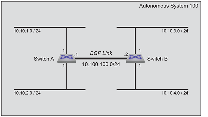
This code configures the Example 1 BGP instance on both switches.
Example 2 creates an external BGP (eBGP) link that connects routers in AS 100 and AS 200.
Figure 8 - BGP Example 2 displays an eBGP connection, linking Switch A in AS 100 to Switch B in AS 200. Each switch advertises two subnets.
Switch A assigns a local preference of 150 to networks advertised by Switch B. Switch B assigns a local preference of 75 to networks advertised by Switch A.
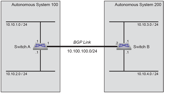
This code configures the Example 2 BGP instance on both switches.
The address-family command places the switch in address-family configuration mode to configure the address family setting of addresses configured as BGP neighbors. The address-family configuration mode is not a group change mode; running-config is changed immediately after commands are executed. The exit command does not affect the configuration.
The no address-family and default address-family commands delete the specified address family from running-config by removing all commands previously configured in the corresponding address-family mode.
The exit command returns the switch to router-BGP configuration mode.
Command Mode
Router-BGP Configuration
Command Syntax
bgp [ipv4 | ipv6]
no bgp [ipv4 | ipv6]
default bgp [ipv4 | ipv6]
Example
switch(config)# router bgp 1
switch(config-router-bgp)# address-family ipv6
switch(config-router-bgp-af)# neighbor 172.10.1.1 activate
switch(config-router-bgp-af)# exit
switch(config-router-bgp)#Use the address-family flow-spec command to filter or redirect DDoS traffic on edge routers. The no and default versions of the command removes the filter to redirect the DDoS traffic.
Command Mode
BGP Router Configuration Mode
Command Syntax
address-family flow-spec [ipv4 | ipv6] route-target redirect vrf lpm
address-family flow-spec [ipv4 | ipv6] route-target redirect vrf lpm
address-family flow-spec [ipv4 | ipv6] route-target redirect vrf lpm
Example
The BGP Flowspec address family is enabled on a per-peer basis with:
switch(config)# router bgp id
switch(config-router-bgp)# address-family flow-spec [ipv4|ipv6]
switch(config-router-bgp-af)# neighbor address activateTo add LPM for a VRF, use the following commands:
switch(config)# router bgp 201
switch(config-router-bgp)# address-family flow-spec ipv4
switch(config-router-bgp-af-flow-spec)# route-target redirect vrf lpmThe address-family flow-spec neighbor command in the BGP Router Configuration Mode enables Flowspec on a BGP configuration to filter or redirect DDoS traffic on edge routers.
The [no | default] version of the command removes the configuration from the running-config.
Command Mode
BGP Router Configuration Mode
Command Syntax
address-family flow-spec [ipv4 | ipv6] neighbor ip_address [activate | send-community extended]
no address-family flow-spec [ipv4 | ipv6] neighbor ip_address [activate | send-community extended]
default address-family flow-spec [ipv4 | ipv6] neighbor ip_address [activate | send-community extended]
Parameters
Example
Use the following commands to activate a neighbor IPv4 address, 192.168.21.1, for the Flow Specification address family on BGP router 2500:
switch(config)# router bgp 2500
switch(config-router-bgp)# address-family flow-spec ipv4
switch(config-router-bgp-af-flow-spec)# neighbor 192.168.21.1 activate
switch(config-router-bgp-af-flow-spec)#
The aggregate-address command creates an aggregate route in the Border Gateway Protocol (BGP) database. Aggregate routes combine the characteristics of multiple routes into a single route that the switch advertises. Aggregation can reduce the amount of information that a BGP speaker is required to store and transmit when advertising routes to other BGP speakers. Aggregate routes are advertised only after they are redistributed.
The advertised address of the aggregate is entered as an IP subnet; any routes configured on the switch that lie within that subnet then become contributors to the aggregate. Note that on Arista switches the BGP aggregate route will become active if there are any available contributor routes on the switch, regardless of the originating protocol. This includes routes configured statically.
Command options affect the attributes associated with the aggregated route, the advertisement of the contributor routes that comprise the aggregate, and which contributor routes are included.
Command options affect the following aggregate routing attributes:
When the command includes as-set, the aggregate route’s AS_SET attribute contains the AS numbers of contributor routes. This can help BGP neighbors to prevent loops by rejecting aggregate routes that include their AS number in the AS_SET.
When the command does not include as-set, the aggregate route’s ATOMIC_AGGREGATE attribute is set and the aggregate route AS_PATH will include the longest leading PATH_SEQ of the AS_PATH which is common to all contributor routes. For example, for the aggregate 1.0.0.0/16 with two contributors present, the AS_PATH for the aggregate is 100 200 as shown.
Aggregate
1.0.0.0/16 as-path ??
Contributors
1.0.1.0/24 as-path 100 200 400 500
1.0.2.0/24 as-path 100 200 300
The no aggregate-address and default aggregate-address commands remove the corresponding aggregate-address command from running-config.
Command Mode
Router-BGP Configuration
Command Syntax
aggregate-address AGGREGATE_NET [AS_SET][SUMMARY][ATTRIBUTE_MAP][MATCH_MAP]
no aggregate-address AGGREGATE_NET
default aggregate-address AGGREGATE_NET
switch(config)# router bgp 1
switch(config-router-bgp)# aggregate-address 10.16.48.0/20 as-set
switch(config-router-bgp)# exit
switch(config)#
switch(config)# route-map map1 permit 10
switch(config-route-map-map1)# set community 45
switch(config-route-map-map1)# exit
switch(config)# router bgp 1
switch(config-router-bgp)# aggregate-address 10.16.48.0/20 attribute-map map1
switch(config-router-bgp)# exit
switch(config)#
switch(config)# route-map matchmap permit 10
switch(config-route-map-matchmap)# match ip address prefix-list agglist
switch(config-route-map-matchmap)# exit
switch(config)# router bgp 1
switch(config-router-bgp)# aggregate-address 1.1.0.0/16 match-map matchmap
switch(config-router-bgp)#The authentication-key command adds security to the TCP session to the BMP monitoring station. Configure the same key on the BGP router and the BMP monitoring station. Access this command in the Monitoring Station Configuration Mode.
Command Mode
Monitoring Station Configuration
Command Syntax
authentication-key key
Parameters
Example
switch(config)# router bgp 64512
switch(config-router-bgp)# monitoring bgp
switch(config-router-bgp)# monitoring station bmp_E
switch(config-router-bgp-monitoring-station-bmp_E)# authentication-key !ckCK!nfxH3!LsyBr3!By default, BGP will advertise only those routes that are active in the switch’s RIB. This can contribute to dropped traffic. If a preferred route is available through another protocol (like OSPF), the BGP route will become inactive and not be advertised; if the preferred route is lost, there is no available route to the affected peers. Advertising inactive BGP routes minimizes traffic loss by providing alternative routes.
The bgp advertise-inactive command configures BGP to advertise inactive routes to BGP neighbors. Inactive route advertisement is configured globally, but the global setting can be overridden on a per-VRF basis.
The no bgp advertise-inactive and default bgp advertise-inactive commands restore the default BGP behavior (advertising only active routes) by removing the corresponding bgp advertise-inactive command from running-config.
Command Mode
Router-BGP Configuration
Command Syntax
bgp advertise-inactive
no bgp advertise-inactive
default bgp advertise-inactive
Example
switch(config)# router bgp 64500
switch(config-router-bgp)# bgp advertise-inactive
switch(config-router-bgp)#The bgp always-compare-med command configures the switch to always consider Multi-Exit Discriminator (MED) values (also known as “metric”) in best-path selection. By default, this function is disabled, and MED values are compared only if two paths have the same neighbor AS.
When there are two or more links between autonomous systems, MED values may be set by a router in the originating AS to give preferences to certain routes. In comparing MED values, the lower value is preferred.
The no bgp always-compare-med and default bgp always-compare-med commands restore the default behavior of comparing MED values only on paths with the same neighbor AS.
Command Mode
Router-BGP Configuration
Command Syntax
bgp always-compare-med
no bgp always-compare-med
default bgp always-compare-med
Example
switch(config)# router bgp 64500
switch(config-router-bgp)# bgp always-compare-med
switch(config-router-bgp)#The bgp bestpath as-path ignore command configures BGP to ignore the length of the Autonomous System (AS) path when comparing routes. This behavior is disabled by default. Normally, the switch compares AS paths as the third step in the best-path selection process (see Best-Path Selection), preferring the route with the shorter AS path.
The no bgp bestpath as-path ignore and default bgp bestpath as-path ignore commands restore the default behavior of considering AS path length in route comparisons.
Command Mode
Router-BGP Configuration
Command Syntax
bgp bestpath as-path ignore
no bgp bestpath as-path ignore
default bgp bestpath as-path ignore
Example
switch(config)# router bgp 64500
switch(config-router-bgp)# bgp bestpath as-path ignore
switch(config-router-bgp)#The bgp bestpath as-path multipath-relax command allows multiple eBGP routes to a destination to be considered equal in ECMP if their AS paths are the same length despite having different autonomous systems in those paths. The no bgp bestpath as-path multipath-relax command configures best-path selection to consider two paths unequal if their AS path contents are different, and prefers the first path received.
Multipath-relax is enabled by default. The bgp bestpath as-path multipath-relax and default bgp bestpath as-path multipath-relax commands restore the default behavior by removing the corresponding no bgp bestpath as-path multipath-relax command from running-config.
For BGP to support equal cost multipath (ECMP) routing, the maximum-paths (BGP) command must be issued in router-BGP configuration mode.
Command Mode
Router-BGP Configuration
Command Syntax
bgp bestpath as-path multipath-relax
no bgp bestpath as-path multipath-relax
default bgp bestpath as-path multipath-relax
Example
switch(config)# router bgp 64500
switch(config-router-bgp)# no bgp bestpath as-path multipath-relax
switch(config-router-bgp)#The bgp bestpath d-path command configures BGP to use the domain path length in bestpath route selection.
The no bgp bestpath d-path and default bgp bestpath d-path commands restore the default behavior of considering the domain path length in the route selection process.
Command Mode
Router-BGP Configuration
Command Syntax
bgp bestpath d-path
no bgp bestpath d-path
default bgp bestpath d-path
Example
switch(config)# router bgp 64500
switch(config-router-bgp)# bgp bestpath d-path
switch(config-router-bgp)#By default, within an ECMP group the BGP best-path selection process prefers the active path (the first path received by the switch) unless a relevant tie-breaker is enabled. The no bgp bestpath ecmp-fast command causes the best-path selection process to ignore order of arrival and continue evaluating paths on other criteria.
The bgp bestpath ecmp-fast and default bgp bestpath ecmp-fast commands restore the default behavior by removing the corresponding no bgp bestpath ecmp-fast command from running-config.
Command Mode
Router-BGP Configuration
Command Syntax
bgp bestpath ecmp-fast
no bgp bestpath ecmp-fast
default bgp bestpath ecmp-fast
Example
switch(config)# router bgp 64500
switch(config-router-bgp)# no bgp bestpath ecmp-fast
switch(config-router-bgp)#By default, paths originating within the same confederation as the switch and received from confederation peers do not have their Multi-Exit Discriminator (MED) values compared as part of the best-path selection process. The bgp bestpath med confed command causes comparison of MED values in such routes. To ensure that MED values are considered in the best-path selection process for all routes received, use the bgp always-compare-med command.
The no bgp bestpath med confed and default bgp bestpath med confed commands restore the default behavior by removing the corresponding bgp bestpath ecmp-fast command from running-config.
Command Mode
Router-BGP Configuration
Command Syntax
bgp bestpath med confed [missing-as-worst]
no bgp bestpath med confed [missing-as-worst]
default bgp bestpath med confed [missing-as-worst]
Parameters
Example
switch(config)# router bgp 64500
switch(config-router-bgp)# bgp bestpath med confed
switch(config-router-bgp)#By default, BGP best-path selection considers a missing MED value to be 0, so paths with missing MED values will be preferred. The bgp bestpath med missing-as-worst command reverses the behavior, treating a missing MED as having the highest (least preferred) value.
The no bgp bestpath med missing-as-worst and default bgp bestpath med missing-as-worst commands restore the default behavior (giving preference to missing MED values) by removing the corresponding bgp bestpath med missing-as-worst command from running-config.
Command Mode
Router-BGP Configuration
Command Syntax
bgp bestpath med missing-as-worst
no bgp bestpath med missing-as-worst
default bgp bestpath med missing-as-worst
Related CommandsExample
switch(config)# router bgp 64500
switch(config-router-bgp)# bgp bestpath med missing-as-worst
switch(config-router-bgp)#The bgp bestpath tie-break cluster-list-length command causes the best-path selection process to prefer the multipath route with the shortest CLUSTER_LIST length in case of a tie in step 10. The cluster list length is assumed to be 0 if the route does not carry a CLUSTER_LIST attribute.
The no bgp bestpath tie-break cluster-list-length and default bgp bestpath tie-break cluster-list-length commands restore the default behavior by removing the associated bgp bestpath tie-break cluster-list-length command from running-config.
Command Mode
Router-BGP Configuration
Command Syntax
bgp bestpath tie-break cluster-list-length
no bgp bestpath tie-break cluster-list-length
default bgp bestpath tie-break cluster-list-length
Example
switch(config)# router bgp 64500
switch(config-router-bgp)# bgp bestpath tie-break cluster-list-length
switch(config-router-bgp)#The bgp bestpath tie-break router-id command causes the best-path selection process to prefer the multipath route with the lowest ROUTER_ID in case of a tie in step 10. If the route is a reflected route (i.e., if it contains route reflector attributes), the process will use the ORIGINATOR_ID as the ROUTER_ID for comparison. This behavior is disabled by default.
The no bgp bestpath tie-break router-id and default bgp bestpath tie-break router-id commands restore the default behavior by removing the associated bgp bestpath tie-break router-id command from running-config.
Command Mode
Router-BGP Configuration
Command Syntax
bgp bestpath tie-break router-id
no bgp bestpath tie-break router-id
default bgp bestpath tie-break router-id
Example
switch(config)# router bgp 64500
switch(config-router-bgp)# bgp bestpath tie-break router-id
switch(config-router-bgp)#By default, routes received from a route reflector client and selected as best routes are propagated to all BGP peers, including other route reflector clients. If the clients are fully meshed, however, routes received from a client do not need to be mirrored to other clients. In this case, client-to-client reflection should be disabled.
The no bgp client-to-client reflection command disables client-to-client reflection.
The bgp client-to-client reflection and default bgp client-to-client reflection commands restore the default behavior by removing the no bgp client-to-client reflection command from running-config.
Command Mode
Router-BGP Configuration
Command Syntax
bgp client-to-client reflection
no bgp client-to-client reflection
default bgp client-to-client reflection
Example
switch(config)# router bgp 1
switch(config-router-bgp)# no bgp client-to-client reflection
switch(config-router-bgp)#When using route reflectors, an AS is divided into clusters. A cluster consists of one or more route reflectors and a group of clients to which they re-advertise route information, and for redundancy a single cluster may contain multiple route reflectors. Each route reflector has a cluster ID. If the cluster has only one route reflector the cluster ID is its router ID, but if a cluster has multiple route reflectors a 4-byte cluster ID must be assigned to all route reflectors in the cluster. All must be configured with the same cluster ID to allow them to identify updates from the cluster’s other route reflectors.
The bgp cluster-id command configures the cluster ID in a cluster with multiple route reflectors.
The no bgp cluster-id and default bgp cluster-id commands remove the cluster ID by removing the corresponding bgp cluster-id command from running-config. Do not remove the cluster ID if there are multiple route reflectors in the cluster.
Command Mode
Router-BGP Configuration
Command Syntax
bgp cluster-id ID_NUM
no bgp cluster-id
default bgp cluster-id
Parameters
Example
This command sets the cluster ID for the switch to 172.22.30.101.
switch(config)# router bgp 1
switch(config-router-bgp)# bgp cluster-id 172.22.30.101
switch(config-router-bgp)#The bgp confederation identifier command configures the confederation identifier. Confederation can reduce the number of iBGP connections in a large AS domain. The AS domain is divided into several smaller sub-ASs, and each sub-AS remains fully connected. Devices in a sub-AS exchange information via iBGP, while devices in different sub-ASs use eBGP.
The no bgp confederation identifier and default bgp confederation identifier commands remove the bgp confederation identifier command from running-config.
Command Mode
Router-BGP Configuration
Command Syntax
bgp confederation identifier as_number
no bgp confederation identifier
default bgp confederation identifier
Parameter
as_number the ID of BGP AS confederation. Values range from 1 to 4294967295.
Example
switch(config)# router bgp 1
switch(config-router-bgp)# bgp confederation identifier 9
switch(config-router-bgp)#The bgp confederation peers command configures a confederation consisting of sub-ASs.
Before this command is executed, the confederation ID should be configured using the bgp confederation identifier command. Otherwise this configuration is invalid. The configured ASs in this command are inside the confederation and each AS uses a fully meshed network. The confederation appears as a single AS to the devices outside it.
The no bgp confederation peers and default bgp confederation peers commands delete the specified sub-AS from the confederation by removing the corresponding bgp confederation peers command from running-config.
Command Mode
Router-BGP Configuration
Command Syntax
bgp confederation peers as_range
no bgp confederation peers as_range
default bgp confederation peers as_range
Parameter
as_range the sub-AS number. Formats include number (from 1 to 4294967295), number range, or comma-delimited list of numbers and ranges.
Example
switch(config)# router bgp 1
switch(config-router-bgp)# bgp confederation peers 1000 1002
switch(config-router-bgp)#The bgp convergence time command configures the time BGP waits before declaring all BGP sessions as converged, whether or not a EOR message has been received.
The no bgp convergence time command removes the configured convergence timeout. The default bgp convergence time command sets the timeout value to the default value.
Command Mode
Router-BGP Configuration
Command Syntax
bgp convergence time timeout_range
no bgp convergence time
default bgp convergence time
Parameter
timeout_range the maximum time to wait for the BGP convergence. Values range from 1 to 3600 seconds. The default value is 300 seconds.
Example
This command configures a convergence time of 200 seconds to wait before establishing a session.
switch(config)# router bgp 1
switch(config-router-bgp)# bgp convergence time 200
switch(config-router-bgp)#The bgp convergence slow-peer time command configures the idle peer time to wait for the slow peers to establish a session in a BGP convergence state.
The no bgp convergence slow-peer time command disables the inheritance of the configuration from the global BGP configuration mode. The default bgp convergence slow-peer time command sets the timeout value to the default value.
Command Mode
Router-BGP Configuration
Command Syntax
bgp convergence slow-peer time timeout
no bgp convergence slow-peer time
default bgp convergence slow-peer time
Parameter
timeout the maximum time to wait for the slow peers to establish a session connection. Values range from 1 to 3600 seconds. The default value is 90 seconds.
Example
switch(config)# router bgp 1
switch(config-router-bgp)# bgp convergence slow-peer time 40
switch(config-router-bgp)#
The following commands configure default address family activation levels for addresses configured as BGP neighbors:
Command Mode
Router-BGP Configuration
Command Syntax
bgp default ADDRESS_FAMILY
no bgp default ADDRESS_FAMILY
default bgp default ADDRESS_FAMILY
Parameters
Example
switch(config)# router bgp 1
switch(config-router-bgp)# bgp default ipv4-unicast
switch(config-router-bgp)# bgp default ipv6-unicast
switch(config-router-bgp)# show active
router bgp 65533
bgp log-neighbor-changes
distance bgp 20 200 200
neighbor 172.23.254.2 remote-as 65533
neighbor 172.41.254.78 remote-as 65534
neighbor 2001:0DB8:52a4:fe01::2 remote-as 65533
neighbor 2001:0DB8:52a4:fe4c::1 out-delay 10
switch(config-router-bgp)#
The show active command does not display the bgp default ipv4-unicast command because it is the default setting for IPv4 peering sessions.
The bgp default idle-restart-timer command in the BGP Router Configuration Mode allows a BGP peering session to automatically retry a connection after a configured time period.
The [no | default] versions of the command disable the feature and remove the configuration from the running-config.
Command Mode
BGP Router Configuration
Command Syntax
bgp default idle-restart-time restart_interval seconds
no bgp default idle-restart-time
default bgp default idle-restart-time
Parameters
switch(config)# router bgp 6518
switch(config-router-bgp)# bgp default idle-restart-timer 120 seconds
switch(config-router-bgp)#
The bgp enforce-first-as command causes a forced comparison of the first Autonomous System (AS) in the AS path of eBGP routes received from BGP neighbors to the configured remote external peer Autonomous System Number (ASN). Updates from eBGP peers that do not include that ASN as the first item in the AS path (in the AS_PATH attribute) are discarded.
This behavior is enabled by default upon BGP configuration, and disabled globally by the no form of this command. To configure first-AS enforcement for an individual neighbor or peer group, use the neighbor enforce-first-as command.
Command Mode
Router-BGP Configuration
Command Syntax
bgp enforce-first-as
default bgp enforce-first-as
no bgp enforce-first-as
Example
switch(config-router-bgp)# bgp enforce-first-as
switch(config-router-bgp)#The bgp listen range command identifies the BGP peering request from a range of IPv4 or IPv6 address, and names the dynamic peer group to which those peers belong to. To create a static peer group, use the neighbor peer group (create) command.
The request can be from a single AS number or from a range of AS numbers configured. To accept the peering request from single ASN use the remote-as option, and to accept request from multiple ASNs use the peer-filter option.
The no bgp listen range and default bgp listen range commands remove the dynamic peer group by deleting the corresponding command from running-config. To remove a static peer group, use the no neighbor command. All peering relationships with group members are terminated when the dynamic peer group is deleted.
Command Mode
Router-BGP Configuration
Command Syntax
bgp listen range NET_ADDRESS [PEER-ID include router-id ] peer-group group_name [remote-as as_number | peer-filter filter_name]
no bgp listen range NET_ADDRESS peer-group group_name
default bgp listen range NET_ADDRESS peer-group group_name
switch(config)# router bgp 1
switch(config-router-bgp)# bgp listen range 192.168.6.0/24 peer-group brazil remote-as 5
switch(config-router-bgp)#
switch(config)# router bgp 1
switch(config-router-bgp)# bgp listen range 192.0.2.0/24 peer-group brazil peer-filter group-1
switch(config-router-bgp)#
switch(config)# router bgp 1
switch(config-router-bgp)# bgp listen range 192.0.2.0/24 peer-id include router-id peer-group brazil peer-filter group-1The bgp log-neighbor-changes command configures the switch to generate a log message when a BGP peer enters or exits the established state. This is the default behavior.
The no bgp log-neighbor-changes command disables the generation of these log messages. The default bgp log-neighbor-changes command enables the generation of these log messages.
Command Mode
Router-BGP Configuration
Command Syntax
bgp log-neighbor-changes
no bgp log-neighbor-changes
default bgp log-neighbor-changes
Example
switch(config)# router bgp 1
switch(config-router-bgp)# bgp log-neighbor-changes
switch(config-router-bgp)#The bgp monitoring command enters the Router BGP Monitoring Configuration Mode on the switch, and configures BGP Monitoring Protocol on the switch
Command Mode
Router-BGP Configuration Mode
Command Syntax
bgp monitoring
Example
switch(config)# router bgp 64512
switch(config-router-bgp)# bgp monitoring
The bgp redistribute-internal command enables the redistribution of iBGP routes into an Interior Gateway Protocol (IGP).
The no bgp redistribute-internal command disables route redistribution from the specified domain by removing the corresponding bgp redistribute-internal command from running-config. The default bgp redistribute-internal command enables the redistribution of iBGP routes into an IGP.
Command Mode
Router-BGP Configuration Router-BGP Address-Family Configuration
Command Syntax
bgp redistribute internal
no bgp redistribute internal
default bgp redistribute internal
Example
switch(config)# router bgp 9
switch(config-router-bgp)# bgp redistribute-internal
switch(config-router-bgp)#The bgp rib bestpaths monitoring globally enables or disables exporting all Local Routing Information Bases (Loc_RIB) for all BGP VRFs in a BGP VRF configuration. By default, BGP exports all VRF Loc-RIBs to the stations configured to receive them.
Command Mode
Router-BGP-VRF Configuration
Command Syntax
bgp rib bestpaths monitoring [disabled]
Parameter
disabled - Disables the export to BGP VRFs.
Example
switch(config)# router bgp 64512
switch(config-router-bgp)# vrf blue
switch(config-router-bgp-vrf-blue)# bgp rib bestpaths monitoring disabled
The bgp rib received routes monitoring disabled allows filtering of Adjacency-RIB-In (Adj-RIB-In) exports for BGP Monitoring Protocol and prevents a VRF from exporting the Adj-RIB-In. Adj-RIB-In in BMP provides a view of the BGP routes received from neighbors before applying any local inbound policies.
Using the [no | default] changes the behavior back to the default behavior of exporting Adj-RIB-Ins from the VRF
Command Mode
Router BGP VRF Configuration
Command Syntax
bgp rib received routes monitoring disabled
no bgp rib received routes monitoring disabled
default bgp rib received routes monitoring disabled
Example
switch(config)# router bgp 64512
switch(config-router-bgp)# vrf blue
switch(config-router-bgp-vrf-blue)# bgp rib received routes monitoring disabled
The bgp route install-map command enables BGP Selective Route Download on the switch and allows the learning and advertising of the BGP routes without installing them in hardware.
The no bgp route install-map and default bgp route install-map commands delete the BGP Selective Route Download instance.
The exit command returns the switch to global configuration mode.
Command Mode
BGP Configuration
Command Syntax
bgp route install-map map_name
Parameter
map_name The name of the route map configured.
Example
switch(config)# router bgp 100
switch(config-router-bgp)# bgp route install-map test_BGP
switch(config-router-bgp)#The bgp route-reflector preserve-attributes command configures the switch, when operating as a BGP route reflector, to preserve the BGP attributes of re-advertised routes. By default, BGP attribute preservation is disabled. When attribute preservation is enabled, the BGP attributes (next-hop,local preference, and metric) are preserved in the reflected routes regardless of outbound BGP policies, except when those policies are part of an outbound route map. To override outbound route maps, use the always keyword.
The no bgp route-reflector preserve-attributes and default bgp route-reflector preserve-attributes commands disable BGP attribute preservation.
Command Mode
Router-BGP Configuration
Command Syntax
bgp route-reflector preserve-attributes [always]
no bgp route-reflector preserve-attributes
default bgp route-reflector preserve-attributes
Parameter
always Always preserves route attributes, overwriting route map changes.
Related Command
neighbor route-reflector-client
Example
switch(config)# router bgp 10
switch(config-router-bgp)# neighbor 10.5.2.11 route-reflector-client
switch(config-router-bgp)# bgp route-reflector preserve-attributes
switch(config-router-bgp)#To clear all messages for a peer or group of peers, use the clear bgp history command .
Command Mode
Privileged EXEC
Command Syntax
clear bgp [PEER | PREFIX | peer-group PEER_GROUP] history [connect-failures] [vrf VRF]
If no peer, prefix, or peer-group is supplied, the clear bgp history command will clear the history for all peers in the specified VRF.
Related Command
Example
switch# clear bgp Purple history vrf VRF_1The clear ip bgp command removes learned BGP routes from the routing table, reads all routes from designated peers, and sends routes to those peers as required. This command can also clear the switch’s BGP sessions with its peers.
Routes that are read or sent are processed through modified route maps or AS-path access lists.
Command Mode
Privileged EXEC
Command Syntax
clear ip bgp [PEERS] [RESET_TYPE] [DATA_FLOW] [VRF_INSTANCE]
Guidelines
switch# clear ip bgp
! Peerings for all neighbors were hard reset
switch#
switch# clear ip bgp *
! Peerings for all neighbors were hard reset
switch#The clear ip bgp counters command resets general statistics of peers. These statistics primarily consist of message-related counts.
Command Mode
Privileged EXEC
Command Syntax
clear ip bgp [PEERS] counters [VRF_INSTANCES]
Example
switch# clear ip bgp counters
! Counters for all neighbors were reset
switch#The clear ip bgp errors command resets the error statistics and history of peers. Peer general statistics primarily consist of notification errors, socket errors, and update errors.
Command Mode
Privileged EXEC
Command Syntax
clear ip bgp [PEERS] errors [VRF_INSTANCES]
Example
switch# clear ip bgp errors
! Errors for all neighbors were reset
switch#The clear ip bgp neighbor command clears BGP neighbors belonging to the IPv4 transport address family. To clear BGP neighbors in the IPv6 transport address family, use the clear ipv6 bgp neighbor command.
Command Mode
Privileged EXEC
Command Syntax
clear ip bgp neighbor [*] [vrf vrf_name] [reason
Parameters
* optional; all neighbors in the address family are cleared with or without this option
vrf vrf_name specifies a VRF instance for which IPv4 transport address family BGP neighbors will be cleared. If no VRF is specified, the command clears IPv4 BGP neighbors in the context-active VRF.
vrf all clears IPv4 BGP neighbors in all VRFs.
vrf default clears IPv4 BGP neighbors in the default VRF.
reason message includes the specified message string in the notification sent to neighbors. Maximum string length 250 characters.
switch# clear ip bgp neighbor
! Peerings for all ipv4 neighbors were hard reset
switch#
switch# clear ip bgp neighbor vrf purple
! Peerings for all ipv4 neighbors were hard reset
switch#The clear ipv6 bgp command removes learned BGP routes from the routing table, reads all routes from designated peers, and sends routes to those peers as required. This command can also clear the switch’s BGP sessions with its peers.
Routes that are read or sent are processed through modified route maps or AS-path access lists.
Command Mode
Privileged EXEC
Command Syntax
clear ipv6 bgp [PEERS] [RESET_TYPE] [DATA_FLOW] [VRF_INSTANCE]
Guidelines
switch# clear ipv6 bgp
! Peerings for all neighbors were hard reset
switch#
switch# clear ipv6 bgp *
! Peerings for all neighbors were hard reset
switch#The clear ipv6 bgp counters command resets general statistics of peers. These statistics primarily consist of message-related counts.
Command Mode
Privileged EXEC
Command Syntax
clear ipv6 bgp [PEERS] counters [VRF_INSTANCES]
Example
switch# clear ipv6 bgp counters
! Counters for all neighbors were reset
switch#The clear ipv6 bgp errors command resets the error statistics and history of peers. Peer general statistics primarily consist of notification errors, socket errors, and update errors.
Command Mode
Privileged EXEC
Command Syntax
clear ipv6s bgp [PEERS] errors [VRF_INSTANCES]
Example
switch# clear ipv6 bgp errors
! Errors for all neighbors were reset
switch#The clear ipv6 bgp neighbor command clears BGP neighbors belonging to the IPv6 transport address family. To clear BGP neighbors in the IPv4 transport address family, use the clear ip bgp neighbor command.
Command Mode
Privileged EXEC
Command Syntax
clear ipv6 bgp neighbor [*] [vrf vrf_name] [reason message]
Parameters
* optional; all neighbors in the address family are cleared with or without this option
vrf vrf_name specifies a VRF instance for which IPv6 transport address family BGP neighbors will be cleared. If no VRF is specified, the command clears IPv6 BGP neighbors in the context-active VRF.
vrf all clears IPv6 BGP neighbors in all VRFs.
vrf default clears IPv6 BGP neighbors in the default VRF.
reason message includes the specified message string in the notification sent to neighbors. Maximum string length 250 characters.
switch# clear ipv6 bgp neighbor
! Peerings for all ipv6 neighbors were hard reset
switch#
switch# clear ipv6 bgp neighbor vrf purple reason going down for maintenance
! Peerings for all ipv6 neighbors were hard reset
switch#The connection address command configures an IP address on a BMP monitoring station. Access this command in the Monitoring Station Configuration Mode.
Command Mode
Monitoring Station Configuration
Command Syntax
connection address ip_address vrf vrf_name
Parameters
Example
switch(config)# router bgp 64512
switch(config-router-bgp)# monitoring bgp
switch(config-router-bgp)# monitoring station bmp_E
switch(config-router-bgp-monitoring-station-bmp_E)# connection address 172.16.21.25The connection keepalive command checks on the health of the TCP connection with the BMP monitoring station. Since the router does not receive messages from the monitoring station, the station may become unavailable due to a power or link failure. Using a TCP Keepalive probe allows the router to quickly detect monitoring station connection loss.
Access this command in the Monitoring Station Configuration Mode.
Command Mode
Monitoring Station Configuration
Command Syntax
connection keepalive [idletime seconds | probe-interval seconds | probe-count num]
Parameters
Example
switch(config)# router bgp 64512
switch(config-router-bgp)# monitoring bgp
switch(config-router-bgp)# monitoring station bmp_E
switch(config-router-bgp-monitoring-station-bmp_E)# connection keepalive 6000 1800 500
The connection mode command configures TCP connection parameters for a BMP monitoring station. Access this command in the Monitoring Station Configuration Mode.
Command Mode
Monitoring Station Configuration
Command Syntax
connection mode [[active port port_number] | [reconnect-timer timer_value] | [connection mode passive]]
switch(config)# router bgp 64512
switch(config-router-bgp)# monitoring bgp
switch(config-router-bgp)# monitoring station bmp_D
switch(config-router-bgp-monitoring-station-bmp_D)# connection mode active port 5000
switch(config)# router bgp 64512
switch(config-router-bgp)# monitoring bgp
switch(config-router-bgp)# monitoring station bmp_E
switch(config-router-bgp-monitoring-station-bmp_E)# connection mode passiveThe description command adds a description of the BMP monitoring station to display in the show bgp station output. Access this command in the Monitoring Station Configuration Mode.
Command Mode
Monitoring Station Configuration
Command Syntax
description text
Parameters
Example
switch(config)# router bgp 64512
switch(config-router-bgp)# monitoring bgp
switch(config-router-bgp)# monitoring station bmp_E
switch(config-router-bgp-monitoring-station-bmp_E)# description remote office location Seattle
The distance bgp command assigns an administrative distance to routes that the switch learns through BGP. Routers use administrative distances to select a route when two protocols provide routing information to the same destination. Distance values range from 1 to 255; lower distance values correspond to higher reliability. BGP routing tables do not include routes with a distance of 255.
The no distance bgp and default distance bgp commands restore the default administrative distances by removing the distance bgp command from running-config.
Command Mode
Router-BGP Configuration
Command Syntax
distance bgp external_dist [INTERNAL_LOCAL]
no distance bgp
default distance bgp
Example
switch(config)# router bgp 1
switch(config-router-bgp)# distance bgp 150 200 150
switch(config-router-bgp)#The dynamic peer max command limits the number of dynamic BGP peers allowed on the switch.
The no dynamic peer max and default dynamic peer max commands restore the default limit of dynamic BGP peers by removing the dynamic peer max command from running-config.
Command Mode
Router-BGP Configuration
Command Syntax
dynamic peer max maximum
no dynamic peer max
default dynamic peer max
Parameter
maximum the maximum number of dynamic BGP peers to be allowed on the switch. Values range from 1 to 2147483647 with a default value of 1000.
Example
switch(config)# router bgp 1
switch(config-router-bgp)# dynamic peer max 200
switch(config-router-bgp)#The export-policy command configures the BMP monitoring station to receive additional paths advertisements from BGP peers.
Command Mode
Monitoring Station Configuration Mode
Command Syntax
export-policy received routes additional-paths [post-policy | pre-policy]
Parameters
switch(config)# router bgp 64512
switch(config-router-bgp)# monitoring bgp
switch(config-router-bgp)# monitoring station bmp_E
switch(config-router-bgp-monitoring-station-bmp_E)# export-policy received routes additional-paths
switch(config)# router bgp 64512
switch(config-router-bgp)# monitoring bgp
switch(config-router-bgp)# monitoring station bmp_E
switch(config-router-bgp-monitoring-station-bmp_E)# export-policy received routes post-policyThe graceful-restart stalepath-time command specifies the maximum time that stale routes from a restarting BGP neighbor will be retained after a BGP session is re-established with that peer.
The no graceful-restart stalepath-time and default graceful-restart stalepath-time commands restore the default value of 300 seconds by deleting the graceful-restart stalepath-time statement from running-config.
Command Mode
Router-BGP Configuration
Command Syntax
graceful-restart stalepath-time interval
no graceful-restart stalepath-time
default graceful-restart stalepath-time
Parameter
interval Maximum period (in seconds) that stale routes from a restarting BGP neighbor will be retained after the BGP session is re-established. Values range from 1 to 3600 (60 minutes). Default is 300.
Example
switch(config)# router bgp 1
switch(config-router-bgp)# graceful-restart stalepath-time 900
switch(config-router-bgp)#The graceful-restart helper command enables BGP graceful restart helper mode on the switch for all BGP neighbors. When graceful restart helper mode is enabled, the switch will retain routes from neighbors which are capable of graceful restart while those neighbors are restarting BGP. Graceful restart helper is enabled by default. To configure graceful restart helper mode for a specific neighbor or peer group, use the neighbor graceful-restart-helper command. Individual neighbor configuration takes precedence over the global configuration.
The no graceful-restart helper command disables graceful restart helper mode on the switch. The default graceful-restart helper command enables graceful restart helper mode by removing the corresponding no graceful-restart helper command from running-config.
Command Mode
Router-BGP Configuration
Command Syntax
graceful-restart helper long-lived
no graceful-restart helper long-lived
default graceful-restart helper long-lived
Parameter
long-lived Enables long lived graceful restart helper mode.
Example
switch(config)# router bgp 1
switch(config-router-bgp)# no graceful-restart-helper
switch(config-router-bgp)#The interface-set count command supports BGP Flowspec Interface-set Extended Community and allows BGP Flowspec rules to be selectively applied to sets of forwarding interfaces sharing a common group identifier.
The [no |default] interface-set count commands disable the feature.
Command Mode
Flowspec Configuration
Command Syntax
interface-set count limit [3 | 7 | 15 | 31 | 63 | 127 | 255 | 511 | 1023 | 2047]
Parameters
Example
Use the following commands to limit the interface sets to 7:
The ip as-path access-list command creates an access list to filter BGP route updates. If access list list_name does not exist, this command creates it. If it already exists, this command appends statements to the list.
The no ip as-path access-list and default ip as-path access-list commands delete the named access list.
Command Mode
Global Configuration
Command Syntax
ip as-path access-list list_name FILTER_TYPE regex ORIGIN
no ip as-path access-list list_name
default ip as-path access-list list_name
Example
switch(config)# ip as-path access-list list1 deny _3$
switch(config)# ip as-path access-list list1 permit .*
switch(config)#The ip as-path regex-mode command specifies how the switch will evaluate regular expressions describing AS paths in ACLs. When the regex mode is set to asn, AS numbers in the ACL are interpreted as AS numbers; only complete AS number matches in the AS path return a match. When it is set to string, AS numbers in the ACL are interpreted as strings; both complete AS number matches and longer AS numbers that include the target string return a match. The default mode is asn.
For example, asn mode returns as false and the string mode returns as true when searching for “10 in an AS path of 100 200.
The no ip as-path regex-mode and default ip as-path regex-mode commands restore the regex mode to asn by removing the ip as-path regex-mode command from running-config.
Command Mode
Global Configuration
Command Syntax
ip as-path regex-mode MODE_SETTING
no ip as-path regex-mode
default ip as-path regex-mode
Parameters
Example
switch(config)# ip as-path regex-mode string
switch(config)#The ip community-list command creates and configures a BGP access list based on BGP communities.
The no ip community-list and default ip community-list commands delete the specified community list by removing the corresponding ip community-list command from running-config.
Command Mode
Global Configuration
Command Syntax
ip community-list list_name [permit | deny] [GSHUT | aa:nn | internet | local-as | no-advertise | no-export | number]
no ip community-list list_name
default ip community-list list_name
Guideline
EOS does not support disabling the process of graceful shutdown community.
switch(config)# ip community-list list_9 deny 100:250
switch(config)#
switch(config)# ip community-list gshut_list permit GSHUT
switch(config)# route-map map1
switch(config-route-map-map1)# match community gshut_list
switch(config-route-map-map1)# exit
switch(config)# show route-map map1
route-map map1 permit 10
Description:
Match clauses:
match community gshut_list
SubRouteMap:
Set clauses:
switch(config)#
switch(config)# ip community-list CLIST1 permit internet
switch(config)#The ip community-list regexp command creates and configures a BGP access list based on BGP communities. A BGP community access list filters prefixes based on their BGP communities. The command uses regular expressions to identify the communities specified by the list. To create a community list by explicitly specifying one or more communities, use the ip community-list command.
The no ip community-list regexp and default ip community-list regexp commands delete the specified community list. To delete a specific community-list entry, specify the entry in the no ip community-list regexp command.
Command Mode
Global Configuration
Command Syntax
ip community-list regexp list_name {deny | permit} reg_exp
no ip community-list regexp list_name {deny | permit} reg_exp
default ip community-list regexp list_name
Guideline
The ip community-list regexp command with the permit internet option permits access to only those routes that carry the community value of 0.
switch(config)# ip community-list regexp list_2 permit 10:[2-3][0-4]_
switch(config)#
switch(config)# no ip community-list regexp list_2 permit 10:[2-3][0-4]_
switch(config)#
switch(config)# no ip community-list regexp list_2
switch(config)#
switch(config)# ip community-list regexp CLIST1 permit internet
switch(config)#
The ip extcommunity-list command creates an extended community list to filter VRF routes or for Link BandWidth (LBW) advertisement.
The no ip extcommunity-list and default ip extcommunity-list commands delete the specified extended community list by removing the corresponding ip extcommunity-list statement from running-config.
Command Mode
Global Configuration
Command Syntax
ip extcommunity-list list_name {deny | permit} COMM_1 [COMM_2...COMM_n]
no ip extcommunity-list list_name
default ip extcommunity-list list_name
Example
This command creates a BGP extended community list that denies routes from route target 100:250.
switch(config)# ip extcommunity-list list_9 deny rt 100:250
switch(config)#The ip extcommunity-list regexp command creates an extended community list to filter VRF routes or for link bandwidth (LBW) advertisement. The command uses regular expressions to define the extended communities specified by the list. To specify particular values, use the ip extcommunity-list command.
The no ip extcommunity-list regexp and default ip extcommunity-list regexp commands delete the specified extended community list by removing the corresponding ip extcommunity-list regexp statement from running-config.
Command Mode
Global Configuration
Command Syntax
ip extcommunity-list regexp list_name {deny | permit} reg_exp
no ip extcommunity-list regexp list_name {deny | permit} reg_exp
default ip extcommunity-list regexp list_name
Example
switch(config)# ip extcommunity-list regexp list_1 deny RT:10:[2-3][0-4]_
switch(config)#The ip large-community-list regexp command creates and configures a BGP access list based on BGP large communities. A BGP large-community access list filters prefixes based on their BGP large community values. The command uses regular expressions to match large communities. Multiple large-community lists with the same name may be specified. To create a large-community list by explicitly specifying one or more communities, use the ip large-community-list command.
Large-communities are represented as follows: [ASN]:local-part1:local-part2.
The no ip large-community-list regexp and default ip large-community-list regexp commands delete the specified large community list. To delete a specific community-list entry, specify the entry in the no ip large-community-list regexp command.
Command Mode
Global Configuration
Command Syntax
ip large-community-list regexp list_name {deny | permit} reg_exp
no ip large-community-list regexp list_name {deny | permit} reg_exp
default ip large-community-list regexp list_name
Parameters
switch(config)# ip large-community-list regexp list_2 permit 10:[2-3][0-4]:_
switch(config)#
switch(config)# no ip large-community-list regexp list_2 permit 10:[2-3]:[0-4]_
switch(config)#
switch(config)# no ip large-community-list regexp list_2
switch(config)#The match as-range command defines the match statement for the peer-filter, based on the match statement the peer-filter accept or reject the incoming peer request. The match statement includes a sequence number, AS number range and a match condition to accept or reject a peer by comparing its remote AS number to the specified range. A peer filter can consist of a single match statement or multiple match statements. The match statement for the peer filter is configured under peer-filter configuration mode.
The no match as-range or default match as-range command deletes the peer-filter condition for the group from running-config.
Command Mode
Peer-Filter Configuration
Command Syntax
[sequence_number] match as-range [as_number1] [as_number2] result {accept | reject} group_name
no match as-range [as_number1] [as_number2] result {accept | reject} group_name
default match as-range [as_number1] [as_number2] result {accept | reject} group_name
Parameters
switch(config)# peer-filter group1
switch(config-peer-filter-group1)# 10 match as-range 1-4294967295 result accept
switch(config-peer-filter-group1)#
switch(config)# peer-filter group2
switch(config-peer-filter-group2)# 10 match as-range 65008-65009 result reject
switch(config-peer-filter-group2)# 20 match as-range 65000-651000 result accept
switch(config-peer-filter-group2)#
switch(config)# peer-filter group3
eswitch(config-peer-filter-group3)# 10 match as-range 65003 result accept
switch(config-peer-filter-group3)# 20 match as-range 65007 result accept
switch(config-peer-filter-group3)# 30 match as-range 65009 result accept
switch(config-peer-filter-group3)#The maximum-paths command controls the maximum number of parallel BGP routes that the switch supports. The default maximum is one route. The command provides an Equal Cost Multiple Paths (ECMP) parameter that controls the number of equal-cost paths that the switch stores in the routing table for each route.
For paths to be consider equal, they must have the same weight, local preference, AS-path length, and origin. To require that they also have the same Mmulti-Exit Discriminator (MED) value, use the bgp always-compare-med command. To require that their AS paths have the same contents, use the bgp bestpath as-path multipath-relax command.
The no maximum-paths and default maximum-paths commands restore the default values of the maximum number of parallel routes and the maximum number of ECMP paths by removing the corresponding maximum paths command from running-config.
Command Mode
Router-BGP Configuration
Command Syntax
maximum-paths paths [ecmp ecmp_paths]
no maximum-paths
default maximum-paths
Parameters
Value for each parameter ranges from 1 to the number of interfaces available per ECMP group, which is platform dependent.
switch(config)# router bgp 1
switch(config-router-bgp)# maximum-paths 12
switch(config-router-bgp)#
switch(config)# router bgp 1
switch(config-router-bgp)# maximum-paths 2 ecmp 4
switch(config-router-bgp)#The monitoring bgp rib bestpaths command configures exporting the BGP Local RIB to all monitoring stations. By default, BMP disables exporting Local RIB for all monitoring stations on all VRFs. Enable exporting the Local RIB per station or per VRF. You must configure the router ID for BGP and the RD for a non-default VRF. BMP exports IPv4 and IPv6 Unicast routes into the Local RIB including imported VPN routes. Use the disable parameter to explicitly disable the feature. BMP disables exporting the BGP Local RIB feature by default.
Command Mode
Router BGP Monitoring Configuration Mode
Router BGP Monitoring Station Configuration Mode
Router BGP VRF Configuration Mode
Command Syntax
monitoring bgp rib bestpaths
monitoring bgp rib bestpaths disable
Parameter
disable - Explicitly disable the feature.
Example
switch(config)# router bgp
switch(config-router-bgp)# monitoring rib bestpaths disableThe monitoring port command configures a port number for stations in passive mode. The no | default removes the configuration from the running-config on the switch.
Command Mode
Router-BGP-Monitoring Configuration Mode
Command Syntax
monitoring port port_number
Parameter
port_number - Configure a port number from 1024 to 65535.
Example
switch(config)# router bgp 64512
switch(config-router-bgp)# bgp monitoring
switch(config-router-bgp)# monitoring port 5000
The monitoring qos command configures the DSCP value for BMP. The no | default removes the configuration from the running-config on the switch.
Command Mode
Router-BGP-Monitoring Configuration Mode
Command Syntax
monitoring qos dscp dscp_value
Parameter
dscp_value - Configure a DSCP value from 0 to 63.
Example
switch(config)# router bgp 64512
switch(config-router-bgp)# bgp monitoring
switch(config-router-bgp)# monitoring qos dscp 25
The monitoring received command configures the BGP router to advertise pre-policy and post-policy routes to a BMP monitoring station. The no version of the command disables the route advertisement.
Command Mode
Router-BGP-Monitoring Configuration Mode
Command Syntax
monitoring received routes [pre-policy | post-policy]
no monitoring received routes [pre-policy | post-policy]
Parameters
Example
switch(config)# router bgp 64512
switch(config-router-bgp)# bgp monitoring
switch(config-router-bgp)# monitoring received routes post-policyThe monitoring station command configures a name for the BMP monitoring station and places the switch in Monitoring Switch Configuration Mode. A monitoring station must be configured to enable exporting BGP received paths.
Command Mode
Router-BGP Configuration Mode
Command Syntax
monitoring station station_name
Parameter
station_name - Configure a name for the BMP monitoring station.
Example
switch(config)# router bgp
switch(config-router-bgp)# bgp monitoring
switch(config-router-bgp)# monitoring station bmp_D
switch(config-router-bgp-station-bmp_D)#The monitoring statistics command generates statistics counters for BMP and disabled by default for all monitoring stations. In the Monitoring Station Configuration Mode, configure statistics on individual monitoring stations.
The [no | default] versions of the command returns to the default interval of 30 seconds.
Command Mode
Router-BGP Configuration Mode
Command Mode
Router-BGP Configuration Mode
Monitoring Station Configuration Mode
Command Syntax
monitoring statistics [interval interval_seconds]
Parameters
interval interval_seconds - Specify an interval for sending statistics reports in seconds. Select an interval between 15 to 3600 seconds. The default value uses 30 seconds.
switch(config)# router bgp 64512
switch(config-router-bgp)# bgp monitoring
switch(config-router-bgp)# monitoring statistics interval 1800
switch(config)# router bgp 64512
switch(config-router-bgp)# bgp monitoring
switch(config-router-bgp)# monitoring station bmp_C statisticsThe monitoring timestamp command sets the timestamp in BMP Route Monitoring messages to zero or the time of message construction. The timestamp may not be equal to the time when the BGP peer received the BGP paths in the message. The timestamp defaults to send-time unless specifically configured to none
Command Mode
Router-BGP Configuration Mode
Command Syntax
monitoring timestamp [send-time | none]
Parameters
Example
switch(config)# router bgp 64512
switch(config-router-bgp)# bgp monitoring
switch(config-router-bgp)# monitoring timestamp none
Use the neighbor command to enable large communities on a ‘per-neighbor’ or ‘per-peer group’ basis. This behavior is consistent with all other forms of communities supported by EOS.
EOS enables receiving and processing of large communities by default.
Command Mode
BGP Router Configuration Mode
Command Syntax
neighbor [ipv4 [send-community [large]]| ipv6 | NAME | default| fe80::A:B:C:D% interface | interface]
Example
You can enable large communities on a ‘per-neighbor’ or ‘per-peer group’ basis.
switch(config)# router bgp 1
switch(config-bgp-router)# neighbor 1.1.1.1 send-community large
The bgp default command configures the default address family activation state of addresses configured as BGP neighbors. The neighbor activate and no neighbor activate commands override the neighbor’s default activation state within the address family configuration mode.
neighbor activate: the specified address is active in the address family.
no neighbor activate: the specified address is not active in the address family.The default neighbor activate command removes the corresponding neighbor activate or no neighbor activate command from running-config, restoring the default address family activation state for the specified neighbor address.
Command Mode
Router BGP Address-Family Configuration
Command Syntax
neighbor neighbor_ID activate
no neighbor neighbor_ID activate
default neighbor neighbor_ID activate
Parameter
neighbor_ID neighbor’s IPv4 or IPv6 address or peer group name.
Limitations
The switch supports the advertisement of networks with IPv6 prefixes to IPv4 transport neighbors. The switch does not support the advertisement of networks with IPv4 prefixes to IPv6 transport neighbors.
Example
switch(config)# router bgp 1
switch(config-router-bgp)# no address-family ipv4
switch(config-router-bgp-af)# neighbor 172.41.18.15 activate
switch(config-router-bgp-af)# neighbor 172.49.22.6 activate
switch(config-router-bgp-af)# no neighbor 172.15.21.18 activate
switch(config-router-bgp-af)# show active
address-family ipv4
no neighbor 172.15.21.18 activate
neighbor 172.49.22.6 activate
neighbor 172.41.18.15 activate
switch(config-router-bgp-af)# exit
switch(config-router-bgp)#By default, BGP drops received routes if their Autonomous System (AS) paths contain the AS Number (ASN) of the switch. The neighbor allowas-in command configures the switch to accept routes from the specified BGP neighbor even if their AS paths contain the ASN of the switch. Optionally, the command can also configure the maximum number of times that the switch’s ASN can appear in a route before dropping it.
The no neighbor allowas-in command configures the default behavior (dropping BGP routes that contain the ASN of the switch).
The default neighbor allowas-in command applies the system default configuration for individual neighbors and applies the peer group’s setting for neighbors that are members of a peer group.
The no neighbor command removes all configuration commands for the BGP neighbor at the specified address.
Command Mode
Router-BGP Configuration
Command Syntax
neighbor neighbor_ID allowas-in [asn_quantity]
no neighbor neighbor_ID allowas-in
default neighbor neighbor_ID allowas-in
Related Commands
This command is used on a customer edge router that is part of a split AS; to address the problem at the provider end, use the neighbor as-path remote-as replace out command.
Example
switch(config)# router bgp 1
switch(config-router-bgp)# neighbor 192.168.1.30 allowas-in
switch(config-router-bgp)#By default, BGP drops received routes if their Autonomous System (AS) paths contain the AS Number (ASN) of the switch. In a split AS sharing route advertisements through a provider network, this can result in valid routes being dropped. The neighbor as-path remote-as replace out command configures a provider edge switch to replace the customer’s AS with its own in route advertisements sent to neighbors in that AS.
The no neighbor as-path remote-as replace out command configures the default behavior (leaving the customer’s AS in the AS path attribute of routes advertised to the specified neighbor).
The default neighbor as-path remote-as replace out command applies the system default configuration for individual neighbors and applies the peer group’s setting for neighbors that are members of a peer group.
The no neighbor command removes all configuration commands for the BGP neighbor at the specified address.
Command Mode
Router-BGP Configuration
Command Syntax
neighbor neighbor_ID as-path remote-as replace out
no neighbor neighbor_ID as-path remote-as replace out
default neighbor neighbor_ID as-path remote-as replace out
Parameter
neighbor_ID neighbor’s IPv4 or IPv6 address or peer group name.
Related Commands
This command is used on a provider edge router forwarding BGP routes to a customer in a split AS; to address the problem at the customer end, use the neighbor allowas-in command.
Example
switch(config)# router bgp 1
switch(config-router-bgp)# neighbor 192.168.2.15 as-path remote-as replace out
switch(config-router-bgp)#The neighbor auto-local-addr command configures the switch to automatically determine the local address to be used for the non-transport address family in NLRIs sent to the specified neighbor or peer group. This allows IPv4 NLRIs to be carried over IPv6 transport, or IPv6 NLRIs to be carried over IPv4 transport.
The no neighbor auto-local-addr command applies the system default configuration.
The default neighbor auto-local-addr command applies the system default configuration for individual neighbors, and applies the peer group’s setting for neighbors that are members of a peer group.
To explicitly configure a local address for the non-transport address family for a specific neighbor or peer group, use the neighbor local-v4-addr command for IPv6 neighbors, or the neighbor local-v6-addr for IPv4 neighbors.
Command Mode
Router-BGP Configuration
Command Syntax
neighbor neighbor_ID auto-local-addr
no neighbor neighbor_ID auto-local-addr
default neighbor neighbor_ID auto-local-addr
Parameter
neighbor_ID neighbor’s IPv4 or IPv6 address or peer group name.
Example
switch(config)# router bgp 1
switch(config-router-bgp)# neighbor 2001:0DB8:c2a4:1761::2 auto-local-addr
switch(config-router-bgp)#The neighbor default-originate command advertises a default route to a BGP neighbor or peer group. This default route overrides the default route advertised by any other means to the specified neighbor or peer group. However, the update generated by neighbor default-originate is not processed by neighbor route map out policies.
If a route map is specified in this command, its set clauses are used to modify attributes of the exported default route, but its match clauses are not used to conditionally advertise the route. The default route is always advertised to the specified neighbor.
The no neighbor default-originate command applies the system default configuration.
The default neighbor default-originate command applies the system default configuration for individual neighbors and applies the peer group’s setting for neighbors that are members of a peer group.
The no neighbor command removes all configuration commands for the neighbor at the specified address.
Command Mode
Router-BGP Configuration Router-BGP Address-Family Configuration
Command Syntax
neighbor neighbor_ID default-originate [MAP]
no neighbor neighbor_ID default-originate
default neighbor neighbor_ID default-originate
Example
switch(config)# router bgp 9
switch(config-router-bgp)# neighbor 192.168.14.5 default-originate
switch(config-router-bgp)#The neighbor description command associates descriptive text with the specified peer or peer group.
The no neighbor description command removes the text association from the specified peer or peer group.
The default neighbor description command removes the text association from the specified peer for individual neighbors, and applies the peer group’s description to neighbors that are members of a peer group.
The no neighbor command removes all configuration commands for the neighbor at the specified address or for the specified peer group.
Command Mode
Router-BGP Configuration
Command Syntax
neighbor neighbor_ID description description_string
no neighbor neighbor_ID description
default neighbor neighbor_ID description
Example
switch(config)# router bgp 1
switch(config-router-bgp)# neighbor 192.168.1.30 description PEER_1
switch(config-router-bgp)#The neighbor ebgp-multihop command programs the switch to accept and attempt BGP connections to the external peers residing on networks not directly connected to the switch. The command does not establish the multihop if the only route to the peer is the default route (0.0.0.0).
The no neighbor ebgp-multihop command applies the system default configuration.
The default neighbor ebgp-multihop command applies the system default configuration for individual neighbors, and applies the peer group’s setting for neighbors that are members of a peer group.
The no neighbor command removes all configuration commands for the neighbor at the specified address.
Command Mode
Router-BGP Configuration
Command Syntax
neighbor neighbor_ID ebgp-multihop [hop_number]
no neighbor neighbor_ID ebgp-multihop
default neighbor neighbor_ID ebgp-multihop
Example
switch(config)# router bgp 1
switch(config-router-bgp)# neighbor 192.168.1.30 ebgp-multihop 32
switch(config-router-bgp)#The neighbor enforce-first-as command causes a forced comparison of the first Autonomous System (AS) in the AS path of eBGP routes received from a specified BGP peer or peer group to the configured remote external peer Autonomous System Number (ASN). Updates from the specified eBGP peers that do not include an ASN as first AS path (in the AS_PATH attribute) are discarded.
This behavior is enabled globally by default upon BGP configuration, and disabled for the specified neighbor or peer group by the no form of the command. To configure first AS enforcement globally, use the bgp enforce-first-as command.
Command Mode
Router-BGP Configuration
Command Syntax
neighbor neighbor_ID enforce-first-as
no neighbor neighbor_ID enforce-first-as
default neighbor neighbor_ID enforce-first-as
Parameter
neighbor_ID neighbor’s IPv4 or IPv6 address or peer group name.
Example
switch(config-router-bgp)# no neighbor region-3 enforce-first-as
switch(config-router-bgp)#The neighbor export-localpref command determines the LOCAL_PREF value that is sent in BGP UPDATE packets to the specified peer or peer group. This command has no effect on external peers.
The no neighbor export-localpref command resets the LOCAL_PREF value to the system default of 100 in packets sent to the specified peer or peer group.
The default neighbor export-localpref command resets the LOCAL_PREF value to the system default of 100 for individual neighbors, and applies the peer groups’s setting for neighbors that are members of a peer group.
The no neighbor command removes all configuration commands for the neighbor at the specified address or the specified peer group.
Command Mode
Router-BGP Configuration
Command Syntax
neighbor neighbor_ID export-localpref preference
no neighbor neighbor_ID export-localpref
default neighbor neighbor_ID export-localpref
Example
switch(config)# router bgp 1
switch(config-router-bgp)# neighbor 10.1.1.45 export-localpref 200
switch(config-router-bgp)#The neighbor graceful-restart command enables the BGP graceful restart mode for a specified BGP neighbor or peer group. When graceful restart mode is enabled, the switch retains routes from neighbors that are capable of graceful restart. By default, graceful restart is disabled for all BGP neighbors. Individual neighbor configuration takes precedence over the global configuration.
The no neighbor graceful-restart and default neighbor graceful-restart commands disable graceful restart mode for the specified BGP neighbor or peer group by removing the corresponding no neighbor graceful-restart command from running-config.
Command Mode
Router-BGP Configuration
Command Syntax
neighbor neighbor_ID graceful-restart
no neighbor neighbor_ID graceful-restart
default neighbor neighbor_ID graceful-restart
Parameter
neighbor_ID neighbors’s IPv4 or IPv6 address or peer group name.
Example
switch(config)# router bgp 1
switch(config-router-bgp)# neighbor 192.168.12.1 graceful-restart
switch(config-router-bgp)#The neighbor graceful-restart helper command enables BGP graceful restart helper mode for the specified BGP neighbor or peer group. When graceful restart helper mode is enabled, the switch will retain routes from neighbors which are capable of graceful restart while those neighbors are restarting BGP. The neighbor graceful-restart-helper is enabled by default for all BGP neighbors. To configure graceful restart helper mode for all BGP neighbors, use the graceful-restart-helper command. Individual neighbor configuration takes precedence over the global configuration.
The no neighbor graceful-restart helper command disables graceful restart helper mode for the specified BGP neighbor or peer group. The default neighbor graceful-restart helper command enables graceful restart helper mode for the specified BGP neighbor or peer group by removing the corresponding no neighbor graceful-restart helper command from running-config.
Command Mode
Router-BGP Configuration
Command Syntax
neighbor neighbor_ID graceful-restart helper long-lived
no neighbor neighbor_ID graceful-restart helper long-lived
default neighbor neighbor_ID graceful-restart helper long-lived
Example
switch(config)# router bgp 1
switch(config-router-bgp)# no neighbor 192.168.12.1 graceful-restart-helper
switch(config-router-bgp)#The neighbor idle-restart-timer command in the BGP Router Configuration Mode allows a BGP peering session to automatically retry a connection after a configured time period, and prevents routing loops and CPU exhaustion by constantly flapping links.
The [no | default] versions of the command disable the feature and remove the configuration from the running-config.
Command Mode
BGP Router Configuration
Command Syntax
neighbor [ [ipv4 | ipv6 | name | default | fe80::A:B:C:D% interface | interface] idle-restart-timer seconds
no neighbor idle-restart-timer
default neighbor idle-restart-timer
Parameters
Example
Use the following commands to establish a timer of 360 seconds on neighbor 172.16.23.45 for BGP 300:
switch(config)# router bgp 300
switch(config-router-bgp)# neighbor 172.16.23.45 idle-restart-timer 360
switch(config-router-bgp)#The neighbor import-localpref command determines the local preference assigned to routes received from the specified external peer or peer group. This command has no effect on routes received from internal peers.no neighbor import-localpref
The command resets the local preference to the default of 100 for routes received from the specified peer or peer group.
The default neighbor import-localpref command resets the local preference to the default of 100 for individual neighbors, and applies the peer group’s setting for neighbors that are members of a peer group.
The no neighbor command removes all configuration commands for the neighbor at the specified address.
Command Mode
Router-BGP Configuration
Command Syntax
neighbor neighbor_ID import-localpref preference
no neighbor neighbor_ID import-localpref
default neighbor neighbor_ID import-localpref
Example
switch(config)# router bgp 1
switch(config-router-bgp)# neighbor 192.168.1.30 import-localpref 50
switch(config-router-bgp)#The neighbor local-as command changes the local AS value sent to the specified peer in OPEN messages, allowing the switch to appear as a member of a different AS to the selected peer. Arista switches replace the local AS number with the modified value rather than prepending it to routes, so we implement the command only as neighbor local-as no-prepend replace-as.
The no neighbor local-as command disables this modification for the specified peer or peer group. The default neighbor local-as command disables this modification for individual neighbors, and applies the peer group’s setting for neighbors that are members of a peer group.
Command Mode
Router-BGP Configuration
Command Syntax
neighbor neighbor_ID [local-as as_id] ]no-prepend | replace-as]
no neighbor neighbor_ID local-as
default neighbor neighbor_ID local-as
This parameter cannot be set to the switch’s AS number or to any AS number in the peer’s network.
Examples
switch(config)# router bgp 64497
switch(config-router-bgp)# neighbor 10.13.64.1 local-as 64500 no-prepend
switch(config-router-bgp)#
peer(config)# router bgp 64502
peer(config-router-bgp)# neighbor 10.4.3.10 remote-as 64500
peer(config-router-bgp)#The neighbor local-v4-addr command specifies the next-hop value that the switch sends as the IPv4 NLRI value to neighbors with whom IPv6 transport peering is established.
The no neighbor local-v4-addr command applies the system default configuration.
The default neighbor local-v4-addr command applies the system default configuration for individual neighbors, and applies the peer group’s setting for neighbors that are members of a peer group.
To configure the switch to automatically determine the IPv4 address to be sent as the next-hop in IPv4 NLRIs to an IPv6 neighbor, use the neighbor auto-local-addr command.
Command Mode
Router-BGP Configuration
Command Syntax
neighbor neighbor_ID local-v4-addr ipv4_local
no neighbor neighbor_ID local-v4-addr
default neighbor neighbor_ID local-v4-addr
Example
switch(config)# router bgp 1
switch(config-router-bgp)# neighbor 2001:0DB8:c2a4:1761::2 local-v4-addr 10.7.5.11
switch(config-router-bgp)#The neighbor local-v6-addr command specifies the next-hop value that the switch sends as the IPv6 NLRI value to neighbors with which IPv4 transport peering is established.
In IPv6 peering sessions, the switch sends the global IPv6 address of the interface that is used to transmit BGP updates.
The no neighbor local-v6-addr command applies the system default configuration.
The default neighbor local-v6-addr command applies the system default configuration for individual neighbors, and applies the peer group’s setting for neighbors that are members of a peer group.
Command Mode
Router-BGP Configuration
Command Syntax
neighbor neighbor_ID local-v6-addr ipv6_local
no neighbor neighbor_ID local-v6-addr
default neighbor neighbor_ID local-v6-addr
Example
switch(config)# router bgp 1
switch(config-router-bgp)# neighbor 10.7.5.11 local-v6-addr 2001:0DB8:c2a4:1761::2
switch(config-router-bgp)# show active
router bgp 1
bgp log-neighbor-changes
bgp default ipv6-unicast
neighbor 10.7.5.11 local-v6-addr 2001:0DB8:c2a4:1761::2
switch(config-router-bgp)#The neighbor maximum-routes command determines the number of BGP routes the switch accepts from a specified neighbor and defines an action after exceeding the limit. To remove the maximum route limit, select a limit of zero (0).
The switch generates an error message when the number of routes a peer receives exceeds the limit. This command can also configure the switch to disable peering with the neighbor. In this case, the neighbor state resets with the clear ip bgp command.
The no neighbor maximum-routes command applies the system default maximum-routes value of 256000 for the specified peer.
The default neighbor maximum-routes command applies the system default value for individual neighbors and the peer group settings for neighbors who are members of a peer group.
The no neighbor command removes all configuration commands for the neighbor at the specified address.
Command Mode
Router-BGP Configuration
Command Syntax
neighbor neighbor_ID maximum-routes quantity [action]
no neighbor neighbor_ID maximum-routes
default neighbor neighbor_ID maximum-routes
Example
switch(config)# router bgp 1
switch(config-router-bgp)# neighbor 10.3.16.210 maximum-routes 15000
switch(config-router-bgp)#The neighbor next-hop-peer command configures the switch to list the peer address as the next hop in routes that it receives from the specified peer BGP-speaking neighbor or members of the specified peer group. This command overrides the next hop for all routes received from this neighbor or peer group.
The no neighbor next-hop-peer command applies the system default (no next-hop override) for the specified peer.
The default neighbor next-hop-peer command applies the system default for individual neighbors and applies the peer group’s setting for neighbors that are members of a peer group.
The no neighbor command removes all configuration commands for the neighbor at the specified address or the specified peer group.
Command Mode
Router-BGP Configuration
Command Syntax
neighbor neighbor_ID next-hop-peer
no neighbor neighbor_ID next-hop-peer
default neighbor neighbor_ID next-hop-peer
Parameter
neighbor_ID neighbor’s IPv4 or IPv6 address or peer group name.
Example
switch(config)# router bgp 9
switch(config-router-bgp)# neighbor 10.3.2.24 next-hop-peer
switch(config-router-bgp)#The neighbor next-hop-self command configures the switch to list its address as the next hop in routes that it advertises to the specified BGP-speaking neighbor or neighbors in the specified peer group. This is used in networks where BGP neighbors do not directly access all other neighbors on the same subnet.
The no neighbor next-hop-self command applies the system default (no next-hop override) for the specified peer.
The default neighbor next-hop-self command applies the system default for individual neighbors and applies the peer group’s setting for neighbors that are members of a peer group.
The no neighbor command removes all configuration commands for the neighbor at the specified address or for the specified peer group.
Command Mode
Router-BGP Configuration
Command Syntax
neighbor neighbor_ID next-hop-self
no neighbor neighbor_ID next-hop-self
default neighbor neighbor_ID next-hop-self
Parameter
neighbor_ID neighbor’s IPv4 or IPv6 address or peer group name.
Example
switch(config)# router bgp 1
switch(config-router-bgp)# neighbor 10.4.1.30 next-hop-self
switch(config-router-bgp)#The neighbor next-hop resolution v4-mapped-v6 translation command configures the switch to enable translation of IPv4-mapped IPv6 addresses to IPv4 addresses. With this setting enabled, when the switch receives an IPv4-mapped IPv6 address for a next hop, it will translate it to an IPv4 address. This allows the next hop to be resolved in an IPv4 network.
The no neighbor next-hop resolution v4-mapped-v6 translation and default neighbor next-hop resolution v4-mapped-v6 translation commands disable the translation from IPv4-mapped IPv6 addresses to IPv4 addresses.
Command Mode
BGP IPv6 Labeled-Unicast Address Family Configuration
Command Syntax
neighbor {neighbor_ID} next-hop resolution v4-mapped-v6 translation
no neighbor {neighbor_ID} next-hop resolution v4-mapped-v6 translation
default neighbor {neighbor_ID} next-hop resolution v4-mapped-v6 translation
Parameter
neighbor_ID a neighboring peer or peer group that may send IPv4-mapped IPv6 addresses to this switch.
Guidelines
Example
switch(config)# router bgp 64510
switch(config-router-bgp)# address-family ipv6 labeled-unicast
switch(config-router-bgp-af-label)# neighbor v6_pg next-hop resolution v4-mapped-v6 translation
switch(config-router-bgp-af-label)#The neighbor out-delay command sets the period of time that a route update for the specified neighbor must be in the routing table before the switch exports it to BGP. The out delay interval is used for bundling routing updates.
The no neighbor out-delay command applies the system default (out-delay value of zero) for the specified peer.
The default neighbor out-delay command applies the system default for individual neighbors and applies the peer group’s setting for neighbors that are members of a peer group.
The no neighbor command removes all configuration commands for the specified neighbor.
Command Mode
Router-BGP Configuration
Command Syntax
neighbor neighbor_ID out-delay delay_time
no neighbor neighbor_ID out-delay delay_time
default neighbor neighbor_ID out-delay delay_time
Example
switch(config)# router bgp 1
switch(config-router-bgp)# neighbor 10.24.15.9 out-delay 5
switch(config-router-bgp)#The neighbor passive command sets the TCP connection for the specified BGP neighbor or peer group to passive mode. When the peer’s transport connection mode is set to passive, it accepts TCP connections for BGP but does not initiate them.
The no neighbor passive command sets the specified BGP neighbor or peer group to active connection mode. BGP peers in active mode can both accept and initiate TCP connections for BGP. This is the default behavior.
The default neighbor passive command restores the default connection mode. The default mode is active for individual BGP peers, or the mode inherited from the peer group for peer group members.
Command Mode
Router-BGP Configuration
Command Syntax
neighbor neighbor_ID passive
no neighbor neighbor_ID passive
default neighbor neighbor_ID passive
Parameter
neighbor_ID neighbor’s IPv4 or IPv6 address or peer group name.
Example
switch(config)# router bgp 300
switch(config-router-bgp)# neighbor 10.2.2.14 passive
switch(config-router-bgp)#The neighbor password command enables authentication on a TCP connection with a BGP peer. The plain-text version of the password is a string, up to 80 bytes in length. Peers must use the same password to ensure proper communication.
The running-config displays the encrypted version of the password. The encryption scheme is not strong by cryptographic standards; encrypted passwords should be treated in the same manner as plain-text passwords.
The no neighbor password command applies the system default for the specified peer, removing the neighbor password from the configuration and disabling authentication with the specified peer.
The default neighbor password command applies the system default for individual neighbors and applies the peer group’s setting for neighbors that are members of a peer group.
The no neighbor password and default neighbor password commands remove the neighbor password from the configuration, disabling authentication with the specified peer.
The no neighbor command removes all configuration commands for the neighbor at the specified address.
Command Mode
Router-BGP Configuration
Command Syntax
neighbor neighbor_ID password [ENCRYPT_LEVEL] key_text
no neighbor neighbor_ID password
default neighbor neighbor_ID password
Example
This command specifies a password in clear text.switch(config)# router bgp 1
switch(config-router-bgp)# neighbor 10.25.25.13 password 0 code123
switch(config-router-bgp)#Running-config stores the password as an encrypted string.
Peer groups allow the user to apply settings to a group of BGP neighbors simultaneously. Once a peer group is created, the group name can be used as a parameter in neighbor configuration commands, and the configuration will be applied to all members of the group. Settings applied to an individual neighbor in the peer group override group settings.
The neighbor peer group (create) command is used to create static BGP peer groups. Static peer groups are peer groups whose members are added manually. To assign BGP neighbors to a static peer group, use the neighbor peer group (neighbor assignment) command. To create a dynamic peer group, use the bgp listen range command.
The no neighbor peer group (create) and default neighbor peer group (create) commands remove the specified static peer group from running-config. When a static peer group is deleted, the neighbors that were members of that peer group lose any configuration that was inherited from the peer group. The no form of the bgp listen range command removes a dynamic peer group.
The no neighbor command removes all configuration commands for the specified neighbor.
Command Mode
Router-BGP Configuration
Command Syntax
neighbor group_name peer group
no neighbor group_name peer group
default neighbor group_name peer group
Parameter
group_name peer group name.
switch(config)# router bgp 9
switch(config-router-bgp)# neighbor bgpgroup1 peer group
switch(config-router-bgp)# neighbor 10.1.1.1 peer group bgpgroup1
switch(config-router-bgp)# neighbor 10.2.2.2 peer group bgpgroup1
switch(config-router-bgp)# neighbor 10.3.3.3 peer group bgpgroup1
switch(config-router-bgp)# neighbor bgpgroup1 route-map corporate in
switch(config-router-bgp)# neighbor 10.3.3.3 maximum-routes 5000
switch(config-router-bgp)# show active
router bgp 9
bgp log-neighbor-changes
neighbor bgpgroup1 peer group
neighbor bgpgroup1 route-map corporate in
neighbor bgpgroup1 maximum-routes 12000
neighbor 10.1.1.1 peer group bgpgroup1
neighbor 10.2.2.2 peer group bgpgroup1
neighbor 10.3.3.3 peer group bgpgroup1
neighbor 10.3.3.3 maximum-routes 5000
switch(config-router-bgp)#
switch(config-router-bgp)# no neighbor bgpgroup1 peer group
switch(config-router-bgp)# show active
router bgp 9
bgp log-neighbor-changes
neighbor 10.1.1.1 maximum-routes 12000
neighbor 10.2.2.2 maximum-routes 12000
neighbor 10.3.3.3 maximum-routes 5000
switch(config-router-bgp)#Peer groups allow the user to apply settings to a group of BGP neighbors simultaneously. Once a peer group is created, the group name can be used as a parameter in neighbor configuration commands, and the configuration will be applied to all members of the group. Settings applied to an individual neighbor in the peer group override group settings.
The neighbor peer group (neighbor assignment) command is used to assign BGP neighbors to an existing static peer group. To create a static peer group, use the neighbor peer group (create) command. A neighbor can only belong to one peer group, so issuing this command for a neighbor that is already a member of another group will remove it from that group.
The no neighbor peer group and default neighbor peer group commands remove the specified neighbor from all peer groups. When a neighbor is removed from a peer group, the neighbor retains the configuration inherited from the peer group.
The no neighbor command removes all configuration commands for the specified neighbor.
Command Mode
Router-BGP Configuration
Command Syntax
neighbor NEIGHBOR_ADDR peer group group_name
no neighbor NEIGHBOR_ADDR peer group
default neighbor NEIGHBOR_ADDR peer group
switch(config)# router bgp 9
switch(config-router-bgp)# neighbor bgpgroup1 peer group
switch(config-router-bgp)# neighbor 10.1.1.1 peer group bgpgroup1
switch(config-router-bgp)# neighbor 10.2.2.2 peer group bgpgroup1
switch(config-router-bgp)# neighbor 10.3.3.3 peer group bgpgroup1
switch(config-router-bgp)# neighbor bgpgroup1 route-map corporate in
switch(config-router-bgp)#
switch(config-router-bgp)# no neighbor 10.1.1.1 peer group
switch(config-router-bgp)#The neighbor peer-tag command in the BGP Configuration or BGP Address-Family Configuration Mode configures peer tagging and route filtering for BGP route advertisements by received routes from peers. Assign a peer-tag to a peer or a group of peers in the inbound direction and discard or allow route advertisements by the peer-tag in the outbound direction. The router can discard AS loop routes in the outbound direction for data center deployments.
The no | default versions of the command disables the feature.
Command Mode
BGP Configuration
BGP Address-Family Configuration
Command Syntax
neighbor peer_group_name peer-tag [in tag_name] [out [discard | allow] tag_name]
address-family [ipv4 | ipv6] neighbor peer_group_name peer-tag [in tag_name] [out discard tag_name]
no neighbor peer_group_name peer-tag
default no neighbor peer_group_name peer-tag>
Parameters
Example
Use the following commands to configure a peer-tag in the Address-Family Configuration Mode with an IPv4 address, 10.1.1.1:
switch(config-router-bgp)# address-family ipv4
switch(config-router-bgp-af)# neighbor 10.1.1.1 peer-tag in spine-routes
switch(config-router-bgp-af)# neighbor 10.1.1.1 peer-tag out discard spine-routesThe neighbor received attribute discard command allows the configuration of BGP Attribute Ignore Received Lists to discard update messages with a BGP attribute. The default parameter applies the configuration to all BGP neighbors. The disabled parameter explicitly disables the configuration.
Command Mode
Router-BGP Configuration
Command Syntax
neighbor [default | ipv4 | ipv6] received attribute discard bgp_attribute_type
Command Syntax
switch(config)# router bgp
switch(config-router-bgp)# neighbor default received attribute discard 4-255
! To make this command effective for existing BGP sessions, clear all routes by issuing "clear ip bgp"
switch(config)# router bgp
switch(config-router-bgp)# neighbor 10.0.0.2 received attribute discard 4-255
! To make this command effective for existing BGP sessions, clear all routes by issuing "clear ip bgp"The neighbor remote-as command configures the expected AS Number for a neighbor (peer). This configuration is required to establish a static peer connection. Internal neighbors have the same AS Number (ASN); external neighbors have different ASNs.
When a static peer is using the neighbor local-as command to replace its local ASN with a configured ASN in OPEN messages, use the neighbor remote-as command to configure the switch to expect the configured ASN for that peer.
The no neighbor remote-as command applies the system default for the specified peer or peer group.
The default neighbor remote-as command applies the system default for individual neighbors and applies the peer group’s setting for neighbors that are members of a peer group.
The no neighbor command removes all configuration commands for the neighbor at the specified address.
Command Mode
Router-BGP Configuration
Command Syntax
neighbor neighbor_ID remote-as as_id
no neighbor neighbor_ID remote-as
default neighbor neighbor_ID remote-as
Example
switch(config)# router bgp 64497
switch(config-router-bgp)# neighbor 10.4.3.10 remote-as 64500
switch(config-router-bgp)#The neighbor remove-private-as command removes private autonomous system numbers from outbound routing updates for external BGP (eBGP) neighbors. When the Autonomous System (AS) path includes only private autonomous system numbers, the REMOVAL parameter specifies how the private autonomous system number is removed.
The no neighbor remove-private-as command applies the system default (preserves private AS numbers) for the specified peer.
The default neighbor remove-private-as command applies the system default for individual neighbors and applies the peer group’s setting for neighbors that are members of a peer group.
The no neighbor command removes all configuration commands for the neighbor at the specified address.
Command Mode
Router-BGP Configuration
Command Syntax
neighbor neighbor_ID remove-private-as [REMOVAL]
no neighbor neighbor_ID remove-private-as
default neighbor neighbor_ID remove-private-as
switch(config)# router bgp 9
switch(config-router-bgp)# neighbor 10.5.2.11 remove-private-as
switch(config-router-bgp)#
switch(config)# router bgp 9
switch(config-router-bgp)# neighbor 10.5.2.11 remove-private-as all replace-as
switch(config-router-bgp)#
The neighbor rib-in delay command configures an inbound delay for installing routes from a peer on a BGP network. Routes from a second peer install before processing routes on the first peer.
The no|default commands remove the configuration from the switch.
Command Mode
Router-BGP Configuration
Command Syntax
neighbor peer rib-in delay seconds event peer-init
Parameters
switch(config)#router bgp
switch(config-router-bgp)#neighbor central-peer-group rib-in delay 120 event peer-init
switch(config-router-bgp)#neighbor peer rib-in delay 0 event peer-initBy default, inbound BGP routes that are filtered out by the inbound policy are still stored on the switch. Because all routes are retained, this allows policies to be changed without the need to reset the BGP sessions. All routes received by the switch (including those that were filtered out by the inbound policy) can be seen by issuing the show ip bgp neighbor received-routes command.
The no neighbor rib-in pre-policy retain command configures the switch to discard those routes received from the specified neighbor (or peer group) that are filtered out by the inbound policy.
The neighbor rib-in pre-policy retain command restores the system default behavior (retaining routes from the specified neighbor or group regardless of inbound policy).
The default neighbor rib-in pre-policy retain command applies the system default (retaining policy-rejected routes) for individual neighbors and applies the peer group’s setting for neighbors that are members of a peer group.
Command Mode
Router-BGP Configuration
Command Syntax
neighbor neighbor_ID rib-in pre-policy retain [all]
no neighbor neighbor_ID rib-in pre-policy retain
default neighbor neighbor_ID rib-in pre-policy retain
Examples
switch(config)# router bgp 9
switch(config-router-bgp)# no neighbor 10.5.2.23 rib-in pre-policy retain
switch(config-router-bgp)#
switch(config)# router bgp 9
switch(config-router-bgp)# no neighbor 10.5.2.23 rib-in pre-policy retain all
switch(config-router-bgp)#The neighbor route-map command applies a route map to inbound or outbound BGP routes. When applying a route map to outbound routes, the switch advertises only routes matching at least one section of the route map. Only one outbound route map and one inbound route map can be applied to a given neighbor. A new route map applied to a neighbor replaces the previous route map.
The no neighbor route-map command applies no route map for individual neighbors and does not apply the peer group setting to neighbors participating as peer group members. Executing this command adds an entry to the running-configfile.
The default neighbor route-map command applies the system default, no route map, for individual neighbors, and applies the peer group setting for neighbors that are members of a peer group.
Command Mode
Router-BGP Configuration
Router-BGP Address-Family Configuration
Command Syntax
neighbor neighbor_ID route-map map_name [in | out]
Example
switch(config)# router bgp 9
switch(config-router-bgp)# neighbor 10.5.2.11 route-map inner-map in
switch(config-router-bgp)#Participating BGP routers within an AS communicate eBGP-learned routes to all of their peers, but to prevent routing loops they must not re-advertise iBGP-learned routes within the AS. To ensure that all members of the AS share the same routing information, a fully meshed network topology (in which each member router of the AS is connected to every other member) can be used, but this topology can result in high volumes of iBGP messages when it is scaled. Instead, in larger networks one or more routers can be configured as route reflectors.
A route reflector is configured to re-advertise routes learned through iBGP to a group of BGP neighbors within the AS (its clients), eliminating the need for a fully meshed topology.
The neighbor route-reflector-client command configures the switch to act as a route reflector and configures the specified neighbor as one of its clients. Additional clients are specified by re-issuing the command.
The no neighbor route-reflector-client and default neighbor route-reflector-client commands disable route reflection by deleting the neighbor route-reflector-client command from running-config.
Command Mode
Router-BGP Configuration
Command Syntax
neighbor neighbor_ID route-reflector-client
no neighbor neighbor_ID route-reflector-client
default neighbor neighbor_ID route-reflector-client
Parameter
neighbor_ID neighbor’s IPv4 or IPv6 address or peer group name.
Example
switch(config)# router bgp 9
switch(config-router-bgp)# neighbor 10.5.2.11 route-reflector-client
switch(config-router-bgp)#The neighbor route-to-peer command allows BGP to establish a connection to reach the specified peer using kernel routing table information. By default, route-to-peer configuration is enabled for a peer or a peer group.
The no neighbor route-to-peer command prevents BGP from using kernel routing table information to establish a BGP connection to reach a peer and the default neighbor route-to-peer command enables route-to-peer configuration for a peer or a peer group by removing the corresponding no neighbor route-to-peer command from the running-config.
If the peer is directly connected, BGP instead uses ARP table or neighbor table information to establish a BGP connection to reach the peer.
Command Mode
Router-BGP Configuration
Command Syntax
neighbor neighbor_ID route-to-peer
no neighbor neighbor_ID route-to-peer
default neighbor neighbor_ID route-to-peer
Parameter
neighbor_ID neighbor’s IPv4 or IPv6 address or the peer group name.
Example
switch(config)# router bgp 64496
switch(config-router-bgp)# no neighbor 172.16.1.1 route-to-peer
switch(config-router-bgp)# neighbor 172.16.1.1 remote-as 100
switch(config-router-bgp)#The neighbor send-community command configures the switch to include community path attributes for routes in the UPDATE messages advertised to the specified BGP neighbor. By default, the command enables the switch to send all community attributes: standard, extended, and large. To advertise only a subset of community attributes, use the keyword(s) for the community attribute(s) to be included. To add additional community attributes in a separate command, or to remove specific community attributes from advertised routes, use the neighbor send-community add / remove command.
The no neighbor send-community command applies the system default (not sending community attributes in BGP UPDATE messages) for the specified peer.
The default neighbor send-community command applies the system default for individual neighbors and applies the peer group’s setting for neighbors that are members of a peer group.
Command Mode
Router-BGP Configuration
Command Syntax
neighbor neighbor_ID send-community [extended] [large][standard]
switch(config)# router bgp 9
switch(config-router-bgp)# neighbor 10.5.2.23 send-community
switch(config-router-bgp)#
switch(config)# router bgp 9
switch(config-router-bgp)# neighbor 10.5.2.24 send-community large
switch(config-router-bgp)#
switch(config)# router bgp 9
switch(config-router-bgp)# neighbor 10.5.2.25 send-community standard large
switch(config-router-bgp)#The neighbor send-community add / remove command modifies the types of community path attributes included for routes in the UPDATE messages advertised to the specified BGP neighbor without having to issue the neighbor send-community command.
Command Mode
Router-BGP Configuration
Command Syntax
neighbor neighbor_ID send-community {add | remove}{extended | large | standard}
switch(config)# router bgp 9
switch(config-router-bgp)# neighbor 10.5.2.24 send-community large
switch(config-router-bgp)# neighbor 10.5.2.24 send-community add extended
switch(config-router-bgp)# show active
switch(config-router-bgp)# neighbor 10.5.2.24 send-community add extended
switch(config-router-bgp)# show active
router bgp 9
neighbor 10.5.2.24 send-community extended large
neighbor 10.5.2.24 maximum-routes 12000
switch(config-router-bgp)#
switch(config)# router bgp 9
switch(config-router-bgp)# neighbor 10.5.2.27 send-community extended large
switch(config-router-bgp)# neighbor 10.5.2.27 send-community remove large
switch(config-router-bgp)# show active
router bgp 600
neighbor 10.5.2.27 send-community extended
neighbor 10.5.2.27 maximum-routes 12000
switch(config-router-bgp)#
switch(config)# router bgp 9
switch(config-router-bgp)# neighbor 10.5.2.28 send-community
switch(config-router-bgp)# neighbor 10.5.2.28 send-community remove large
switch(config-router-bgp)# show active
router bgp 600
neighbor 10.5.2.28 send-community
neighbor 10.5.2.28 maximum-routes 12000
switch(config-router-bgp)#
switch(config)# router bgp 9
switch(config-router-bgp)# neighbor 10.5.2.29 send-community large
switch(config-router-bgp)# neighbor 10.5.2.28 send-community remove large
switch(config-router-bgp)# show active
router bgp 600
neighbor 10.5.2.29 send-community
neighbor 10.5.2.29 maximum-routes 12000
switch(config-router-bgp)#The neighbor send-community link-bandwidth command is used to locally regenerate the link-bandwidth value to be advertised to a specific BGP neighbor or peer group. When this command is configured the regenerated link-bandwidth value is included in the extended community path attribute in UPDATE messages.
This command is used specifically for local regeneration of the link-bandwidth value. To send an explictly-configured link-bandwidth value, add an extended community to a route map instead. (see set extcommunity (route-map)) and include extended community attributes in UPDATE messages sent to that neighbor.
The no neighbor send-community command applies the system default (not sending community attributes in BGP UPDATE messages) for the specified peer.
The default neighbor send-community command applies the system default for individual neighbors and applies the peer group’s setting for neighbors that are members of a peer group.
Command Mode
Router-BGP Configuration
Command Syntax
neighbor neighbor_ID send-community link-bandwidth {aggregate [reference_speed] | divide {equal | ratio}}
no neighbor neighbor_ID send-community
default neighbor neighbor_ID send-community
switch(config)# router bgp 9
switch(config-router-bgp)# neighbor idaho send-community link-bandwidth divide ratio
switch(config-router-bgp)#
switch(config)# router bgp 9
switch(config-router-bgp)# neighbor 10.5.2.24 send-community link-bandwidth aggregate 20G
switch(config-router-bgp)#The neighbor shutdown command disables the specified neighbor. Disabling a neighbor also terminates all of its active sessions and removes associated routing information.
The no neighbor shutdown command enables the specified peer.
The default neighbor shutdown command enables individual neighbors and applies the peer group’s setting for neighbors that are members of a peer group.
Command Mode
Router-BGP Configuration
Command Syntax
neighbor neighbor_ID shutdown reason REASON
Parameter
neighbor_ID neighbor’s IPv4 or IPv6 address or peer group name.
switch(config)# router bgp 9
switch(config-router-bgp)# neighbor 10.5.2.23 shutdown
switch(config-router-bgp)#
switch(config)# router bgp 9
switch(config-router-bgp)# neighbor 10.5.2.23 shutdown reason Planned upgrade
switch(config-router-bgp)#
The hold time must be at least 3 seconds and should be three times longer than the keepalive setting.
The no neighbor timers command applies the system default for the specified peer or group (the timers specified by the timers bgp command).
The default neighbor timers command applies the system default for individual neighbors and applies the peer group’s setting for neighbors that are members of a peer group.
The no neighbor command removes all configuration commands for the neighbor at the specified address.
Command Mode
Router-BGP Configuration
Command Syntax
neighbor neighbor_ID timers keep_alive hold_time
no neighbor neighbor_ID timers
default neighbor neighbor_ID timers
Example
switch(config)# router bgp 9
switch(config-router-bgp)# neighbor 10.24.15.9 timers 30 90
switch(config-router-bgp)#The neighbor ttl maximum-hops command configures the Generalized TTL Security Mechanism (GTSM) for the specified neighbor(s).
The no neighbor ttl maximum-hops command disables the GTSM configuration in the specified neighbor.
The default neighbor ttl maximum-hops command applies the system default configuration for individual neighbors; and applies the peer group’s setting for neighbors that are members of a peer group.
Command-Mode
Router-BGP Configuration
Command Syntax
neighbor neighbor_ID ttl maximum-hops hop_number
no sneighbor neighbor_ID ttl maximum-hops
default neighbor neighbor_ID ttl maximum-hops
Example
switch(config)# router bgp 9
switch(config-router-bgp)# neighbor 10.20.20.30 ttl maximum-hops 4
switch(config-router-bgp)#The neighbor update-source command specifies the interface that BGP sessions use for TCP connections. By default, BGP sessions use the neighbor’s closest interface (also known as the best local address).
The no neighbor update-source command applies the system default (using best local address for TCP connections) for the specified peer or group.
The default neighbor update-source command applies the system default for individual neighbors and applies the peer group’s setting for neighbors that are members of a peer group.
The no neighbor command removes all configuration commands for the neighbor at the specified address.
Command Mode
Router-BGP Configuration
Command Syntax
neighbor neighbor_ID update-source INTERFACE
no neighbor neighbor_ID update-source
default neighbor neighbor_ID update-source
Example
switch(config)# router bgp 9
switch(config-router-bgp)# neighbor 10.2.2.14 update-source ethernet 10
switch(config-router-bgp)#The neighbor weight command assigns a weight attribute value to paths from the specified neighbor. Weight is the first parameter that the BGP best-path selection algorithm considers. When multiple paths to a destination prefix exist, the best-path selection algorithm prefers the path with the highest weight. Other attributes are used only when all paths to the prefix have the same weight.
Weight values range from 0 to 65535 and are not propagated to other switches through route updates. The default weight for paths that the router originates is 32768; the default weight for routes received through BGP is 0.
A path’s BGP weight is also configurable through route maps. Weight values set through route-map commands have precedence over neighbor weight command values.
The no neighbor weight command applies the system default (32768 for router-originated paths, 0 for routes received through BGP) for the specified peer or group.
The default neighbor weight command applies the system default for individual neighbors, and applies the peer group’s setting for neighbors that are members of a peer group.
The no neighbor command removes all configuration commands for the neighbor at the specified address.
Command Mode
Router-BGP Configuration
Command Syntax
neighbor neighbor_ID weight weight_value
no neighbor neighbor_ID weight
default neighbor neighbor_ID weight
Example
switch(config)# router bgp 9
eswitch(config-router-bgp)#neighbor 10.1.2.5 weight 4000
switch(config-router-bgp)#The next-hop resolution route command configures BGP with next hop resolution with IGP distance on the switch.
Command Mode
Router-BGP Configuration
Command Syntax
next-hop resolution rout igp-nexthop-cost protocol bgp
Example
switch(config)# next-hop resolution route igp-nexthop-cost protocol bgpThe network command specifies a network for advertisement through UPDATE packets to BGP peers. The configuration zeros the host portion of the specified network address; for example, 192.0.2.4/24 is stored as 192.0.2.0/24. A route map option is available for assigning attributes to the network.
The no network and default network commands remove the network from the routing table, preventing its advertisement.
Command Mode
Router-BGP Configuration
Router-BGP Address-Family Configuration
Command Syntax
network NET_ADDRESS [ROUTE_MAP]
no network NET_ADDRESS
default network NET_ADDRESS
Example
switch(config)# router bgp 9
switch(config-router-bgp)# network 10.1.2.5/24
switch(config-router-bgp)#The no neighbor command removes all neighbor configuration commands for the specified neighbor.
Neighbor settings can also be removed individually; refer to the command description page of the desired command for details. Neighbor settings for a peer group must be removed individually.
Command Mode
Router-BGP Configuration
Command Syntax
no neighbor neighbor_ID
default neighbor neighbor_ID
Parameter
neighbor_ID neighbor’s IPv4 or IPv6 address. This command does not accept a peer group name as an argument; peer group settings must be removed individually.
Example
switch(config)# router bgp 9
switch(config-router-bgp)# no neighbor 10.1.1.1
switch(config-router-bgp)#The peer-filter command creates a peer filter group and places the switch in peer-filter configuration mode for that group. The peer-filter group parameters are defined using the match as-range command.
The no peer-filter and default peer-filter commands remove the peer-filter group from running-config.
Command Mode
Router-BGP Configuration
Command Syntax
peer-filter filter_name
no peer-filter filter_name
default peer-filter filter_name
Parameters
filter_name name of the peer filter.
Example
switch(config-router-bgp)# peer-filter group1
switch(config-peer-filter-group1)#The rd command adds a Route Distinguisher (RD) to VRF and VNI configuration modes. RDs internally identify routes belonging to a VRF or VNI to distinguish overlapping or duplicate IP address ranges. This allows the creation of distinct routes to the same IP address for different VPNs. The RD is a 64-bit number made up of an AS number or IPv4 address followed by a user-selected ID number.
If the switch is not running EVPN, an RD is not required for a VRF or VNI to function. Use no or default command forms to remove an RD from a VRF or VNI.
Command Modes
Router-BGP VRF Configuration
Router-BGP VNI Configuration
Command Syntax
rd admin_ID:local_assignment
no rd
default rd
switch(config)# router bgp 50
switch(config-router-bgp)# vrf purple
switch(config-router-bgp-vrf-purple)# rd 530:12
switch(config-router-bgp-vrf-purple)#
cvx(config)# router bgp 100
cvx(config-router-bgp)# vni-aware-bundle bundle1
cvx(config-macvrf-bundle1)# rd 530:12
cvx(config-macvrf-bundle1)#The redistribute command enables the redistribution of specified routes to the BGP domain.
The no redistribute and default redistribute commands disable route redistribution from the specified domain by removing the corresponding redistribute command from running-config.
Command Mode
Router BGP Configuration
Command Syntax
redistribute [attached-host [bgp [leaked [rcf]] [connected [include leaked] [rcf]] [dynamic [rcf]] [gribi [rcf]] [isis] [ospf] [ospfv3] [rip] [static] [user] [rcf function_name] [route-map map_name
no redistribute [attached-host | bgp | connected | dynamic | gribi | isis | ospf | ospfv3 | rip | static | user]
default redistribute [attached-host | bgp | connected | dynamic | gribi | isis | ospf | ospfv3 | rip | static | user]
Parameters
Examples
These commands redistribute internal OSPF routes into the BGP domain.
switch(config)# router bgp 1
switch(config-router-bgp)# redistribute ospf
switch(config-router-bgp)#
These commands redistribute ISIS routes into the BGP domain in the address-family mode.
switch(config)# router bgp 1
switch(config-router-bgp)# address-family ipv4
switch(config-router-bgp-af)# redistribute isis level-1 route-map isis-to-bgp-v4
switch(config-router-bgp-af)#switch(config)# router bgp 1
switch(config-router-bgp)# redistribute isis level-1 route-map isis-to-bgp
switch(config-router-bgp)#The rib fib fec ecmp ordered command is configured to enforce ordering of next hops as determined by the protocol agents in the FEC programmed for the route.
The no rib fib fec ecmp ordered command removes the Ordered FEC configuration from the running-config.
Command Mode
Router General Configuration Mode
Command Syntax
rib fib fec ecmp ordered
no rib fib fec ecmp ordered
Example
switch(config)# router general
switch(config-router-general)# rib fib fec ecmp ordered
switch(config-router-general)#The route-target auto l3-vrf command in Router BGP Address Family Configuration Mode auto-generates import and export route targets for Layer 3 Virtual Routing and Forwarding (VRF) instances. Specify the 2-byte Autonomous System Number (ASN) for import route auto-generation whereas export route target auto-generation does not require it.
Command Mode
Router BGP Address Family Configuration
Command Syntax
route-target [import | export] auto l3-vrf 2b_ASN disabled
Parameters
Example
Use the following command to configure a BGP router, BGP_1, with an address family, evpn, and a 2-byte ASN, 6500:
switch(config)# router bgp BGP_1
switch(config-router-bgp)# address-family evpn
switch(config-router-bgp-af)# route-target import auto l3-vrf 6500
switch(config-router-bgp-af)# route-target export auto l3-vrf 6500The router bgp command places the switch in router-BGP configuration mode. If BGP was not previously instantiated, this command creates a BGP instance with the specified AS number. Router-BGP configuration mode is not a group-change mode; running-config is changed immediately after commands are executed. The exit command does not affect the configuration.
When a BGP instance exists, the command must include the AS number of the existing BGP instance. Running this command with a different AS number generates an error message.
The no router bgp and default router bgp commands delete the BGP instance.
The exit command returns the switch to global configuration mode.
Command Mode
Global Configuration
Command Syntax
router bgp as_id
no router bgp
default router bgp
Parameter
as_id Autonomous System (AS) number. Values range from 1 to 4294967295.
Examples
switch(config)# router bgp 64500
switch(config-router-bgp)#
switch(config)# router bgp 64501
% BGP is already running with AS number 64500
switch(config)#
switch(config-router-bgp)# exit
switch(config)#
switch(config)# no router bgp
switch(config)#The router-id command sets the local router BGP router ID.
The no router-id and default router-id commands remove the router-id command from running-config.
Command Mode
Router-BGP Configuration
Command Syntax
router-id id_num
no router-id [id_num]
default router-id [id_num]
Parameter
id_num router ID number (32-bit dotted decimal notation).
Example
switch(config)# router bgp 9
switch(config-router-bgp)# router-id 10.10.4.11
switch(config-router-bgp)#Large communities are an optional transitive attribute of variable length. There are no predefined large-community types or values. Large communities may be configured alongside standard and extended communities within route-maps using additional configuration commands.
Large community values (aa:nn:nn) must consist of three decimal values each in the range (0-4294967295). All three sub-values of a large community value must be present. As-plain and As-dot notation are supported for the leading ASN value.
The no and default versions of the command return the command to the original configuration.
Command Mode
Route map configuration
Command Syntax
set large-community [large-community-list LIST1 [[LIST2] [additive | delete]]]
no set large-community [large-community-list LIST1 [[LIST2] [additive | delete]]]
default set large-community [large-community-list LIST1 [[LIST2] [additive | delete]]]
Parameters
switch(config)# route-map LC permit 10
switch(config-route-map-LC)# set large-community 10.10:20:30 40.40:50:60 1000:80:90
switch(config)# route-map LC permit 10
switch(config-route-map-LC)# set large-community 50:50:50 51:51:51 additive
switch(config)# route-map LC permit 10
switch(config-route-map-LC)# set large-community 60:60:60 61:61:61 delete
switch(config)# ip large-community-list LC_1 permit 10:20:30 40:50:60
switch(config)# ip large-community-list LC_2 permit 70:80:90
switch(config)# route-map LC permit 10
switch(config-map-LC)# match large-community LC_1 LC_2 exact_match
switch(config-map-LC)# set local-pref 111The show bgp labeled-unicast tunnel command displays the contents of the BGP Labeled-Unicast (LU) tunnel table. The user can optionally specify a tunnel index parameter to view the specific single tunnel information.
Command Mode
EXEC
Command Syntax
show bgp labeled-unicast tunnel tunnel_index
Parameter
tunnel_index index to view single tunnel information.
switch# show bgp labeled-unicast tunnel
Index Endpoint Nexthop Interface Labels Contributing Metric Metric 2 Pref Pref 2
----- ---------- -------- ----------- --------------- ------------ ------ -------- ---- ------
5 2.0.0.0/24 10.1.1.2 'Ethernet3' [ 123 899 900 ] Yes 0 100 200 0
6 2.0.1.0/24 10.1.1.2 'Ethernet3' [ 400 500 600 ] Yes 0 100 200 0
7 2.0.2.0/24 10.1.1.2 'Ethernet3' [ 400 500 600 ] Yes 0 100 200 0
switch#
switch# show bgp labeled-unicast tunnel 4
Index Endpoint Nexthop/Tunnel Index Interface Labels Contributing Metric Metric 2 Pref Pref 2
------ --------------- ---------------------- --------------- -------- ------------ ------ --------- ----- ------
4 10.253.0.10/32 10.1.0.0 Port-Channel111 [ 3 ] Yes 0 0 200 0
switch#The show bgp convergence command displays information about the Border Gateway Protocol (BGP) convergence state and other statistics about the BGP instance in the specified VRF or in all VRFs.
Command Mode
EXEC
Command Syntax
show bgp convergence [VRF_INSTANCE]
Parameters
switch# show bgp convergence
BGP Convergence information for VRF: default
Configured convergence timeout: 00:02:30
Configured convergence slow peer timeout: 00:00:55
Convergence based update synchronization is enabled
Last Bgp convergence event : None
Bgp convergence state : Not Initiated (Waiting for the first peer to join)
Convergence timer is not running
Convergence timeout in use: 00:02:30
Convergence slow peer timeout in use: 00:00:55
First peer is not up yet
All the expected peers are up: no
All IGP protocols have converged: yes
Outstanding EORs: 0, Outstanding Keepalives: 0
Pending Peers: 2
Total Peers: 2
Established Peers: 0
Disabled Peers: 0
Peers that have not converged yet:
IPv4 peers:
201.1.1.1 (Session : Connect)
202.1.1.1 (Session : Connect)
IPv6 peers:
None
switch# show bgp convergence
BGP Convergence information for VRF: default
Configured convergence timeout: 00:02:30
Configured convergence slow peer timeout: 00:00:55
Convergence based update synchronization is enabled
Last Bgp convergence event 00:00:40 ago
Bgp convergence state : Pending (Waiting for EORs/Keepalives from peer(s) and IGP
convergence)
Convergence timer running, will expire in 00:01:50
Convergence timeout in use: 00:02:30
Convergence slow peer timeout in use: 00:00:55
First peer came up 00:00:13 ago
All the expected peers are up: no
All IGP protocols have converged: yes
Outstanding EORs: 0, Outstanding Keepalives: 0
Pending Peers: 1
Total Peers: 2
Established Peers: 1
Disabled Peers: 0
Peers that have not converged yet:
IPv4 peers:
201.1.1.1 (Session : Active)
IPv6 peers:
None
switch# show bgp convergence
BGP Convergence information for VRF: default
Configured convergence timeout: 00:02:30
Configured convergence slow peer timeout: 00:00:55
Convergence based update synchronization is enabled
Last Bgp convergence event 00:02:44 ago
Bgp convergence state : Timeout reached
Time taken to converge 00:02:30
Pending Peers: 1
Total Peers: 2
Established Peers: 1
Disabled Peers: 0
Peers that did not converge before local bgp convergence:
IPv4 peers:
201.1.1.1 (Session : Active)
202.1.1.1 (Session : Established)
IPv6 peers:
None
switch# show bgp convergence
BGP Convergence information for VRF: default
Configured convergence timeout: 00:05:00
Configured convergence slow peer timeout: 00:01:30
Convergence based update synchronization is enabled
Last Bgp convergence event 00:00:05 ago
Bgp convergence state : Converged
Time taken to converge 00:00:02
First peer came up 00:00:05 ago
Pending Peers: 0
Total Peers: 3
Established Peers: 3
Disabled Peers: 0
Peers that did not converge before local bgp convergence:
IPv4 peers:
None
IPv6 peers:
NoneThe show bgp flow-spec ipv4 displays a brief description of each flowspec rule, including the matching rule and actions.
Command Mode
EXEC
Command Syntax
show bgp flow-spec [ipv4 | ipv6] [summary | detail] [vrf VRFNAME]
Related Command
The show bgp flow-spec ipv4 summary command displays the count of flowspec rules received from each peer:
switch(config)# show bgp flow-spec ipv4 summary
BGP summary information for VRF default
Router identifier 0.0.0.1, local AS number 10
Neighbor Status Codes: m - Under maintenance
Neighbor V AS MsgRcvd MsgSent InQ OutQ Up/Down State RulesRcd RulesAcc
10.0.0.2 4 10 12 4 0 0 00:02:18 Estab 2 2
10.0.1.2 4 10 6 4 0 0 00:02:18 Estab 0 0
switch(config)# show bgp flow-spec ipv4 detail
BGP Flow Specification rules for VRF default
Router identifier 0.0.0.1, local AS number 10
BGP Flow Specification Matching Rule for 10.2.3.0/24;*;
Rule identifier: 3882065752
Matching Rule:
Destination Prefix: 10.2.3.0/24
Source Prefix: *
Paths: 1 available
Local
from 10.0.0.2 (10.1.1.2)
Origin IGP, metric -, localpref 100, weight 0, valid, internal, best
Actions: Drop
BGP Flow Specification Matching Rule for 10.2.4.0/24;10.2.0.0/16;IP:=6|=17;DP:>1010&<1024;
Rule identifier: 3882090640
Matching Rule:
Destination Prefix: 10.2.4.0/24
Source Prefix: 10.2.0.0/16
IP Protocol: =6 | =17
Destination Port: >1010 & <1024
Paths: 1 available
Local
from 10.0.0.2 (10.1.1.2)
Origin IGP, metric -, localpref 100, weight 0, valid, internal, best
Actions: DropThe show bgp instance command displays summary Border Gateway Protocol (BGP) information about the BGP instance in the specified VRF or in all VRFs.
Command Mode
EXEC
Command Syntax
show bgp instance [VRF_INSTANCE]
Parameters
switch# show bgp instance
BGP instance information for VRF purple
BGP Local AS: 64497, Router ID: 1.2.3.5
Total peers: 5
Configured peers: 3
UnConfigured peers: 2
Disabled peers: 0
Established peers: 3
Graceful restart helper mode enabled
End of rib timer timeout: 00:05:00
BGP Convergence timer is inactive
BGP Convergence information:
BGP has converged:no
Outstanding EORs:0,Outstanding Keepalives: 0
Convergence timeout: 00:10:00
switch#
switch# show bgp instance vrf default
BGP instance information for VRF default
BGP Local AS: 64503, Router ID: 1.2.3.5
Total peers: 1
Configured peers: 1
UnConfigured peers: 0
Disabled peers: 0
Established peers: 0
Graceful restart helper mode enabled
End of rib timer timeout: 00:05:00
BGP Convergence timer is inactive
BGP Convergence information:
BGP has converged:no
Outstanding EORs:0,Outstanding Keepalives: 0
Convergence timeout: 00:10:00
switch#The show bgp monitoring command displays information about the BGP Monitoring Protocol configuration on a switch.
Command Mode
EXEC
Command Syntax
show bgp monitoring summary
switch# show bgp monitoring station
BGP Monitoring status: enabled
BMP Timestamp mode: send-time
BMP Export policies: pre-policy, post-policy
VRFs filtered: vrf1, vrf2
Station - bmp_A
Connection mode: active
VRF: default
Address: 192.0.2.1
Port: 5000
Connection: connected
State: up
Uptime: 00:09:17
Station flap count: 0
switch# show bgp monitoring summary
BGP Monitoring status: enabled
Station Name Status Uptime
---------------- ------------ ------------
bmp_A connecting -
bmp_B idle -
bmp_C up 00:11:46The show bgp monitoring active command displays information about stations in Active Mode and receiving TCP connection requests from a BGP router.
Command Mode
EXEC
Command Syntax
show bgp monitoring active [summary | [station station_name]]
Parameters
Example
switch# show bgp monitoring active
Active Station - bmp_C
VRF: default
Address: 172.24.64.68
Port: 5000
Retry interval: 30s
Connection: connected
Attempts: 4484
Successes: 1
Errors: 5The show bgp neighbors history command stores and displays a list of failed BGP connection attempts for each peer. This may be particularly useful while troubleshooting flappy connections. If enabling dynamic peering, the failure history records even after the peers are no longer present.
Command Mode
EXEC
Command Syntax
show bgp neighbors [PEER | PREFIX | peer-group PEER_GROUP] history [connect-failures | socket |][vrf VRF
Guidelines
switch# clear bgp [PEER|PREFIX|peer-group PEER_GROUP] history [connect-failures][vrf VRF]
Related Command
Example
switch> show bgp neighbors history
1.1.1.2 VRF default
Type AS Time Event
Static 65538 Mon 2019-05-13 04:16:24 Connect (No route to host)
Static 65538 Mon 2019-05-13 04:16:31 Connect (No route to host)
Static 65538 Mon 2019-05-13 04:16:39 Connect (No route to host)
Static 65538 Mon 2019-05-13 04:16:47 Connect (No route to host)
Static 65538 Mon 2019-05-13 04:16:55 Connect (No route to host)
Static 65538 Mon 2019-05-13 04:17:03 Connect (No route to host)
Static 65538 Mon 2019-05-13 04:18:17 bad AS number
Static 65538 Mon 2019-05-13 04:19:40 bad AS numberThe show bgp monitoring station command displays details about a specific BMP monitoring station.
Command Mode
EXEC
Command Syntax
show bgp monitoring station station_name detail
Parameters
switch# show bgp monitoring station bmp_C
BGP Monitoring status: enabled
Station - bmp_C
Connection mode: active
VRF: default
Address: 192.0.2.1
Port: 5000
Connection: connected
State: up
Uptime: 00:05:56
Station flap count: 1
switch# show bgp monitoring station bmp_C detail
Station - bmp_C
Connection mode: active
VRF: default
Address: 192.0.2.1
Port: 5000
Connection: connected
State: up
Uptime: 00:13:06
Station flap count: 1
TCP Socket Information:
TCP state is ESTABLISHED
Send-Q: 0/200
Outgoing Maximum Segment Size (MSS): 1448
Total Number of TCP retransmissions: 0
Options:
Timestamps enabled: yes
Selective Acknowledgments enabled: yes
Window Scale enabled: yes
Explicit Congestion Notification (ECN) enabled: no
Socket Statistics:
Window Scale (wscale): 9,9
Retransmission Timeout (rto): 204.0ms
Round-trip Time (rtt/rtvar): 0.1ms/0.1ms
Delayed Ack Timeout (ato): 0.0ms
Congestion Window (cwnd): 10
TCP Throughput: 864.48 Mbps
Advertised Recv Window (rcv_space): 29200 The show bgp monitoring passive command displays information about BMP monitoring stations with Passive mode connections.
Command Mode
EXEC
Command Syntax
show bgp monitoring active [summary | vrf vrf_name]
Parameter
vrf vrf_name - Display information about a specific VRF.
Example
switch# show bgp monitoring passive
IPv4 Passive Listener VRF - default
Port 5000
Status: Listening
Stations:
bmp_A: (198.51.100.100)
bmp_B: (192.0.2.5)
Accepted: 2
Rejected: 5
IPv6 Passive Listener VRF - default
Port 5000
Status: Disabled
Reason:
Stations:
bmp_A: (2001:DB8::800:1)
bmp_B: (2001:DB8::900:2)
Accepted: 4
Rejected: 0 The show bgp update-group command displays how peers are grouped into update groups and can be used to verify that peers with different RCF functions with identical contents are grouped together.
Command Mode
EXEC
Command Syntax
show bgp update-group
Examples
switch# show bgp update-group
switch#The show flow-spec command displays an overall status of how many flowspec rules were received and how many were installed.
Command Mode
EXEC
Command Syntax
show flow-spec (ipv4 | ipv6) [summary][vrf VRFNAME]
Related Command
switch(config)# show flow-spec ipv4 summary
Flow specification rules summary for VRF default
Total number of rules: 2
Number of installed rules: 2
switch(config)# show flow-spec ipv4
Flow specification rules for VRF default
Applied on: Ethernet47/1
Flow-spec rule: 10.2.3.0/24;*;
Rule identifier: 3882065752
Matches:
Destination prefix: 10.2.3.0/24
Actions:
Police: 80 Mbps (10 MBps)
Redirect: VRF customer1
Route via LDP tunnel index 4, MPLS label 100123
Route via LDP tunnel index 1, MPLS label 116507
Status:
Installed: yes
Counter: 312 packets
Flow-spec rule: 10.2.4.0/24;10.2.0.0/16;IP:=6|=17;DP:>1010&<1024;
Rule identifier: 3882090640
Matches:
Destination prefix: 10.2.4.0/24
Source prefix: 10.2.0.0/16
Next protocol: 17
6
Destination port: 1011-1023
Actions:
Police: 80 Mbps (10 MBps)
Redirect: VRF customer1
Route via LDP tunnel index 4, MPLS label 100123
Route via LDP tunnel index 1, MPLS label 116507
Status:
Installed: yes
Counter: 0 packetsThe show ip as-path access-list command displays BGP filters on the switch. Specifying an access list displays the statements from that access list. Entering the command without parameters displays the statements from all access lists on the switch.
Command Mode
EXEC
Command Syntax
show ip as-path access-list [list_name]
Parameter
list_name the name of an AS path access list.
Example
switch# show ip as-path access-list list1
ip as-path access-list list1 deny _3$
ip as-path access-list list1 permit .*
switch#
Command Mode
EXEC
Command Syntax
show ip bgp [FILTER][VRF_INSTANCE]
Guidelines
You must provide the IPv4 prefix in CIDR notation.
switch# show ip bgp
BGP routing table information for VRF default
Router identifier 0.0.0.1, local AS number 100
Route status codes: s - suppressed, * - valid, > - active, # - not installed, E
- ECMP head, e - ECMP
S - Stale, c - Contributing to ECMP, b - backup, L - labeled-unicast
Origin codes: i - IGP, e - EGP, ? - incomplete
AS Path Attributes: Or-ID - Originator ID, C-LST - Cluster List, LL Nexthop -
Link Local Nexthop
Network Next Hop Metric LocPref Weight Path
* > L 2.0.0.1/32 1.1.1.2 0 100 0 300 i
* # 2.0.0.1/32 1.0.0.2 0 100 0 200 ?
* > L 2.0.0.2/32 1.1.1.2 0 100 0 300 i
* # 2.0.0.2/32 1.0.0.2 0 100 0 200 ?
* > L 2.0.0.3/32 1.1.1.2 0 100 0 300 i
* # 2.0.0.3/32 1.0.0.2 0 100 0 200 ?
* > L 2.0.0.4/32 1.1.1.2 0 100 0 300 i
* # 2.0.0.4/32 1.0.0.2 0 100 0 200 ?
* > L 2.0.0.5/32 1.1.1.2 0 100 0 300 i
* # 2.0.0.5/32 1.0.0.2 0 100 0 200 ?
switch# show ip bgp
BGP routing table information for VRF default
Router identifier 0.0.0.1, local AS number 100
BGP routing table entry for 2.0.0.1/32
Paths: 2 available
300
1.1.1.2 labels [ 101 102 103 104 ] from 1.1.1.2 (1.1.1.2)
Origin IGP, metric 0, localpref 100, weight 0, valid, external, best
Rx path id: 0x0
200
1.0.0.2 from 1.0.0.2 (0.0.1.1)
Origin INCOMPLETE, metric 0, localpref 100, weight 0, valid, external,
not installed (labeled-route present)
switch# show ip bgp 10.100.1.0/24
BGP routing table information for VRF default
Router identifier 10.0.0.102, local AS number 64500
BGP routing table entry for 10.100.1.0/24
Paths: 1 available
64496 64497 65536
10.1.0.100 from 10.1.0.100 (10.0.0.100)
Origin IGP, metric 0, localpref 100, IGP metric 1, weight 0, received
01:57:33 ago, valid, external, best
Community: 655:23590 64496:1000
Rx SAFI: Unicast
switch# show ip bgp detail
BGP routing table information for VRF default
Router identifier 0.0.0.1, local AS number 100
BGP routing table entry for 2.0.0.1/32
Paths: 2 available
200
1.0.0.2 from 1.0.0.2 (0.0.1.1)
Origin INCOMPLETE, metric 0, localpref 100, weight 0, valid, external, best
300
1.1.1.2 labels [ 101 102 103 104 ] from 1.1.1.2 (1.1.1.2)
Origin IGP, metric 0, localpref 100, weight 0, valid, external
Rx path id: 0x0
Rx SAFI: Labels
Tunnel RIB eligible
switch# show ip bgp 10.105.1.1/24 detail
BGP routing table information for VRF default
Router identifier 10.0.0.102, local AS number 64500
Route status: [a.b.c.d] - Route is queued for advertisement to peer.
BGP routing table entry for 10.105.1.0/24
Paths: 2 available
64510
10.2.0.101 from 10.2.0.101 (12.0.0.101)
Origin IGP, metric 0, localpref 100, IGP metric 1, weight 0, received
00:00:58 ago, valid, external, best
Rx SAFI: Unicast
64496
10.1.0.100 from 10.1.0.100 (10.0.0.100)
Origin INCOMPLETE, metric 42, localpref 100, IGP metric 1, weight 0, received
00:00:33 ago, valid, external
Rx SAFI: Unicast
Not best: Origin
Advertised to 2 peers:
peer-group EXTERNAL:
10.1.0.100
peer-group INTERNAL:
10.3.0.103
The show ip bgp community command displays Border Gateway Protocol (BGP) routing table entries, filtered by community.
Command Mode
EXEC
Command Syntax
show ip bgp community COMM_1 [COMM_2... COMM_n][MATCH_TYPE][DATA_OPTION][VRF_INSTANCE]
Guidelines
The interpretation of regular expressions is always based on string mode but not on the ACL configuration.
Example
switch# show ip bgp community 64496:1000 detail
BGP routing table information for VRF default
Router identifier 10.0.0.102, local AS number 64500
BGP routing table entry for 10.100.1.0/24
Paths: 1 available
64496 64497 65536
10.1.0.100 from 10.1.0.100 (10.0.0.100)
Origin IGP, metric 0, localpref 100, IGP metric 1, weight 0, received 00:03:16 ago, valid, external, best
Community: 655:23590 64496:1000
Rx SAFI: Unicast
switch#The show ip bgp installed command displays the list of installed routes in the RIB.
Command Mode
EXEC
Command Syntax
show ip bgp installed
Example
switch# show ip bgp installed
BGP routing table information for VRF default
Router identifier 1.0.0.2, local AS number 100
Route status codes: s - suppressed, * - valid, > - active, # - not installed, E
- ECMP head, e - ECMP
S - Stale, c - Contributing to ECMP, b - backup
Origin codes: i - IGP, e - EGP, ? - incomplete
AS Path Attributes: Or-ID - Originator ID, C-LST - Cluster List, LL Nexthop -
Link Local Nexthop
Network Next Hop Metric LocPref Weight Path
* > 6.0.0.0/24 1.0.0.1 0 100 0 ?
switch#The show ip bgp neighbors (route type) command displays information for next-hop routes to a specified IPv4 neighbor. The show ip bgp neighbors (route-type) community command displays the same information for routes filtered by communities.
Commands that do not include a route type revert to the show ip bgp neighbors command.
Command Mode
EXEC
Command Syntax
show ip bgp neighbors neighbor_addr HOPDIRECT [FILTER] [VRF_INSTANCE]
show ip bgp neighbors neighbor_addr [ROUTE_TYPE] HOPDIRECT [detail]
Example
switch# show ip bgp neighbors 10.3.0.103 advertised-routes
BGP routing table information for VRF default
Router identifier 10.0.0.102, local AS number 64500
Route status codes: s - suppressed, * - valid, > - active, # - not installed, E - ECMP head, e - ECMP
S - Stale, c - Contributing to ECMP, b - backup, L - labeled-unicast
Origin codes: i - IGP, e - EGP, ? - incomplete
AS Path Attributes: Or-ID - Originator ID, C-LST - Cluster List, LL Nexthop - Link Local Nexthop
Network Next Hop Metric LocPref Weight Path
* > 10.1.0.0/24 10.3.0.102 - 100 - i
* > 10.2.0.0/24 10.3.0.102 - 100 - i
* > 10.3.0.0/24 10.3.0.102 - 100 - i
* > 10.100.0.0/24 10.1.0.100 200 100 - 64496 i
* > 10.100.1.0/24 10.1.0.100 - 100 - 64496 64497 65536 i
* > 10.100.2.0/24 10.1.0.100 42 100 - 64496 ?
* > 10.101.0.0/24 10.2.0.101 - 100 - 64510 i
* > 10.101.1.0/24 10.2.0.101 - 100 - 64510 i
* > 10.101.2.0/24 10.2.0.101 - 100 - 64510 iThe show ip bgp neighbors (route type) community command displays information for next-hop routes to a specified neighbor. Routes are filtered by community.
The show ip bgp neighbors (route type) command displays the same information for routes filtered by IP addresses and subnets.
Command Mode
EXEC
Command Syntax
show ip bgp neighbors addr RTE community CM_1 [CM_2...CM_n][MATCH][INFO][VRF_INST]
Related Commands
Example
switch# show ip bgp neighbors 10.3.0.103 advertised-routes community 655:23590
BGP routing table information for VRF default
Router identifier 10.0.0.102, local AS number 64500
Route status codes: s - suppressed, * - valid, > - active, # - not installed, E - ECMP head, e - ECMP
S - Stale, c - Contributing to ECMP, b - backup, L - labeled-unicast
Origin codes: i - IGP, e - EGP, ? - incomplete
AS Path Attributes: Or-ID - Originator ID, C-LST - Cluster List, LL Nexthop - Link Local Nexthop
Network Next Hop Metric LocPref Weight Path
* > 10.100.1.0/24 10.1.0.100 - 100 - 64496 64497 65536 iThe show ip bgp neighbors regexp command displays information for next-hop routes to a specified IPv4 neighbor that match the AS path attributes specified in the given regular expression.
Command Mode
EXEC
Command Syntax
show ip bgp neighbors addr RTE regexp as_paths [VRF_INST]
Example
switch# show ip bgp neighbors 10.3.0.103 advertised-routes regex ^64496$
BGP routing table information for VRF default
Router identifier 10.0.0.102, local AS number 64500
Route status codes: s - suppressed, * - valid, > - active, # - not installed, E - ECMP head, e - ECMP
S - Stale, c - Contributing to ECMP, b - backup, L = labeled-unicast
% - Pending BGP convergence
Origin codes: i - IGP, e - EGP, ? - incomplete
AS Path Attributes: Or-ID - Originator ID, C-LST -Cluster List, LL Nexthop - Link Local Nexthop
Network Next Hop Metric LocPref Weight Path
* > 10.100.0.0/24 10.1.0.100 200 100 - 64496 i
* > 10.100.2.0/24 10.1.0.100 42 100 - 64496 ?The show ip bgp neighbors command displays Border Gateway Protocol (BGP) and TCP-session data for a specified IPv4 BGP neighbor, or for all IPv4 BGP neighbors if an address is not specified.
Command Mode
EXEC
Command Syntax
show ip bgp neighbors [NEIGHBOR_ADDR] [VRF_INSTANCE]
switch# show ip bgp neighbors 10.1.0.100
BGP neighbor is 10.1.0.100, remote AS 64496, external link
BGP version 4, remote router ID 10.0.0.100, VRF default
Inherits configuration from and member of peer-group EXTERNAL
Negotiated BGP version 4
Member of update group 3
Last read 00:00:17, last write 00:00:18
Hold time is 180, keepalive interval is 60 seconds
Configured hold time is 180, keepalive interval is 60 seconds
Connect timer is inactive
Idle-restart timer is inactive
BGP state is Established, up for 00:05:17
Number of transitions to established: 1
Last state was OpenConfirm
Last event was RecvKeepAlive
Neighbor Capabilities:
Multiprotocol IPv4 Unicast: advertised and received and negotiated
Four Octet ASN: advertised and received and negotiated
Route Refresh: advertised and received and negotiated
Send End-of-RIB messages: advertised and received and negotiated
Additional-paths recv capability:
IPv4 Unicast: advertised
Additional-paths send capability:
IPv4 Unicast: received
Restart timer is inactive
End of rib timer is inactive
Message Statistics:
InQ depth is 0
OutQ depth is 0
Sent Rcvd
Opens: 1 1
Notifications: 0 0
Updates: 4 4
Keepalives: 7 7
Route-Refresh: 0 0
Total messages: 12 12
Prefix Statistics:
Sent Rcvd
IPv4 Unicast: 9 4
IPv6 Unicast: 0 0
IPv4 SR-TE: 0 0
IPv6 SR-TE: 0 0
Inbound updates dropped by reason:
AS path loop detection: 0
Enforced First AS: 0
Originator ID matches local router ID: 0
Nexthop matches local IP address: 0
Unexpected IPv6 nexthop for IPv4 routes: 0
Nexthop invalid for single hop eBGP: 0
Inbound updates with attribute errors:
Resulting in removal of all paths in update (treat-as-withdraw): 0
Resulting in AFI/SAFI disable: 0
Resulting in attribute ignore: 0
Inbound paths dropped by reason:
IPv4 labeled-unicast NLRIs dropped due to excessive labels: 0
IPv6 labeled-unicast NLRIs dropped due to excessive labels: 0
Outbound paths dropped by reason:
IPv4 local address not available: 0
IPv6 local address not available: 0
Local AS is 64500, local router ID 10.0.0.102
TTL is 255, BGP neighbor may be upto 1 hops away
Local TCP address is 10.1.0.102, local port is 179
Remote TCP address is 10.1.0.100, remote port is 33171
Auto-Local-Addr is disabled
TCP Socket Information:
TCP state is ESTABLISHED
Recv-Q: 0/32768
Send-Q: 0/32768
Outgoing Maximum Segment Size (MSS): 1448
Total Number of TCP retransmissions: 0
Options:
Timestamps enabled: yes
Selective Acknowledgments enabled: yes
Window Scale enabled: yes
Explicit Congestion Notification (ECN) enabled: no
Socket Statistics:
Window Scale (wscale): 9,9
Retransmission Timeout (rto): 204.0ms
Round-trip Time (rtt/rtvar): 3.0ms/5.4ms
Delayed Ack Timeout (ato): 40.0ms
Congestion Window (cwnd): 10
TCP Throughput: 39.20 Mbps
Advertised Recv Window (rcv_space): 28960
switch# show ip bgp neighbors
BGP neighbor is 172.24.77.5, remote AS 100, external link
BGP version 4, remote router ID 172.24.77.5, VRF default
...
Neighbor Capabilities:
Multiprotocol IPv4 Unicast: advertised
Multiprotocol IPv4 Labeled Unicast: advertised and received and negotiated
Four Octet ASN: advertised and received
Route Refresh: advertised
Send End-of-RIB messages: advertised
Additional-paths Receive:
IPv4 Unicast: advertised
IPv4 Labeled Unicast: advertised
...
Inbound updates dropped by reason:
AS path loop detection: 0
Enforced First AS: 0
Malformed MPBGP routes: 0
Originator ID matches local router ID: 0
Nexthop matches local IP address: 0
Unexpected IPv6 nexthop for IPv4 routes: 0
Inbound paths dropped by reason:
IPv4 labeled-unicast NLRIs dropped due to excessive labels: 0The show ip bgp not-installed command displays the list of non-installed routes in the RIB.
Command Mode
EXEC
Command Syntax
show ip bgp not-installed
Example
switch# show ip bgp not-installed
BGP routing table information for VRF default
Router identifier 1.0.0.2, local AS number 100
Route status codes: s - suppressed, * - valid, > - active, # - not installed, E
- ECMP head, e - ECMP
S - Stale, c - Contributing to ECMP, b - backup
Origin codes: i - IGP, e - EGP, ? - incomplete
AS Path Attributes: Or-ID - Originator ID, C-LST - Cluster List, LL Nexthop -
Link Local Nexthop
Network Next Hop Metric LocPref Weight Path
* # 7.0.0.0/24 1.0.0.1 0 100 0 ?
switch#The show ip bgp paths command displays all BGP AS paths in the database.
Command Mode
EXEC
Command Syntax
show ip bgp paths [VRF_INSTANCE]
Parameters
Example
switch# show ip bgp paths
Refcount Metric Path
6 0 64510 64505 64506 64507 i (HashID 9)
6 0 64510 ? (HashID 8)
12 0 65530 65531 65532 e (HashID 5)
12 0 i (HashID 6)
6 0 64100 64200 i (HashID 4)
28 0 i (HashID 1)
7 0 ? (HashID 2)
40 0 64510 i (HashID 10)
19 0 64510 i (HashID 7)
2 0 i (HashID 3)The show ip bgp peer-group command displays the BGP version, address family, and group members for all BGP peer groups defined on the switch.
Command Mode
EXEC
Command Syntax
show ip bgp peer-group [GROUP][VRF_INSTANCE]
Example
switch# show ip bgp peer-group
BGP peer-group is EXTERNAL
BGP version 4
Static peer-group members:
VRF default:
10.1.0.100, state: Connect
Negotiated MP Capabilities:
IPv4 Unicast: No
IPv6 Unicast: No
IPv4 SR-TE: No
IPv6 SR-TE: No
10.2.0.101, state: Connect
Negotiated MP Capabilities:
IPv4 Unicast: No
IPv6 Unicast: No
IPv4 SR-TE: No
IPv6 SR-TE: No
BGP peer-group is INTERNAL
BGP version 4
Listen-range subnets:
VRF default:
10.3.0.0/24, remote AS 64500
Dynamic peer-group members:
VRF default:The show ip bgp regexp command displays Border Gateway Protocol (BGP) IPv4 routing-table entries that match the AS path attributes specified in the given regular expression.
Command Mode
EXEC
Command Syntax
show ip bgp regexp as_paths [VRF_INSTANCE]
Example
switch# show ip bgp regex ^64510$
BGP routing table information for VRF default
Router identifier 10.0.0.102, local AS number 64500
Route status codes: s - suppressed, * - valid, > - active, # - not installed, E - ECMP head, e - ECMP
S - Stale, c - Contributing to ECMP, b - backup, L = labeled-unicast
% - Pending BGP convergence
Origin codes: i - IGP, e - EGP, ? - incomplete
AS Path Attributes: Or-ID - Originator ID, C-LST -Cluster List, LL Nexthop - Link Local Nexthop
Network Next Hop Metric LocPref Weight Path
* 10.2.0.0/24 10.2.0.101 0 100 0 64510 i
* > 10.101.0.0/24 10.2.0.101 0 100 0 64510 i
* > 10.101.1.0/24 10.2.0.101 0 100 0 64510 i
* > 10.101.2.0/24 10.2.0.101 0 100 0 64510 iThe show ip bgp summary command displays the summary of all IPv4 and IPv6 BGP neighbors based on exchanged Address Family Identifiers (AFI) and Subsequent Address Family Identifiers (SAFI) negotiations where AFI is “IP” and SAFI is “unicast” information.
Command Mode
EXEC
Command Syntax
show ip bgp summary [VRF_INSTANCE]
Display Values
After the maximum number of routes are received, the ninth field displays PfxRcd, and the connection becomes Idle. Maximum number of routes is set using the maximum paths (BGP) command.
Related Command
Example
switch# show ip bgp summary
BGP summary information for VRF default
Router identifier 10.0.0.102, local AS number 64500
Neighbor Status Codes: m - Under maintenance
Neighbor V AS MsgRcvd MsgSent InQ OutQ Up/Down State PfxRcd PfxAcc
10.1.0.100 4 64496 1075 1083 0 0 00:04:04 Connect
10.2.0.101 4 64510 1079 1088 0 0 00:04:14 ConnectThe show ip community-list command displays the BGP community lists configured on the switch.
Command Mode
EXEC
Command Syntax
show ip community-list [COMMUNITY_LIST]
Parameters
Example
switch# show ip community-list hs-comm-list
ip community-list hs-comm-list permit 0:10The show ip extcommunity-list command displays the BGP extended community lists configured on the switch.
Command Mode
EXEC
Command Syntax
show ip extcommunity-list [COMMUNITY_LIST]
Parameters
Example
switch# show ip extcommunity-list
ip extcommunity-list hs-extcomm-list permit rt 3050:20
ip extcommunity-list hs-extcomm-list permit soo 172.17.52.2:30
ip extcommunity-list hs-extcomm-list permit rt 3050:70000
Command Mode
EXEC
Command Syntax
show ipv6 bgp [FILTER][VRF_INSTANCE]
Guidelines
You must provide the IPv6 prefix in CIDR notation.
Related Command
Example
switch# show ipv6 bgp 2001:10:1:0::102/64
BGP routing table information for VRF default
Router identifier 10.0.0.102, local AS number 64500
BGP routing table entry for 2001:10:1::/64
Paths: 2 available
Local
- from - (10.0.0.102)
Origin IGP, metric 1, localpref 0, IGP metric -, weight -, received 00:16:27 ago, valid, local, best,
redistributed (Connected)
Rx SAFI: Unicast
64496
2001:10:1::100 from 2001:10:1::100 (10.0.0.100)
Origin INCOMPLETE, metric 42, localpref 100, IGP metric 1, weight 0, received 00:10:09 ago, valid,
external
Rx SAFI: UnicastThe show ipv6 bgp match community command displays IPv6 Border Gateway Protocol (BGP) routing-table entries, filtered by community.
Command Mode
EXEC
Command Syntax
show ipv6 bgp match community [COMM_1 ... COMM_n][MATCH_TYPE][INFO][VRF_INSTANCE]
Example
switch(config)# show ipv6 bgp match community 655:23590 detail
BGP routing table information for VRF default
Router identifier 10.0.0.102, local AS number 64500
BGP routing table entry for 2001:10:100:1::/64
Paths: 1 available
64496 64497 65536
2001:10:1::100 from 2001:10:1::100 (10.0.0.100)
Origin IGP, metric 0, localpref 100, IGP metric 1, weight 0, received 01:09:29 ago, valid, external, best
Community: 655:23590 64496:1000
Rx SAFI: Unicast
switch(config)#The show ipv6 bgp peers command displays IPv6 Border Gateway Protocol (BGP) and TCP session data for a specified neighbor. Command displays data for all neighbors if an address is not included.
Command Mode
EXEC
Command Syntax
show ipv6 bgp peers [NEIGHBOR_ADDR] [VRF_INSTANCE]
Related Command
Example
switch# show ipv6 bgp peers 2001:10:1:0::100
BGP neighbor is 2001:10:1::100, remote AS 64496, external link
BGP version 4, remote router ID 10.0.0.100, VRF default
Inherits configuration from and member of peer-group EXTERNAL
Negotiated BGP version 4
Member of update group 3
Last read 00:00:01, last write 00:00:01
Hold time is 180, keepalive interval is 60 seconds
Configured hold time is 180, keepalive interval is 60 seconds
Connect timer is inactive
Idle-restart timer is inactive
BGP state is Established, up for 00:12:01
Number of transitions to established: 1
Last state was OpenConfirm
Last event was RecvKeepAlive
Neighbor Capabilities:
Multiprotocol IPv6 Unicast: advertised and received and negotiated
Four Octet ASN: advertised and received and negotiated
Route Refresh: advertised and received and negotiated
Send End-of-RIB messages: advertised and received and negotiated
Additional-paths recv capability:
IPv6 Unicast: advertised
Additional-paths send capability:
IPv6 Unicast: received
Restart timer is inactive
End of rib timer is inactive
Message Statistics:
InQ depth is 0
OutQ depth is 0
Sent Rcvd
Opens: 1 1
Notifications: 0 0
Updates: 4 5
Keepalives: 14 14
Route-Refresh: 0 0
Total messages: 19 20
Prefix Statistics:
Sent Rcvd
IPv4 Unicast: 0 0
IPv6 Unicast: 6 4
IPv4 SR-TE: 0 0
IPv6 SR-TE: 0 0
Inbound updates dropped by reason:
AS path loop detection: 0
Enforced First AS: 0
Originator ID matches local router ID: 0
Nexthop matches local IP address: 0
Unexpected IPv6 nexthop for IPv4 routes: 0
Nexthop invalid for single hop eBGP: 0
Inbound updates with attribute errors:
Resulting in removal of all paths in update (treat-as-withdraw): 0
Resulting in AFI/SAFI disable: 0
Resulting in attribute ignore: 0
Inbound paths dropped by reason:
IPv4 labeled-unicast NLRIs dropped due to excessive labels: 0
IPv6 labeled-unicast NLRIs dropped due to excessive labels: 0
Outbound paths dropped by reason:
IPv4 local address not available: 0
IPv6 local address not available: 0
Local AS is 64500, local router ID 10.0.0.102
TTL is 1
Local TCP address is 2001:10:1::102, local port is 45983
Remote TCP address is 2001:10:1::100, remote port is 179
Auto-Local-Addr is disabled
TCP Socket Information:
TCP state is ESTABLISHED
Recv-Q: 0/32768
Send-Q: 0/32768
Outgoing Maximum Segment Size (MSS): 1428
Total Number of TCP retransmissions: 0
Options:
Timestamps enabled: yes
Selective Acknowledgments enabled: yes
Window Scale enabled: yes
Explicit Congestion Notification (ECN) enabled: no
Socket Statistics:
Window Scale (wscale): 9,9
Retransmission Timeout (rto): 204.0ms
Round-trip Time (rtt/rtvar): 1.4ms/2.7ms
Delayed Ack Timeout (ato): 40.0ms
Congestion Window (cwnd): 10
TCP Throughput: 80.00 Mbps
Advertised Recv Window (rcv_space): 28800The show ipv6 bgp peers (route type) command displays information about the routes either advertised to or received from a specified IPv6 BGP neighbor. The show ipv6 bgp peers (route type) community command displays the same information for routes filtered by communities. Commands that do not include a route type revert to the show ipv6 bgp peers command.
Output produced by the longer-prefixes option includes the specified route and all more specific routes.
Command Mode
EXEC
Command Syntax
show ipv6 bgp peers neighbor_addr HOPDIRECT [FILTER] [VRF_INSTANCE]
show ipv6 bgp peers neighbor_addr [ROUTE_TYPE] HOPDIRECT [detail]
Related Commands
show ipv6 bgp peers (route type) community
Example
switch# show ipv6 bgp peers 2001:10:1:0::100 advertised-routes
BGP routing table information for VRF default
Router identifier 10.0.0.102, local AS number 64500
Route status codes: s - suppressed, * - valid, > - active, # - not installed, E - ECMP head, e - ECMP
S - Stale, c - Contributing to ECMP, b - backup, L - labeled-unicast
Origin codes: i - IGP, e - EGP, ? - incomplete
AS Path Attributes: Or-ID - Originator ID, C-LST - Cluster List, LL Nexthop - Link Local Nexthop
Network Next Hop Metric LocPref Weight Path
* > 2001:10:1::/64 2001:10:1::102 - - - 64500 i
* > 2001:10:2::/64 2001:10:1::102 - - - 64500 i
* > 2001:10:3::/64 2001:10:1::102 - - - 64500 i
* > 2001:10:101::/64 2001:10:1::102 - - - 64500 64510 i
* > 2001:10:101:1::/64 2001:10:1::102 - - - 64500 64510 i
* > 2001:10:101:2::/64 2001:10:1::102 - - - 64500 64510 i
switch#The show ipv6 bgp peers (route type) community command displays information about the routes either advertised to or received from a specified IPv6 BGP neighbor. The routes are filtered by community.
The show ipv6 bgp peers (route type) command displays the same information for routes filtered by IP addresses and prefixes.
Command Mode
EXEC
Command Syntax
show ipv6 bgp peers addr RTE community CM_1 [CM_2...CM_n] [MATCH] [INFO] [VRF_INST]
Related Command
Example
switch# show ipv6 bgp peers 2001:10:1:0::102 advertised-routes community 64496:1000
BGP routing table information for VRF default
Router identifier 10.0.0.100, local AS number 64496
Route status codes: s - suppressed, * - valid, > - active, # - not installed, E - ECMP head, e - ECMP
S - Stale, c - Contributing to ECMP, b - backup, L - labeled-unicast
Origin codes: i - IGP, e - EGP, ? - incomplete
AS Path Attributes: Or-ID - Originator ID, C-LST - Cluster List, LL Nexthop - Link Local Nexthop
Network Next Hop Metric LocPref Weight Path
* > 2001:10:100:1::/64 2001:10:1::100 - - - 64496 64497 65536 i
switch#The show ipv6 bgp peers regexp command displays information about routes (advertised or received) from a specified IPv6 neighbor that match the AS-path attributes specified in the given regular expression.
Command Mode
EXEC
Command Syntax
show ipv6 bgp peers addr ROUTE regexp as_paths [VRF_INST]
Example
switch# show ipv6 bgp peers 2001:10:1:0::100 received-routes regex 64496
BGP routing table information for VRF default
Router identifier 10.0.0.102, local AS number 64500
Route status codes: s - suppressed, * - valid, > - active, # - not installed, E - ECMP head, e - ECMP
S - Stale, c - Contributing to ECMP, b - backup, L - labeled-unicast
Origin codes: i - IGP, e - EGP, ? - incomplete
AS Path Attributes: Or-ID - Originator ID, C-LST - Cluster List, LL Nexthop - Link Local Nexthop
Network Next Hop Metric LocPref Weight Path
* 2001:10:1::/64 2001:10:1::100 42 - - 64496 ?
* > 2001:10:100::/64 2001:10:1::100 200 - - 64496 i
* > 2001:10:100:1::/64 2001:10:1::100 - - - 64496 64497 65536 i
* > 2001:10:100:2::/64 2001:10:1::100 42 - - 64496 ?
switch#The show ipv6 bgp regexp command displays Border Gateway Protocol (BGP) IPv6 routing-table entries that match the AS-path attributes specified in the given regular expression.
Command Mode
EXEC
Command Syntax
show ipv6 bgp regexp as_paths [VRF_INSTANCE]
Related Command
Example
switch# show ipv6 bgp regex _64496_
BGP routing table information for VRF default
Router identifier 10.0.0.102, local AS number 64500
Route status codes: s - suppressed, * - valid, > - active, # - not installed, E - ECMP head, e - ECMP
S - Stale, c - Contributing to ECMP, b - backup, L = labeled-unicast
% - Pending BGP convergence
Origin codes: i - IGP, e - EGP, ? - incomplete
AS Path Attributes: Or-ID - Originator ID, C-LST -Cluster List, LL Nexthop - Link Local Nexthop
Network Next Hop Metric LocPref Weight Path
* 2001:10:1::/64 2001:10:1::100 42 100 0 64496 ?
* > 2001:10:100::/64 2001:10:1::100 200 100 0 64496 i
* > 2001:10:100:1::/64 2001:10:1::100 0 100 0 64496 64497 65536 i
* > 2001:10:100:2::/64 2001:10:1::100 42 100 0 64496 ?
switch#The show ipv6 bgp summary command displays the summary of all IPv4 and IPv6 BGP neighbors based on Address Family Identifier (AFI) and Subsequent Address Family Identifier (SAFI) negotiations where AFI is “IPv6” and SAFI is “Unicast” information.
Command Mode
EXEC
Command Syntax
show ipv6 bgp summary [VRF_INSTANCE]
Parameters
Display Values
Related Command
Example
switch# show ipv6 bgp summary
BGP summary information for VRF default
Router identifier 10.0.0.102, local AS number 64500
Neighbor Status Codes: m - Under maintenance
Neighbor V AS MsgRcvd MsgSent InQ OutQ Up/Down State PfxRcd PfxAcc
2001:10:1::100 4 64496 37 36 0 0 00:29:33 Estab 4 4
2001:10:2::101 4 64510 35 38 0 0 00:29:37 Estab 4 4
switch#The show peer-filter command displays the definition of a peer filter.
Command Mode
EXEC
Command Syntax
show peer-filter filter_name
Parameter
filter_name name of the peer-filter group.
Example
switch# show peer-filter group3
peer-filter group3
10 match as-range 65003 result accept
20 match as-range 65007 result accept
30 match as-range 65009 result accept
switch#When using the show run command, it displays the entire running configuration. Sometimes this is unnecessary, so to target your output you can use the show run|section bgp command which will display only the BGP section.
Command Mode
bgp-router
Command Syntax
show run | section bgp [name]
Parameter
name name of the peer-group.
Example
Once the peer group request are completed, then run the show run|section bgp command to display only the BGP section of the running configuration.
switch(config-router-bgp)# show run|section bgp router bgp 300
switch(config-router-bgp)# neighbor interface Et1-2,4-6 peer-group PG1 remote-as 100
switch(config-router-bgp)# neighbor interface Et3 peer-group PG2 remote-as 200
switch(config-router-bgp)# neighbor interface vlan2000-2002 peer-group PG1 remote-as 100The show tunnel rib brief command displays the preferred tunnels for various IP endpoints, optionally filtered by endpoint. Each tunnel RIB entry in the output displays the type of the tunnel (such as BGP LU) and a numerical index uniquely identifying that tunnel within the type-specific tunnel table.
Command Mode
EXEC
Command Syntax
show bgp tunnel rib brief
Example
switch# show tunnel rib brief
Endpoint Tunnel Type Indexes
----------------- ----------------- -------
10.1.1.0/32 BGP LU 2
11.1.1.0/32 BGP LU 1, 3
switch#The shutdown command disables BGP on the switch without modifying the BGP configuration.
The no shutdown and default shutdown commands enable the BGP instance by removing the shutdown command from running-config.
Command Mode
Router-BGP Configuration
Command Syntax
shutdown
no shutdown
default shutdown
switch(config)# router bgp 9
switch(config-router-bgp)# shutdown
switch(config-router-bgp)#
switch(config)# router bgp 9
switch(config-router-bgp)# no shutdown
switch(config-router-bgp)#The shutdown command closes TCP sessions on BMP monitoring stations. For an active mode connection, stops initiating TCP connections to the BMP monitoring station. For a passive mode connection, the router stops accepting TCP connections from the BMP monitoring station.
Access this command in the Monitoring Station Configuration Mode.
Command Mode
Monitoring Station Configuration
Command Syntax
shutdown
Example
switch(config)# router bgp 64512
switch(config-router-bgp)# monitoring bgp
switch(config-router-bgp)# monitoring station bmp_E
switch(config-router-bgp-monitoring-station-bmp_E)# shutdown
The hold time must be at least 3 seconds and should be three times longer than the keepalive setting.
Command Mode
Router-BGP Configuration
Command Syntax
timers bgp keep_alive hold_time
no timers bgp
default timers bgp
Example
switch(config)# router bgp 9
switch(config-router-bgp)# timers bgp 30 90
switch(config-router-bgp)#The update-source command specifies a local source interface for the BGP monitoring session. Access this command in Monitoring Station Configuration Mode.
Command Mode
Monitoring Station Configuration
Command Syntax
update-source interface
Parameter
interface - Specify a local interface to send the source IP address from the router for the TCP session.
Example
switch(config)# router bgp 64512
switch(config-router-bgp)# monitoring bgp
switch(config-router-bgp)# monitoring station bmp_E
switch(config-router-bgp-monitoring-station-bmp_E)# update-source Eth1/1The update wait-for-convergence command disables FIB updates and route advertisement when the BGP instance is initiated until the BGP convergence state is reached.
The no update wait-for-convergence command allows FIB updates and route advertisement irrespective of the BGP convergence state.
Command Mode
Router-BGP Configuration
Command Syntax
update wait-for-convergence
no update wait-for-convergence
default update wait-for-convergence
Guidelines
Configuration changes made by using this command are effective from the next initiation of a BGP instance.
Example
switch(config)# router bgp 9
switch(config-router-bgp)# update wait-for-convergence
switch(config-router-bgp)#The update wait-install command causes BGP to defer the advertisement of routes until the routes have been programmed in hardware. This applies to new routes and does not affect routes that have already been advertised to peers.
The vrf command places the switch in BGP VRF configuration mode for the specified VRF. Commands issued in this mode will override global BGP configuration for the specified VRF.
Command Mode
Router-BGP Configuration
Command Syntax
vrf vrf_instance
Parameter
vrf_instance VRF to be configured.
Example
switch(config)# router bgp 9
switch(config-router-bgp)# vrf purple
switch(config-router-bgp-vrf-purple)#This section describes configuration for performing maintenance of switch elements.
Maintenance mode uses BGP to reroute traffic from the switch when performing maintenance tasks, minimizing traffic impact. Set the traffic thresholds and time limits at which the switch or parts of the switch are considered available for maintenance tasks.
The switch is placed into maintenance mode, serviced, and returned to normal operation.
Maintenance mode elements include Units, Groups of Interfaces and BGP Peers, and Profiles. Arista Network switches perform maintenance mode operations on a fundamental, configurable element called a Unit. Maintenance mode will quiesce a unit, which places the unit into maintenance mode by gracefully transitioning traffic away from it.
For the most common maintenance mode operations, such as removing an entire switch system or individual switch components, including a single line card, interface, or BGP peer, from service, minimal configuration is required.
Units contain configurable maintenance mode elements that comprise a collection of various groups. In addition, units contain policies that decide if the member groups should be put into maintenance mode automatically upon boot. By default, EOS configures built-in units, such as the System unit representing the entire system. EOS executes all maintenance mode operations at the Unit level.
Various built-in units, such as System and Linecard<n> consist of fixed systems with only one built-in unit called System, which comprises the interface group containing all Ethernet interfaces, sub-interfaces and BGP groups per VRF containing all the peers in the respective VRF.
Modular Systems have both System and Linecard<n> units. EOS hasLinecard<n> units for each line card, which comprises the Linecard<n> groups containing all Ethernet interfaces and sub-interfaces of that line card.
You can also configure customized units containing user-defined groups and policies. The following example creates a custom group called BG1 with a custom interface IG1 and a unit profile UP1. The show command displays the details.
Example
switch(config)# maintenance
switch(config-maintenance)# unit UNIT1
switch(config-unit-UNIT1)# group bgp BG1
switch(config-unit-UNIT1)# group interface IG1
switch(config-unit-UNIT1)# profile unit UP1
switch(config-unit-UNIT1)# exit
switch(config-maintenance)# show maintenance units
Unit Name: System
Origin: Built-in
Status: Not Under Maintenance
Unit Profile: Default
Time Since Last State Change: never
Bgp Groups:
AllBgpNeighborVrf-default
Interface Groups:
AllEthernetInterface
Unit Name: UNIT1
Origin: User Configured
Status: Under Maintenance
Unit Profile: UP1
Time Since Last State Change: 0:00:08 ago
Bgp Groups:
BG1
Interface Groups:
IG1Maintenance mode group types include the groups for interfaces and BGP peers. A unique group name identifies a particular group type.
By default, EOS provides several built-in groups on the device such as linecard groups containing physical interfaces.
Several built-in groups include AllEthernetInterface, Linecard1, Linecard2, and AllBgpNeighborVrf-vrf_name.
AllEthernetInterface contains the built-in interface group with all physical Ethernet interfaces and sub-interfaces on the switch as part of the System unit. Linecard1, Linecard2, and other groups, are the built-in groups containing respective line card interfaces and sub-interfaces, and are part of the Linecard1 and Linecard2 units, respectively.
AllBgpNeighborVrf-vrf_name, a built-in BGP group, contains all the BGP peers in that particular VRF.
The following series of commands creates a custom group (IG1) of interfaces, which includes physical ports, port-channels, and SVIs.
switch(config)# group interface IG1
switch(config-group-if-IG1)# interface Ethernet1
switch(config-group-if-IG1)# interface Port-Channel1,20
switch(config-group-if-IG1)# interface Vlan1-20
switch(config-group-if-IG1)# exit
switch(config)#The following series of commands creates a custom group (BG1) of BGP peers.
switch(config)# group bgp BG1
switch(config-group-bgp-BG1)# neighbor 10.0.0.1
switch(config-group-bgp-BG1)# neighbor BGP_PG1
switch(config-group-bgp-BG1)# vrf vrf1
switch(config-group-bgp-BG1)# exit
switch(config)#Profiles contain configurable maintenance mode elements that define policies for related software or hardware components to carry out maintenance mode operations.
Default profiles use built-in policies applied to groups interface/BGP and unit.
The system uses the default profile in the absence of an explicit interface or BGP profile associated with the group or explicit unit profile associated with the unit.
route-map with Set
clauses set community GSHUT additive and
set local-preference
0.switch(config-maintenance)# show maintenance profile bgp default
Bgp Profile: Default
Initiator route-map: SystemGenerated
route-map SystemGenerated permit 10
Description:
description System generated initiator route-map
Match clauses:
SubRouteMap:
Set clauses:
set local-preference 0
set community GSHUT additiverate-monitoring
load-interval set to 60
seconds, threshold set to
100 kbps, and
shutdown disabled as shown. The
max-delay parameter is set to
300 seconds but not
enabled.switch(config-maintenance)# show maintenance profile interface default
Interface Profile: Default
Rate Monitoring:
load-interval: 60 seconds
threshold (in/out): 100 kbps
shutdown:
enabled: no
max-delay: 300 secondson-boot setting
disabled.switch(config-maintenance)# show maintenance profiles unit default
Unit Profile: Default
On-boot:
enabled: no
duration: 300 secondsDefine your profiles and associate them with groups or set as default profiles.
Interface Profile: The following set of commands creates an Interface Profile
(IP1) with a load interval set to
10 seconds, a rate-monitoring
threshold set to 100kbps, and a maximum delay for
shutting down the interface set to 100 seconds.
The interface will be shut down with cause maint-down if
traffic does not drain below the threshold even after the specified maximum
delay period of 100 seconds.
switch(config)# maintenance
switch(config-maintenance)# profile interface IP1
switch(config-profile-intf-IP1)# rate-monitoring load-interval 10
switch(config-profile-intf-IP1)# rate-monitoring threshold 100
switch(config-profile-intf-IP1)# shutdown max-delay 100
switch(config-profile-intf-IP1)# exit
switch(config-maintenance)#Associate an interface profile to only interface groups using the following set of commands.
switch(config)# group interface IG1
switch(config-group-if-IG1)# maintenance profile interface IP1
switch(config-group-if-IG1)# exit
switch(config)#You can set the interface profile as the default interface profile using the following set of commands.
switch(config)# maintenance
switch(config-maintenance)# profile interface IP1 default
switch(config-maintenance)# exit
switch(config)#BGP Profile: The following set of commands sets up a BGP profile (BP1) with an initiator route map called RM that applies to both inbound and outbound directions..
switch(config)# maintenance
switch(config-maintenance)# profile bgp BP1
switch(config-profile-bgp-BP1)# initiator route-map RM inout
switch(config-profile-bgp-BP1)# exit
switch(config-maintenance)#Using the following commands, associate a BGP profile to both interface and BGP groups.
switch(config)# group interface IG1
switch(config-group-if-IG1)# maintenance profile bgp BP1
switch(config-group-if-IG1)# exit
switch(config)# group bgp BG1
switch(config-group-bgp-BG1)# maintenance profile bgp BP1
switch(config-group-bgp-BG1)# exit
switch(config)#Using the following commands, you can set the BGP profile as the default BGP profile.
switch(config)# maintenance
switch(config-maintenance)# profile bgp BP1 default
switch(config-maintenance)# exit
switch(config)#Unit Profile: The following set of commands sets up a Unit profile (UP1) with an on-boot duration of 300 seconds. The unitenters into maintenance mode at boot-up and exit maintenance mode at the end of 5 minutes (300sec) after boot-up.
switch(config-maintenance)# profile unit UP1
switch(config-profile-unit-UP1)# on-boot duration 300
switch(config-profile-unit-UP1)# exit
switch(config-maintenance)#A Unit profile can be associated to a Unit using the following commands.
switch(config)# maintenance
switch(config-maintenance)# unit UNIT1
switch(config-unit-UNIT1)# profile unit UP1
switch(config-unit-UNIT1)# exit
switch(config-maintenance)#You can set the Unit profile as the default Unit profile using the following set of commands.
switch(config)# maintenance
switch(config-maintenance)# profile unit UP1 default
switch(config-maintenance)# exit
switch(config)#When an interface or BGP peer belongs to multiple maintenance units, EOS applies a single maintenance profile to the specific object. The chosen profile dictates the exact maintenance behavior.
If multiple profiles exist in EOS, EOS selects the profile with the highest ASCII order. User-defined profiles have precedence over built-in profiles.
Precedence Rules
EOS uses ASCII case-sensitivity that sorts uppercase letters before
lowercase letters, for example, Z precedes a.
Therefore, a lowercase profile name such as
myprofile overrides an uppercase
profile name such as SHUTDOWN.
| Conflicting Profiles | Selected Profile | ASCII Logic |
|---|---|---|
NOOP_SYSTEM and
SHUTDOWN_LINKS |
SHUTDOWN_LINKS |
S ranks higher than N |
NOOP_BGP and
SHUTDOWN_BGP |
SHUTDOWN_BGP |
S ranks higher than N |
SHUTDOWN and
noop |
noop |
Lowercase n ranks higher than uppercase S |
Arista Network switches provide maintenance mode features including, rate monitoring, BGP maintenance route map, on-boot maintenance, and EventMgr integration.
Rate monitoring provides a mechanism for monitoring traffic on interfaces identified for maintenance. You can set the traffic threshold and a time limit for shutting down the interface for maintenance tasks.
Configure the shutdown parameter in the interface profile that
signals the interface to shut down after it has entered maintenance mode.
The max-delay parameter specifies the maximum number of seconds
for traffic to dissipate from the interface before shutting it down.
The default interface profile settings appear in the output of the show maintenance profile interface default command.
Route-maps are used within a BGP maintenance profile to tag the inbound and outbound routes to direct traffic away from the unit.
The default profile tags the inbound and outbound routes with the global shutdown community. Other methods, such as alternate communities or AS_PATH prepend operations, can be configured under the route map.
All electronic devices are subject to interference from cosmic radiation. Arista products use a combination of hardware and software to detect and correct the results of this interference automatically. For instance, many chip memories contain parity or Error Correcting Code (ECC) bits. However, Single Event Handling (SEU) is a random event, and the following configuration determines the handling behavior.
switch(config)# platform sand seu
switch(config-sand-seu)#By default, the system corrects the first instance of an ECC or parity event without logging. However, the system logs a message if a further error occurs within a 4-hour time window, whether related to the first or not.
The following example illustrates changing the default 4-hour logging window and detecting a second SEU within 3 hours (10800 seconds) from a prior SEU.
switch(config-sand-seu)# log window 10800 secondsHardware uses static memories to hold configuration and determine switching behavior. When SEUs occur, repairs are made automatically. The following command disables automatic repair by a specific agent.
switch(config-sand-seu)# repair table static manager SandFap disabledThe following command disables automatic repair by specific memories, overriding any specific configurations.
switch(config-sand-seu)# repair table static disabledThe following command disables the automatic repair of fabric chip memories on modular or fixed systems which use fabric chip.
switch(config-sand-seu)# repair table fabric manager SandFabric disabled
switch(config-sand-seu)# repair table fabric disabledswitch(config-sand-seu)# repair table dynamic disabledswitch(config-sand-seu)# repair table dynamic action reset full disabledswitch(config-sand-seu)# repair action reset full interval 43200 secondsSEU events generate interrupts, which are seen along with all other interrupts.
switch# show platform fap interrupts
Jericho0
-------------------------------------------------------------------------------------
| Interrupt Bit | Count | First Occurrence | Last Occurrence |
-------------------------------------------------------------------------------------
| ... | ... | | |
| CFC_ECC_Ecc_2bErrInt[0] | 2 | 2020-10-15 04:27:59 | 2020-10-15 04:31:41 |
| ... | ... | | |
-------------------------------------------------------------------------------------Single bit ECC errors do not affect the correct operation of the switch. Two bit ECC and parity errors can disrupt correct operation, for example, by dropping one or more packets or by misforwarding packets. The exact effect depends on the memory and location affected by the SEU.
You can configure maintenance mode for the entire device, specific line cards, or any other Unit and set up the configuration for maintenance mode for the device at boot-up or while it is running.
Arista Network switches provide the ability to place the switch in maintenance mode, provide configuration options for groups and profiles, associate profiles with groups and units, and perform maintenance mode operations.
System is a predefined (built-in) unit on all switches. Built-in groups include AllEthernetInterface, AllBgpNeighborVRF-<vrf_name>, and Linecardn.
switch(config-maintenance)# unit Linecardnswitch(config)# group interface LinecardnFor each Linecard n,the switch has a built-in unit consisting of all the Linecardn groups.
By default, EOS applies the default interface and BGP profiles to the built-in interface and BGP groups, and applies the default built-in unit profile to the built-in unit. You can also configure your own profiles and choose a default.
In the following example, traffic flows through multiple switches in the spine to and from one switch to another when you elect to put one of the Units (entire switch or parts of the switch) in the spine switch in maintenance mode. The traffic then gracefully steers away from the Unit, provided other paths are available. Traffic continues to flow through the Unit placed into maintenance mode if no other path is available.
Example
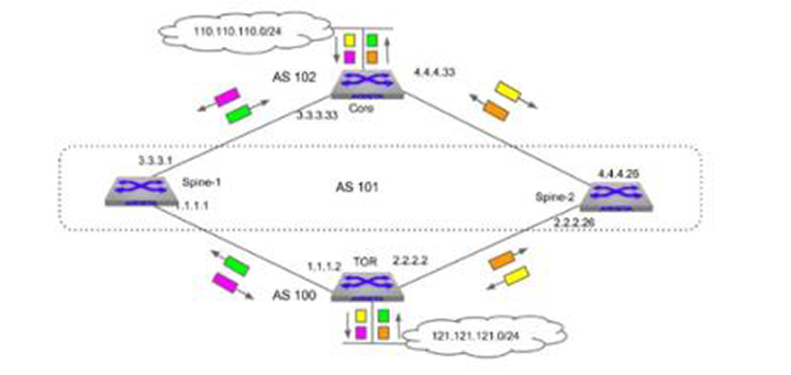
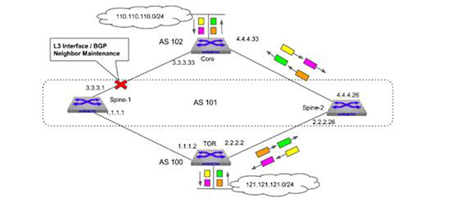
switch(config)# show maintenance units System
Unit Name: System
Origin: Built-in
Status: Not Under Maintenance
Unit Profile: Default
Time Since Last State Change: never
Bgp Groups:
AllBgpNeighborVrf-default
Interface Groups:
AllEthernetInterfaceswitch(config-maintenance)# unit System
switch(config-builtin-unit-System)# quiesce
switch(config-builtin-unit-System)# exit
switch(config-maintenance)# show maintenance
Flags:
o - On-boot maintenance
v - Violating traffic threshold
Unit Name Status Time since last change Flags
---------------------- ----------------------- -------------------------- -----
System Under Maintenance 0:02:03 ago
switch(config-maintenance)# show ip bgp summary
BGP summary information for VRF default
Router identifier 1.1.1.1, local AS number 101
Neighbor Status Codes: m - Under maintenance
Neighbor V AS MsgRcvd MsgSent InQ OutQ Up/Down State
PfxRcd PfxAcc
m 1.1.1.2 4 100 24 17 0 0 00:00:40 Estab 5 5
m 3.3.3.33 4 102 15 16 0 0 00:06:23 Estab 1 1quiesce Command Perform the following tasks to place the Unit in maintenance mode on boot-up using the quiesce command.
The on-boot property in the Unit maintenance profile
specifies that the Unit will be placed into maintenance mode during boot-up for the
specified duration. To use this method, you must perform the following tasks.
To configure the maintenance mode at the interface-level, you must perform the following tasks:
Enter configuration commands unit and quiesce using the maintenance profile bgp mode command to place the switch into maintenance mode.
The following code sequence places unit ex1, the interface 3/3, and BGP 1.1.1.1 in maintenance mode.
switch(config)# maintenance
switch(config-maintenance)# unit ex1
switch(config-unit-ex1)# quiesce
switch(config-unit-ex1)# exit
switch(config-maintenance)# interface ethernet 3/3
switch(config-maint-if-Et3/3)# quiesce
switch(config-unit-if-Et3/3)# exit
switch(config-maintenance)# bgp 1.1.1.1
switch(config-maint-bgp-1.1.1.1)# quiesce
switch(config-maint-bgp-1.1.1.1)# exit
switch(config-maintenance)#Enter configuration commands unit and no quiesce using the maintenance profile bgp mode command for the switch to exit maintenance mode.
The following code sequence causes unit ex1, the interface 3/3, and BGP 1.1.1.1 to exit maintenance mode.
switch(config)# maintenance
switch(config-maintenance)# unit ex1
switch(config-unit-ex1)# no quiesce
switch(config-unit-ex1)# exit
switch(config-maintenance)# interface ethernet 3/3
switch(config-maint-if-Et3/3)# quiesce
switch(config-unit-if-Et3/3)# exit
switch(config-maintenance)# bgp 1.1.1.1
switch(config-maint-bgp-1.1.1.1)# no quiesce
switch(config-maint-bgp-1.1.1.1)# exit
switch(config-maintenance)#Enter configuration options for the show maintenance command to fire at different stages while entering or exiting maintenance mode.
switch(config)# event-handler ex1
switch(config-handler-ex1)# trigger on-maintenance enter unit unit-ex1 all
switch(config-handler-ex1)# action bash /mnt/flash/mm-event-handler-script
switch(config-handler-ex1)# timeout 20
switch(config-handler-ex1)# exit
switch(config)#switch(config)# event-handler bar
switch(config-handler-bar)# trigger on-maintenance exit unit unit-ex1 before
stage ratemon
switch(config-handler-bar)# action bash /mnt/flash/mm-event-handler-script
switch(config-handler-bar)# exit
switch(config)#Enter the maintenance mode configuration options for groups with the maintenance and group bgp commands.
switch(config)# group interface IG1
switch(config-group-if-IG1)# interface Ethernet1
switch(config-group-if-IG1)# interface Port-Channel1,20
switch(config-group-if-IG1)# interface Vlan1-20
switch(config-group-if-IG1)# exit
switch(config)#switch(config)# group bgp BG1
switch(config-group-bgp-BG1)# neighbor 10.0.0.1
switch(config-group-bgp-BG1)# neighbor BGP_PG1
switch(config-group-bgp-BG1)# vrf vrf1
switch(config-group-bgp-BG1)# exit
switch(config)#Enter the maintenance mode configuration options for profiles with the profile interface, rate-monitoring threshold, profile bgp, and profile unit <profile_name> commands.
These command examples assign a user-configured profile as the default profile.
switch(config)# maintenance
switch(config-maintenance)# profile interface IP1
switch(config-profile-intf-IP1)# rate-monitoring load-interval 10
switch(config-profile-intf-IP1)# rate-monitoring threshold 100
switch(config-profile-intf-IP1)# shutdown max-delay 100
switch(config-profile-intf-IP1)# profile interface IP1 default
switch(config-profile-intf-IP1)# exit
switch(config-maintenance)#switch(config-maintenance)# profile bgp BP1
switch(config-profile-bgp-BP1)# initiator route-map rmap inout
switch(config-profile-bgp-BP1)# profile bgp BP1 default
switch(config-profile-bgp-BP1)# exit
switch(config-maintenance)#switch(config-maintenance)# profile unit UP1
switch(config-profile-unit-UP1)# on-boot duration 300
switch(config-profile-unit-UP1)# profile unit UP1 default
switch(config-profile-unit-UP1)# exit
switch(config-maintenance)#Enter the maintenance mode configuration options for associating profiles with groups using the maintenance and group bgp commands.
switch(config)# group interface IG1
switch(config-group-if-IG1)# maintenance profile bgp BP1
switch(config-group-if-IG1)# maintenance profile interface IP1
switch(config-group-if-IG1)#Enter the maintenance mode configuration options for units using the unit, group bgp, and maintenance commands.
switch(config)# maintenance
switch(config-maintenance)# unit ex1
switch(config-unit-ex1)# group bgp BG1
switch(config-unit-ex1)# group interface IG1
switch(config-unit-ex1)#profile unit UP1The bgp command places the switch in Maintenance Dynamic BGP Configuration mode. If no VRF specified, the BGP peer uses the default VRF.
The command creates the dynamic BGP unit if the specified dynamic BGP unit does not exist prior to issuing the command.
The no bgp vrf and default vrf commands remove the dynamic BGP unit from running-config.
Command Mode
Maintenance Configuration Mode
Command Syntax
bgp [[ipv4 | ipv6] ip_addr] [vrf vrf_name] quiesce
bgp ipv4_addr [vrf vrf_name]
bgp ipv4_addr [vrf vrf_name]
no bgp [ipv4_addr | ipv6_addr | peer_group_name][vrf vrf_name]
default bgp [ipv4_addr | ipv6_addr | peer_group_name][vrf vrf_name]Example
switch(config)# maintenance
switch(config-maintenance)# bgp 1.0.1.1
switch(config-maint-bgp-1.0.1.1)# exit
switch(config-maintenance)# bgp 1::1
switch(config-maint-bgp-1::1)# quiesce
switch(config-maint-bgp-1::1)# exit
switch(config-maintenance)# bgp PG vrf VRF1
switch(config-maint-bgp-PG)# exit
switch(config-maint-bgp-PG)# show active
maintenance
bgp 1.0.1.1
!
bgp 1::1
quiesce
!
bgp PG vrf VRF1
switch(config-maintenance)#The group bgp command places the switch in group-BGP configuration mode for configuring the members of a BGP group in a particular VRF and associating a BGP maintenance profile for these members.
The command creates the group if the specified group does not exist prior to issuing the command.
The no group bgp and default group bgp removes the BGP group.
Command Mode
Global Configuration
Command Syntax
group bgp group_name
no group bgp group_name
default group bgp group_name
Parameters
group_name name of the BGP group.
switch(config)# group bgp BG1
switch(config-group-bgp-BG1)# show active
group bgp BG1
exit
switch(config-group-bgp-BG1)#switch(config)# group bgp AllBgpNeighborVrf-default
switch(config-builtin-group-bgp-AllBgpNeighborVrf-default)#
group bgp AllBgpNeighborVrf-default
exit
switch(config-builtin-group-bgp-AllBgpNeighborVrf-default)# exit
switch(config)# show maintenance groups bgp AllBgpNeighborVrf-default
BGP Group: AllBgpNeighborVrf-default
Origin: Built-in
Neighbors:
Ipv4 Peers: 1.0.0.1, 1.0.1.2
Bgp Profile: Default
Vrf: default
Units: System
switch(config)#The group bgp <group_name> command adds a BGP group to a unit.
The no group bgp <group_name> and default group bgp <group_name> removes the BGP group from a unit.
Command Mode
Maintenance Unit Configuration
Command Syntax
group bgp group_name
no group bgp group_name
default group bgp group_name
Parameter
group_name name of the BGP group.
Example
switch(config)# maintenance
switch(config-maintenance)# unit UNIT1
switch(config-unit-UNIT1)# group bgp BG1
switch(config-unit-UNIT1)# show active
maintenance
unit UNIT1
group bgp BG1
switch(config-unit-UNIT1)The group interface command places the switch in group-intf configuration mode for configuring the members of interface group and associating a BGP/interface maintenance profile for these members.
The command creates the group if the specified group does not exist prior to issuing the command.
The no group interface <group_name> and default group interface <group_name> removes the interface group.
Command Mode
Global Configuration
Command Syntax
group interface group_name
no group interface group_name
default group interface group_name
Parameter
group_name name of the interface group.
switch(config)# group interface IG1
switch(config-group-if-IG1)# show active
group interface IG1
exit
switch(config-group-if-IG1)#switch(config)# group interface AllEthernetIntetrface
switch(config-builtin-group-if-AllEthernetInterface)# show active
group interface AllEthernetInterface
exit
switch(config-builtin-group-if-AllEthernetInterface)# exit
switch(config)# show maintenance groups interface AllEthernetInterface
Interface Group: AllEthernetInterface
Origin: Built-in
Interfaces:
Et1, Et2, Et3, Et4, Et5/1, … Et34, Et35, Et36
Profiles:
Interface Profile: Default
Bgp Profile: Default
Units: System#The group interface <group_name> command adds an interface to a unit.
The no group interface <group_name> and default group interface <group_name> removes the interface group from a unit.
Command Mode
Maintenance Unit Configuration
Command Syntax
group interface group_name
no group interface group_name
default group interface group_name
Parameter
group_name name of the interface group.
Example
switch(config)# maintenance
switch(config-maintenance)# unit UNIT1
switch(config-unit-UNIT1)# group interface IG1
switch(config-unit-UNIT1)# show active
maintenance
unit UNIT1
group interface IG1
switch(config-unit-UNIT1)The initiator route-map <route-map-name> inout command is a maintenance BGP profile configuration option for assigning the initiator route-map, which will be applied to inout (inbound and outbound).
The no initiator route-map <route-map-name> inout and default initiator route-map <route-map-name> inout removes this configuration from the BGP profile.
Command Mode
Maintenance-Profile-BGP Configuration
Command Syntax
initiator route-map route-map-name inout
no initiator route-map
default initiator route-map
Parameter
route-map-name initiator route-map name.Example
switch(config)# maintenance
switch(config-maintenance)# profile bgp BP1
switch(config-profile-bgp-BP1)# initiator route-map RM1 inout
switch(config-profile-bgp-BP1)# show active
maintenance
profile bgp BP1
initiator route-map RM1 inout
switch(config-profile-bgp-BP1)#The interface command adds interfaces to interface group.
The interface <intf-name> and default interface <intf-name> removes the interface from the group.
Command Mode
Group-Interface Configuration
Command Syntax
interface interface-name
no interface interface-name
default interface interface-name
Valid e_range, p_range, and v_range formats include number, range, or comma-delimited list of numbers and ranges. Valid Ethernet numbers depend on the Ethernet interfaces available on the switch.
Example
switch(config)# group interface IG1
switch(config-group-if-IG1)# interface Ethernet8-9
switch(config-group-if-IG1)# interface port-channel10
switch(config-group-if-IG1)# show active
group interface IG1
interface Et8-9
interface Po10
switch(config-group-if-IG1)# exit
switch(config)#The interface <intf-name> command places the switch in maintenance dynamic interface unit configuration mode.
The command creates the dynamic interface unit if the specified dynamic interface unit does not exist prior to issuing the command.
The no interface <intf-name> and default interface <intf-name> removes the dynamic interface unit from running-config.
Command Mode
Maintenance Configuration
Command Syntax
interface interface-name
no interface interface-name
default interface interface-name
Valid e_range, p_range and v_range formats include number, range, or comma-delimited list of numbers and ranges.
Commands available in maintenance dynamic interface unit configuration mode:
quiesce
Example
switch(config)# maintenance
switch(config-maintenance)# interface Ethernet1-2
switch(config-maint-if-Et1-2)# exit
switch(config-maintenance)# show active
maintenance
interface Ethernet1
!
interface Ethernet2
switch(config-maintenance)#The maintenance command allows you to enter maintenance configuration mode and specify maintenance configuration options.
The no maintenance and default maintenance command removes the maintenance configuration from the running-config.
Command Mode
Global Configuration
Command Syntax
maintenance
no maintenance
default maintenance
Example
switch(config)# maintenance
switch(config-maintenance)# profile unit foo
switch(config-profile-unit-foo)# on-boot duration 300
switch(config-profile-unit-foo)# exit
switch(config-maintenance)# unit U1
switch(config-unit-U1)# group interface IG1
switch(config-unit-U1)# group bgp BG1
switch(config-unit-U1)# profile unit foo
switch(config-unit-U1)# exit
switch(config-maintenance)# show active
maintenance
profile unit foo
on-boot duration 300
unit U1
group interface IG1
group bgp BG1
profile unit foo
switch(config-maintenance)#The maintenance profile bgp <profile-name> command associates a BGP maintenance profile to an interface/BGP group. A BGP profile can be associated to both the interface and BGP group.
The no maintenance profile bgp <profile-name> and default maintenance profile bgp <profile-name> removes the profile from the interface/BGP group.
Command Mode
Group-Interface Configuration
Group-BGP Configuration
Built-in-Group-Interface Configuration
Built-in-Group-BGP Configuration
Command Syntax
maintenance profile bgp profile-name
no maintenance profile bgp profile-name
default maintenance profile bgp profile-name
Parameter
profile name name of the BGP profile.
switch(config)# group bgp BG1
switch(config-group-bgp-BG1)# neighbor 1.0.1.1
switch(config-group-bgp-BG1)# neighbor 1::1
switch(config-group-bgp-BG1)# neighbor PG
switch(config-group-bgp-BG1)# maintenance profile bgp BP1
switch(config-group-bgp-BG1)# show active
group bgp BG1
neighbor 1.0.1.1
neighbor 1::1
neighbor PG
maintenance profile bgp BP1
switch(config-group-bgp-BG1)# exit
switch(config)#switch(config)# group interface IG1
switch(config-group-if-IG1)# interface Ethernet8-9
switch(config-group-if-IG1)# maintenance profile bgp BP1
switch(config-group-if-IG1)# show active
group interface IG1
interface Et8-9
maintenance profile bgp BP1
switch(config-group-if-IG1)# exit
switch(config)#switch(config)# group interface AllEthernetInterface
switch(config-builtin-group-if-AllEtherentInterface)# maintenance profile bgp BP1
switch(config-builtin-group-if-AllEtherentInterface)# show active
group interface AllEthernetInterface
maintenance profile bgp BP1
switch(config-builtin-group-if-AllEtherentInterface)#The maintenance profile interface <profile-name> command associates interface profile to interface group.
The no maintenance profile interface <profile-name> and default maintenance profile interface <profile-name> removes the interface profile from interface group.
Command Mode
Group-Interface Configuration
Built-in-Group-Interface Configuration
Command Syntax
maintenance profile interface profile-name
no maintenance profile interface profile-name
default maintenance profile interface profile-name
Parameter
profile-name name of the interface profile.
switch(config)# group interface IG1
switch(config-group-if-IG1)# interface Ethernet8-9
switch(config-group-if-IG1)# maintenance profile interface IP1
switch(config-group-if-IG1)# show active
group interface IG1
interface Et8-9
maintenance profile interface IP1
switch(config-group-if-IG1)#switch(config)# group interface AllEthernetInterface
switch(config-builtin-group-if-AllEtherentInterface)# maintenance profile
interface IP1
switch(config-builtin-group-if-AllEtherentInterface)# show active
group interface AllEthernetInterface
maintenance profile interface IP1
switch(config-builtin-group-if-AllEtherentInterface)#The neighbor command adds BGP peer(s) to a BGP group. The neighbors can be IPv4, IPv6, or a peer group. The no neighbor <peer> and default neighbor <peer> removes the BGP peer from the group.
Command Mode
Group-BGP Configuration
Command Syntax
neighbor [ipv4_addr | ipv6_addr | peer group name]
no neighbor [ipv4_addr | ipv6_addr | peer group name]
default neighbor [ipv4_addr | ipv6_addr | peer group name]
Example
switch(config)# group bgp BG1
switch(config-group-bgp-BG1)# neighbor 1.0.1.1
switch(config-group-bgp-BG1)# neighbor 1::1
switch(config-group-bgp-BG1)# neighbor PG
switch(config-group-bgp-BG1)# group bgp BG1
switch(config-group-bgp-BG1)# neighbor 1.0.1.1
switch(config-group-bgp-BG1)# neighbor 1::1
switch(config-group-bgp-BG1)# neighbor PG
switch(config-group-bgp-BG1)# exit
switch(config)#The on-boot duration command is a maintenance unit profile configuration option for specifying the duration after which the associated unit will be brought out of maintenance after reboot. The on-boot property in the maintenance unit profile specifies that the unit will be placed into maintenance mode as part of boot-up, and remain so for the specified duration.
The no on-boot and default on-boot removes this configuration from the unit profile.
Command Mode
Maintenance-Profile-Unit Configuration
Command Syntax
on-boot duration duration
no on-boot
default on-boot
Parameter
duration number of seconds for which unit will remain under maintenance after reboot (from 300 to 3600 seconds).
Example
switch(config)# maintenance
switch(config-maintenance)# profile unit UP1
switch(config-profile-unit-UP1)# on-boot duration 1000
switch(config-profile-unit-UP1)# show active
maintenance
profile unit UP1
on-boot duration 1000
switch(config-profile-unit-UP1)#The profile bgp command places the switch in maintenance profile BGP configuration mode for configuring initiator route-map.
The command creates the profile if the specified BGP profile does not exist prior to issuing the command.
The no profile bgp <profile-name> and default profile bgp <profile-name> removes the profile from running-config.
Command Mode
Maintenance Configuration
Command Syntax
profile bgp profile-name
no profile bgp profile-name
default profile bgp profile-name
Parameter
profile-name name of the BGP profile.
Commands available in maintenance profile BGP configuration mode:
initiator route-map (route-map name) inout
Example
switch(config)# maintenance
switch(config-maintenance)# profile bgp BP1
switch(config-profile-bgp-BP1)# show active
maintenance
profile bgp BP1
switch(config-profile-bgp-BP1)#The profile bgp <profile_name> default command configures a user-configured BGP profile as default BGP profile.
The no profile bgp <profile_name> default and default profile bgp <profile_name> default removes the user-configured BGP profile as default BGP profile.
Command Mode
Maintenance Configuration
Command Syntax
profile bgp profile_name default
no profile bgp profile_name default
default profile bgp profile_name default
Parameter
profile_name name of the BGP profile.
Example
switch(config)# maintenance
switch(config-maintenance)# profile bgp BP1
switch(config-profile-bgp-BP1)# initiator route-map RM1 inout
switch(config-profile-bgp-BP1)# exit
switch(config-maintenance)#
switch(config-maintenance)# show maintenance profile bgp default
Bgp Profile: Default
Initiator route-map: SystemGenerated
route-map SystemGenerated permit 10
Description:
description System generated initiator route-map
Match clauses:
Set clauses:
set community GSHUT additive
set local-preference 0
switch(config-maintenance)# profile bgp BP1 default
switch(config-maintenance)# show maintenance profile bgp default
Bgp Profile: BP1
Initiator route-map: RM1
switch(config-maintenance)#
switch(config-maintenance)# show active
maintenance
profile bgp BP1
initiator route-map RM1 inout
profile bgp BP1 default
switch(config-maintenance)#The profile interface command places the switch in maintenance profile interface configuration mode for configuring rate-monitoring threshold, load-interval, and shutdown max-delay.
The command creates the profile if the specified interface profile does not exist prior to issuing the command.
The no profile interface <profile-name> and default profile interface <profile-name> removes the profile from running-config.
Command Mode
Maintenance Configuration
Command Syntax
profile interface profile-name
no profile interface profile-name
default profile interface profile-name
Parameters
profile-name name of the interface profile.
Example
switch(config)# maintenance
switch(config-maintenance)# profile interface IP1
switch(config-profile-intf-IP1)# show active
maintenance
profile interface IP1
switch(config-profile-intf-IP1)#The profile interface <profile_name> default command configures a user-configured interface profile as default interface profile.
The no profile interface <profile_name> default and default profile interface <profile_name> default removes the user-configured interface profile as default interface profile.
Command Mode
Maintenance Configuration
Command Syntax
profile interface profile_name default
no profile interface profile_name default
default profile interface profile_name default
Parameter
profile_name name of the interface profile.
Example
switch(config)# maintenance
switch(config-maintenance)# profile interface IP1
switch(config-profile-intf-IP1)# rate-monitoring load-interval 100
switch(config-profile-intf-IP1)# rate-monitoring threshold 500
switch(config-profile-intf-IP1)# shutdown max-delay 100
switch(config-profile-intf-IP1)# exit
switch(config-maintenance)#
switch(config-maintenance)# show maintenance profile interface default
Interface Profile: Default
Rate Monitoring:
load-interval: 60 seconds
threshold (in/out): 100 kbps
shutdown:
enabled: no
max-delay: 300 seconds
switch(config-maintenance)#
switch(config-maintenance)# profile interface IP1 default
switch(config-maintenance)# show maintenance profile interface default
Interface Profile: IP1
Rate Monitoring:
load-interval: 100 seconds
threshold (in/out): 500 kbps
shutdown:
enabled: yes
max-delay: 100 seconds
switch(config-maintenance)#
switch(config-maintenance)# show active
maintenance
profile interface IP1 default
profile interface IP1
rate-monitoring load-interval 100
rate-monitoring threshold 500
shutdown max-delay 100
switch(config-maintenance)#The profile unit command places the switch in maintenance profile unit configuration mode for configuring on-boot duration.
The command creates the profile if the specified BGP profile does not exist prior to issuing the command.
The no profile unit <profile-name> and default profile unit <profile-name> removes the profile from running-config.
Command Mode
Maintenance Configuration
Command Syntax
profile unit profile-name
no profile unit profile-name
default profile unit profile-name
Parameter
profile-name name of the unit profile.
Commands available in maintenance profile unit configuration mode:
on-boot duration
Example
switch(config)# maintenance
switch(config-maintenance)# profile unit UP1
switch(config-profile-unit-UP1)# show active
maintenance
profile unit UP1
switch(config-profile-unit-UP1)#The profile unit <profile_name> command associates unit profile to a particular unit.
The no profile unit <profile_name> and default profile unit <profile_name> removes the unit profile from a unit.
Command Mode
Maintenance-Unit Configuration
Maintenance-Built-in-Unit Configuration
Command Syntax
profile unit profile-name
no profile unit profile-name
default profile unit profile-name
Parameter
profile-name name of the unit profile.
switch(config)# maintenance
switch(config-maintenance)# unit UNIT1
switch(config-unit-UNIT1)# group interface IG1
switch(config-unit-UNIT1)# exit
switch(config-maintenance)# show maintenance units UNIT1
Unit Name: UNIT1
Origin: User Configured
Status: Not Under Maintenance
Unit Profile: Default
Time Since Last State Change: never
Interface Groups:
IG1
switch(config-maintenance)# unit UNIT1
switch(config-unit-UNIT1)#profile unit UP1
switch(config-unit-UNIT1)# show maintenance units UNIT1
Unit Name: UNIT1
Origin: User Configured
Status: Not Under Maintenance
Unit Profile: UP1
Time Since Last State Change: never
Interface Groups:
IG1
switch(config-unit-UNIT1)# show active
maintenance
unit UNIT1
group interface IG1
profile unit UP1
switch(config-unit-UNIT1)#switch(config)# maintenance
switch(config-maintenance)#profile unit UP2
switch(config-profile-unit-UP2)# on-boot duration 600
switch(config-profile-unit-UP2)# exit
switch(config-maintenance)#
switch(config-maintenance)# unit System
switch(config-builtin-unit-System)# show active
maintenance
unit System
switch(config-builtin-unit-System)# exit
switch(config-maintenance)# show maintenance units System
Unit Name: System
Origin: Built-in
Status: Not Under Maintenance
Unit Profile: Default
Time Since Last State Change: never
Interface Groups:
AllEthernetInterface
switch(config-maintenance)#
switch(config-maintenance)# unit System
switch(config-builtin-unit-System)# profile unit UP2
switch(config-builtin-unit-System)# show active
maintenance
unit System
profile unit UP2
switch(config-builtin-unit-System)# exit
switch(config-maintenance)# show maintenance units System
Unit Name: System
Origin: Built-in
Status: Not Under Maintenance
Unit Profile: UP2
Time Since Last State Change: never
Interface Groups:
AllEthernetInterface
switch(config-maintenance)#The profile unit <profile_name> default command configures a user-configured unit profile as default unit profile.
The no profile unit <profile_name> default and default profile unit <profile_name> default removes the user-configured unit profile as default unit profile.
Command Mode
Maintenance Configuration
Command Syntax
profile unit profile_name default
no profile unit profile_name default
default profile unit profile_name default
Parameters
profile_name name of the interface profile.
Example
switch(config)# maintenance
switch(config-maintenance)# profile unit UP1
switch(config-profile-unit-UP1)# on-boot duration 1000
switch(config-profile-unit-UP1)# exit
switch(config-maintenance)#
switch(config-maintenance)# show maintenance profiles unit default
Unit Profile: Default
On-boot:
enabled: no
duration: 300 seconds
switch(config-maintenance)# profile unit UP1 default
switch(config-maintenance)# show maintenance profile unit default
Unit Profile: UP1
On-boot:
enabled: yes
duration: 1000 seconds
switch(config-maintenance)#
switch(config-maintenance)# show active
maintenance
profile unit UP1 default
profile unit UP1
on-boot duration 1000
switch(config-maintenance)#The quiesce command places a unit or dynamic interface/BGP unit into maintenance mode, gracefully transitioning traffic away from it.
The no quiesce and default quiesce exits the unit from maintenance.
Command Mode
Maintenance-Unit Configuration
Maintenance-Built-in-Unit Configuration
Maintenance Dynamic-Interface Unit Configuration
Maintenance Dynamic-Bgp Unit Configuration
Command Syntax
quiesce
no quiesce
default quiesce
Example
switch(config)# group interface IG1
switch(config-group-if-IG1)# interface Ethernet3-6
switch(config-group-if-IG1)# maintenance profile interface IP1
switch(config-group-if-IG1)# exit
switch(config)# maintenance
switch(config-maintenance)# unit UNIT1
switch(config-unit-UNIT1)# group interface IG1
switch(config-unit-UNIT1)# quiesce
switch(config-unit-UNIT1)# exit
switch(config-maintenance)# interface Ethernet1
switch(config-maint-if-Et1)# quiesce
switch(config-maint-if-Et1)# exit
switch(config-maintenance)# bgp 1.0.1.1
switch(config-maint-bgp-1.0.1.1)# quiesce
switch(config-maint-bgp-1.0.1.1)# exit
switch(config-maintenance)# bgp 1::1 vrf VRF1
switch(config-maint-bgp-1::1)# quiesce
switch(config-maint-bgp-1::1)# exit
switch(config-maintenance)# show active
maintenance
bgp 1.0.1.1
quiesce
!
bgp 1::1 vrf VRF1
quiesce
interface Et1
quiesce
unit UNIT1
quiesce
switch(config-maintenance)# show maintenance
Flags:
o - On-boot maintenance
v - Violating traffic threshold
Unit Name Status Time since last change Flags
---------------------- ----------------------- -------------------------- -----
System Not Under Maintenance never
UNIT1 Under Maintenance 0:00:06 ago
Interface Name Status Time since last change Flags
---------------------- ----------------------- -------------------------- -----
Ethernet1 Entering Maintenance 0:00:06 ago
Bgp Neighbor(vrf: defa Status Time since last change Flags
---------------------- ----------------------- -------------------------- -----
1.0.1.1 Under Maintenance 0:00:06 ago
Bgp Neighbor(vrf: VRF1 Status Time since last change Flags
---------------------- ----------------------- -------------------------- -----
1::1 Under Maintenance 0:00:06 ago
switch(config-maintenance)#The rate-monitoring load-interval command is a maintenance interface profile configuration option for configuring the interfaces rate monitoring load interval with a load interval value between 5 and 600 seconds.
Command Mode
Maintenance-Profile-Interface Configuration
Command Syntax
rate-monitoring load-interval load_interval
no rate-monitoring load-interval load_interval
default rate-monitoring load-interval load_interval
Parameter
load_interval load interval value between 5 and 600 seconds.
Example
switch(config)# maintenance
switch(config-maintenance)# profile interface IP1
switch(config-profile-intf-IP1)# rate-monitoring load-interval 10
switch(config-profile-intf-IP1)# show active
maintenance
profile interface IP1
rate-monitoring load-interval 10
switch(config-profile-intf-IP1)#The rate-monitoring threshold command is a maintenance interface profile configuration option for configuring the interfaces rate monitoring threshold with a threshold value between 1 and 4294967295 kilobytes.
The no rate-monitoring threshold and default rate-monitoring threshold removes this configuration from the interface profile.
Command Mode
Maintenance-Profile-Interface Configuration
Command Syntax
rate-monitoring threshold threshold_in_kbps
no rate-monitoring threshold threshold_in_kbps
default rate-monitoring threshold threshold_in_kbps
Parameter
threshold_in_kbps threshold in kilobytes per second (kbps) between 1 and 4294967295 kilobytes.
Example
switch(config)# maintenance
switch(config-maintenance)# profile interface IP1
switch(config-profile-intf-IP1)# rate-monitoring threshold 1000
switch(config-profile-intf-IP1)# show active
maintenance
profile interface IP1
rate-monitoring threshold 1000
switch(config-profile-intf-IP1)#The show interface command displays detailed information about the interface.
It displays an extra line that reads: Under maintenance for time in hours and minutes.
Command Mode
EXEC
Command Syntax
show interface intf_name
Parameters
Example
switch# show interface ethernet 16/1
Ethernet16/1 is up, line protocol is up (connected)
Hardware is Ethernet, address is 001c.7373.efc7
Internet address is 1.0.1.1/24
Broadcast address is 255.255.255.255
Address determined by manual configuration
IP MTU 1500 bytes, BW 40000000 kbit
Full-duplex, 40Gb/s, auto negotiation: off, uni-link: n/a
Up 4 hours, 44 minutes, 36 seconds
Under maintenance for 4 hours, 22 minutes, 26 seconds
Loopback Mode : None
2 link status changes since last clear
Last clearing of "show interface" counters 4:45:12 ago
5 minutes input rate 20 bps (0.0% with framing overhead), 0 packets/sec
5 minutes output rate 20 bps (0.0% with framing overhead), 0 packets/sec
580 packets input, 46286 bytes
Received 1 broadcasts, 0 multicast
0 runts, 0 giants
0 input errors, 0 CRC, 0 alignment, 0 symbol, 0 input discards
0 PAUSE input
601 packets output, 48954 bytes
Sent 7 broadcasts, 15 multicast
0 output errors, 0 collisions
0 late collision, 0 deferred, 0 output discards
0 PAUSE output
switch#The show interface <intf_name> status command displays an m flag if the interface is undergoing maintenance operation.
Command Mode
EXEC
Command Syntax
show interface [intf_name] status
Parameters
Example
switch# show interface Ethernet16/1 status
Port Name Status Vlan Duplex Speed Type Flags
Et1 disabled 1 auto auto 1000BASE-T
...
Et14/1 connected 2 full 40G 40GBASE-CR4
Et15/1 connected 2 full 40G 40GBASE-CR4
Et16/1 connected routed full 40G 40GBASE-CR4 m
Et17/1 notconnect 1 full 10G Not Present
...
switch#The show ip | ipv6 bgp command displays maintenance related information when relevant.
Command Mode
EXEC
Command Syntax
show ip bgp neighbors peer_addr [vrf vrf_name]
show ipv6 bgp peers peer_addr [vrf vrf_name]
Parameters
Example
switch# show ip bgp neighbors 1.0.1.2
BGP neighbor is 1.0.1.2, remote AS 300, external link
BGP version 4, remote router ID 0.0.2.1, VRF default
Negotiated BGP version 4
Last read 00:00:09, last write 00:00:11
Hold time is 180, keepalive interval is 60 seconds
Configured hold time is 180, keepalive interval is 60 seconds
Connect timer is inactive
Idle-restart timer is inactive
Session is under maintenance
BGP state is Established, up for 04:55:11
Number of transitions to established: 1
Last state was OpenConfirm
Last event was RecvKeepAlive
Neighbor Capabilities:
Multiprotocol IPv4 Unicast: advertised and received and negotiated
Four Octet ASN: advertised and received
Route Refresh: advertised and received and negotiated
Send End-of-RIB messages: advertised and received and negotiated
Additional-paths Receive:
IPv4 Unicast: advertised and received
Restart timer is inactive
End of rib timer is inactive
Message statistics:
InQ depth is 0
OutQ depth is 0
Sent Rcvd
Opens: 1 1
Notifications: 0 0
Updates: 6 2
Keepalives: 297 297
Route-Refresh: 0 0
Total messages: 304 300
Prefix statistics:
Sent Rcvd
IPv4 Unicast: 2 1
IPv6 Unicast: 0 0
Inbound updates dropped by reason:
AS path loop detection: 0
Enforced First AS: 0
Malformed MPBGP routes: 0
Originator ID matches local router ID: 0
Nexthop matches local IP address: 0
Unexpected IPv6 nexthop for IPv4 routes: 0
Nexthop invalid for single hop eBGP: 0
Inbound paths dropped by reason:
IPv4 labeled-unicast NLRIs dropped due to excessive labels: 0
Outbound paths dropped by reason:
IPv4 local address not available: 0
IPv6 local address not available: 0
Maintenance-mode:
Inbound and Outbound policy
Route map is SystemGenerated
Local AS is 200, local router ID 0.0.1.1
TTL is 1
Local TCP address is 1.0.1.1, local port is 179
Remote TCP address is 1.0.1.2, remote port is 51936
Auto-Local-Addr is disabled
TCP Socket Information:
TCP state is ESTABLISHED
Recv-Q: 0/32768
Send-Q: 0/32768
Outgoing Maximum Segment Size (MSS): 1448
Total Number of TCP retransmissions: 0
Options:
Timestamps enabled: yes
Selective Acknowledgments enabled: yes
Window Scale enabled: yes
Explicit Congestion Notification (ECN) enabled: no
Socket Statistics:
Window Scale (wscale): 9,7
Retransmission Timeout (rto): 204.0ms
Round-trip Time (rtt/rtvar): 7.5ms/3.0ms
Delayed Ack Timeout (ato): 40.0ms
Congestion Window (cwnd): 10
TCP Throughput: 15.45 Mbps
Advertised Recv Window (rcv_space): 14480The show ip | ipv6 bgp summary [ vrf <vrf_name>] command displays the m flag if the BGP IPv4 or IPv6 peer is undergoing maintenance operation.
Command Mode
EXEC
Command Syntax
show ip bgp summary [vrf vrf_name]
show ipv6 bgp summary [vrf vrf_name]
Parameter
vrf_name name of the VRF.
Example
switch# show ip bgp summary
BGP summary information for VRF default
Router identifier 0.0.1.1, local AS number 200
Neighbor Status Codes: m - Under maintenance
Neighbor V AS MsgRcvd MsgSent InQ OutQ Up/Down State PfxRcd
PfxAcc
1.0.0.1 4 100 292 296 0 0 04:47:44 Estab 1 1
m 1.0.1.2 4 300 292 296 0 0 04:47:44 Estab 1 1The show maintenance command provides brief information about all units/dynamic interface unit/dynamic bgp unit and status.
o'- flag displays that unit is undergoing or has undergone a maintenance operation because of on-boot.
v - flag displays that one/some of the interfaces are violating traffic, i.e. traffic for those interfaces is above threshold.
Command Mode
EXEC
Command Syntax
show maintenance
Example
switch# show maintenance
Flags:
o - On-boot maintenance
v - Violating traffic threshold
Unit Name Status Time since last change Flags
---------- ----------------------- ---------------------- -----
System Not Under Maintenance never
Foo Under Maintenance 0:00:40 ago o
Interface Name Status Time since last change Flags
-------------- -------------------- ---------------------- -----
Ethernet16/1 Entering Maintenance 0:00:02 ago v
Bgp Neighbor(vrf: defa Status Time since last change Flags
-------------- ---------------------- ----------------------- -----
1.0.0.2 Not Under Maintenance never
Bgp Neighbor(vrf: red) Status Time since last change Flags
------------- ----------------------- ----------------------- -----
2.0.1.2 Under Maintenance 0:00:16 ago
switch#The show maintenance bgp command displays detailed maintenance information about BGP peers.
Command Mode
EXEC
Command Syntax
show maintenance bgp ipv4_addr [vrf vrf_name] | ipv6_addr [vrf vrf_name] | peer_group [vrf vrf_name] | ip all [vrf vrf_name | vrf all] | ipv6 all [vrf vrf_name | vrf all]
Example
switch# show maintenance bgp ip all vrf all
BGP peer maintenance information for VRF default
Router identifier 0.0.1.1, local AS number 200
Neighbor: 1.0.0.1
Maintenance state: Under Maintenance
Maintenance route-map: SystemGenerated
Neighbor: 1.0.1.2
Maintenance state: Under Maintenance
Maintenance route-map: SystemGenerated
switch#The show maintenance bgp receiver route-map command displays receiver route-map which is applied during maintenance operation.
Command Mode
EXEC
Command Syntax
show maintenance bgp receiver route-map
Example
switch# show maintenance bgp receiver route-map
route-map SystemGenerated permit 10
Description:
description System generated receiver route-map
Match clauses:
match community GSHUT-LIST
SubRouteMap:
Set clauses:
route-map SystemGenerated permit 50
Description:
description System generated receiver route-map
Match clauses:
SubRouteMap:
Set clauses:
switch#This example of the show maintenance interface status quiesced command displays maintenance mode interface status details for quiesced interfaces.
switch(config)# show maintenance interface status quiesced
Flags:
v - Violating traffic threshold
s - Shutdown for maintenance
Rate (Mbps)
Interface Status In Out Flags
--------- ----------------- --- --- -----
Ethernet1 Under Maintenance 0.3 0.0 v
Ethernet2 Under Maintenance 0.0 0.0
Ethernet4 Under Maintenance 0.0 0.0
switch(config)#The show maintenance debug command displays the history of various maintenance operations on a unit/interface/BGP peer.
Command Mode
EXEC
Command Syntax
show maintenance debug bgp [peer_name] | interface [intf_name] | units [unit_name]
Example
switch# show maintenance debug interface Ethernet 16/1-4
Interface Ethernet16/1
History:
Maintenance Enter Stage Progression started 4:07:07 ago @ 2016-08-29 22:38:54
0.000000 maintEnter stages started
0.000091 stage begin started
0.000151 event begin:EventMgr started
0.004222 event begin:EventMgr completed
0.004256 stage begin is complete
0.004315 stage before_bgp started
0.004368 event before_bgp:EventMgr started
0.005820 event before_bgp:EventMgr completed
0.005843 stage before_bgp is complete
0.005904 stage bgp started
0.005947 event bgp:Rib started
0.013821 event bgp:Rib completed
0.013855 stage bgp is complete
0.013921 stage after_bgp started
0.013974 event after_bgp:EventMgr started
0.015848 event after_bgp:EventMgr completed
0.015878 stage after_bgp is complete
0.015935 stage before_ratemon started
0.015982 event before_ratemon:EventMgr started
0.017394 event before_ratemon:EventMgr completed
0.017423 stage before_ratemon is complete
0.017470 stage ratemon started
0.017506 event ratemon:MaintenanceMode started
5.021404 event ratemon:MaintenanceMode completed
5.021438 stage ratemon is complete
5.021500 stage after_ratemon started
5.021556 event after_ratemon:EventMgr started
5.023223 event after_ratemon:EventMgr completed
5.023247 stage after_ratemon is complete
5.023300 stage end started
5.023352 event end:EventMgr started
5.024683 event end:EventMgr completed
5.024705 stage end is complete
5.024762 maintEnter stages completeThe show maintenance groups command displays all the interface/BGP groups along with their members and associated profiles.
Command Mode
EXEC
Command Syntax
show maintenance groups interface | bgp group_name
Example
switch# show maintenance groups
Interface Group: AllEthernetInterface
Origin: Built-in
Interfaces:
Et1, Et2, Et3, Et4, Et5/1, Et5/2, Et5/3, Et5/4, Et6/1, Et6/2, Et6/3, Et6/4,
Et7/1, Et7/2, Et7/3, Et7/4, Et8/1, Et8/2, Et8/3, Et8/4, Et9/1, Et9/2, Et9/3,
Et9/4, Et10/1, Et10/2, Et10/3, Et10/4, Et11/1, Et11/2, Et11/3, Et11/4, Et12/1,
Et12/2, Et12/3, Et12/4, Et13/1, Et13/2, Et13/3, Et13/4, Et14/1, Et14/2, Et14/3,
Et14/4, Et15/1, Et15/2, Et15/3, Et15/4, Et16/1, Et16/2, Et16/3, Et16/4, Et17/1,
Et17/2, Et17/3, Et17/4, Et18/1, Et18/2, Et18/3, Et18/4, Et19/1, Et19/2, Et19/3,
Et19/4, Et20/1, Et20/2, Et20/3, Et20/4, Et21/1, Et21/2, Et21/3, Et21/4, Et22/1,
Et22/2, Et22/3, Et22/4, Et23/1, Et23/2, Et23/3, Et23/4, Et24/1, Et24/2, Et24/3,
Et24/4, Et25/1, Et25/2, Et25/3, Et25/4, Et26/1, Et26/2, Et26/3, Et26/4, Et27/1,
Et27/2, Et27/3, Et27/4, Et28/1, Et28/2, Et28/3, Et28/4, Et29, Et30, Et31, Et32,
Et33, Et34, Et35, Et36
Profiles:
Interface Profile: low-load-interval-profile
Bgp Profile: Default
Units: System
Interface Group: IG1
Origin: User Configured
Interfaces:
Et1, Et2, Et3, Et4, Po10, Po11, Po12
Profiles:
Interface Profile: IP1
Bgp Profile: BP1
Units: UNIT1
Bgp Group: AllBgpNeighborVrf-default
Origin: Built-in
Neighbors:
Ipv4 Peers: 1.0.0.1, 1.0.1.2
Bgp Profile: Default
Vrf: default
Units: SystemThe show maintenance interface command displays detailed information about interfaces and their maintenance status with traffic rates.
Command Mode
EXEC
Command Syntax
show maintenance interface [intf_name [detail] | detail]
Guidelines
Valid e_range, p_range, and p_range formats include number, range, or comma-delimited list of numbers and ranges.
switch# show maintenance interface
Flags:
v - Violating traffic threshold
s - Shutdown for maintenance
Rate (Mbps)
Interface Status In Out Flags
-------------------- ---------------------------- --------- ---------- ------
Ethernet1 Not Under Maintenance - -
Ethernet2 Not Under Maintenance - -
Ethernet3 Under Maintenance 0.0 0.0
Ethernet4 Not Under Maintenance - -
...
Ethernet35 Entering Maintenance 8.7 2.9
Ethernet36 Not Under Maintenance - -
switch#switch# show maintenance interface Ethernet16/1 detail
Ethernet16/1 is Under Maintenance
Groups: AllEthernetInterface
Selected profiles from Interface groups:
Interface Maintenance profile: low-load-interval-profile
Bgp Maintenance profile: Default
Bgp:
Maintenance State: Under Maintenance
Vrf: default
Neighbor: 1.0.1.2
Maintenance routemap: SystemGenerated
Rate Monitoring:
Passive monitoring since 0:42:25 ago
Total samples taken: 236
Before Maintenance:
Below threshold: 1
Above threshold: 0
After Maintenance:
Below threshold: 235
Above threshold: 0
Last sample information:
Sample taken 0:00:04 ago
In: 0.0 Mbps
Out: 0.0 Mbps
switch#The show maintenance interface status command displays maintenance status and rates for interfaces.
Command Mode
EXEC
Command Syntax
show maintenance interface status [active | entering | exiting | quiesced]
Example
switch# show maintenance interface status quiesced
Flags:
v - Violating traffic threshold
s - Shutdown for maintenance
Rate (Mbps)
Interface Status In Out Flags
-------------------- ---------------------------- ----- ------ ------
Ethernet1 Not Under Maintenance - -
Ethernet2 Not Under Maintenance - -
Ethernet3 Not Under Maintenance - -
Ethernet4 Not Under Maintenance - -
Ethernet16/1 Under Maintenance 0.0 0.0
Port-Channel10 Under Maintenance 100.5 50.5v
Port-Channel11 Entering Maintenance 15.5 10.5
Port-Channel10 Under Maintenance - -
switch#The show maintenance profiles command displays all the interface/BGP/unit profiles configuration.
Command Mode
EXEC
Command Syntax
show maintenance profiles interface | bgp | unit profile_name
Example
switch# show maintenance profiles
Interface Profile: IP1
Rate Monitoring:
load-interval: 444 seconds
threshold (in/out): 4000 Kbps
shutdown:
enabled: yes
max-delay: 399 seconds
Bgp Profile: BP1
Initiator route-map:
name: RM1
Unit Profile: UP1
On-boot:
enabled: yes
duration: 340 secondsThe show maintenance stages command displays stages of maintenance operation while entering/exiting maintenance.
Command Mode
EXEC
Command Syntax
show maintenance stages [enter | exit]
switch# show maintenance stages
No. Stage Description
--------- ------------- -----------------
1 bgp BGP Maintenance processing
2 ratemon Interface Rate Monitoring
Maintenance Exit Stage Sequence
No. Stage Description
--------- ------------- ------------------
1 ratemon Interface Rate Monitoring
2 bgp BGP Maintenance processingswitch# show maintenance stages enter
No. Stage Description
--------- ------------- --------------------
1 bgp BGP Maintenance processing
2 ratemon Interface Rate MonitoringThe show maintenance summary command displays summarized information about the maintenance mode operations such as number of units configured, number of units Entering/Exiting maintenance etc.
Command Mode
EXEC
Command Syntax
show maintenance summary
Example
switch# show maintenance summary
Number of Units Configured: 0
Number of Units Exiting Maintenance: 0
Number of Units Entering Maintenance: 0
Number of Units Not Under Maintenance: 1
Number of Units Under Maintenance: 0
Directly Put Under Maintenance:
Number of interfaces Entering Maintenance: 0
Number of interfaces Under Maintenance: 1
Number of bgp peers Entering Maintenance: 0
Number of bgp peers Under Maintenance: 1
Rate Monitoring:
Number of interfaces Entering Maintenance: 0
Number of interfaces Under Maintenance: 1
Number of interfaces Under Maintenance with threshold violation: 0
Number of interfaces shutdown for maintenance: 0
switch#The show maintenance units command displays detailed information about the particular unit.
Command Mode
EXEC
Command Syntax
show maintenance units [unit_name]
Parameters
unit_name name of unit.
Example
switch# show maintenance units
Unit Name: System
Origin: Built-in
Status: Not Under Maintenance
Unit Profile: Default
Time Since Last State Change: never
Bgp Groups:
AllBgpNeighborVrf-default
Interface Groups:
AllEthernetInterface
Unit Name: UNIT1
Origin: User Configured
Status: Under Maintenance
Unit Profile: UP1
Time Since Last State Change: 0:00:08 ago
Bgp Groups:
BG1
Interface Groups:
IG1
History:
2016-08-29 23:05:30 old state: 'maintenanceModeEnter' to new state:
'underMaintenance' 0:00:08 ago
2016-08-29 23:05:30 old state: 'active' to new state: 'maintenanceModeEnter'
0:00:08 agoThe shutdown max-delay command is a maintenance interface profile configuration option for configuring the maximum duration after which the interface is shutdown with a value between 1 and 4294967295 seconds.
The no shutdown and default shutdown removes this configuration from the interface profile.
Command Mode
Maintenance-Profile-Interface Configuration
Command Syntax
shutdown max-delay delay
no shutdown max-delay delay
default shutdown max-delay delay
Parameter
delay maximum shutdown delay between 1 and 4294967295 seconds.
Example
switch(config)# maintenance
switch(config-maintenance)# profile interface IP1
switch(config-profile-intf-IP1)# shutdown max-delay 500
switch(config-profile-intf-IP1)# show active
maintenance
profile interface IP1
shutdown max-delay 500
switch(config-profile-intf-IP1)#The trigger on-maintenance command is an event handler configuration for triggering actions during the maintenance operation of a unit, interface and BGP peer at specified stages.
The event-handler configuration takes effect only after exiting the event-handler configuration mode.
Command Mode
Event-handler Configuration
Command Syntax
trigger on-maintenance [enter | exit][unit unit_name | bgp [ipv4_addr | ipv6_addr | peer_group][vrf vrf_name] | [interface intf_name] [begin | end | all] |[before | after][stage stage_name]
switch(config)# event-handler E1
switch(config-handler-E1)# trigger on-maintenance enter unit UNIT1 all
switch(config-handler-E1)# action bash FastCli -c "show maintenance"
switch(config-handler-E1)# exit
switch(config)# show event-handler E1
Event-handler E1
Trigger: Asynchronous on-maintenance enter unit UNIT1 all delay 0 seconds
Threshold Time Window: 0 Seconds, Event Count: 1 times
Action: FastCli -c "show maintenance"
Action expected to finish in less than 10 seconds
Last Trigger Detection Time: Never
Total Trigger Detections: 0
Last Trigger Activation Time: Never
Total Trigger Activations: 0
Last Action Time: Never
Total Actions: 0
switch(config)#switch(config)# event-handler E2
switch(config-handler-E2)# trigger on-maintenance exit interface Ethernet1 before
stage bgp
switch(config-handler-E2)# action bash FastCli -c "show maintenance summary"
switch(config-handler-E2)# exit
switch(config)# show event-handler E2
Event-handler E2
Trigger: Asynchronous on-maintenance exit interface Ethernet1 before stage bgp
delay 0 seconds
Threshold Time Window: 0 Seconds, Event Count: 1 times
Action: FastCli -c "show maintenance summary"
Action expected to finish in less than 10 seconds
Last Trigger Detection Time: Never
Total Trigger Detections: 0
Last Trigger Activation Time: Never
Total Trigger Activations: 0
Last Action Time: Never
Total Actions: 0
switch(config)#switch(config)# event-handler E3
switch(config-handler-E3)# trigger on-maintenance enter bgp 1::1 vrf VRF1 end
switch(config-handler-E3)# action bash FastCli -c "show maintenance bgp ip all vrf
all"
switch(config-handler-E3)# exit
switch(config)# show event-handler E3
Event-handler E3
Trigger: Asynchronous on-maintenance enter bgp 1::1 vrf VRF1 end delay 0 seconds
Threshold Time Window: 0 Seconds, Event Count: 1 times
Action: FastCli -c "show maintenance bgp ip all vrf all"
Action expected to finish in less than 10 seconds
Last Trigger Detection Time: Never
Total Trigger Detections: 0
Last Trigger Activation Time: Never
Total Trigger Activations: 0
Last Action Time: Never
Total Actions: 0
switch(config)#The unit <unit_name> command places the switch in maintenance unit configuration mode for configuring BGP/interface groups in the unit.
The command creates the unit if the specified unit profile does not exist prior to issuing the command.
The no unit <unit-name> and default unit <unit-name> removes the unit from running-config.
Command Mode
Maintenance Configuration
Command Syntax
unit linecard [l_range | 0 l_range | unit_name]
no unit linecard [l_range | 0 l_range | unit_name]
default unit linecard [l_range | 0 l_range | unit_name]
switch(config)# maintenance
switch(config-maintenance)# unit UNIT1
switch(config-unit-UNIT1)# show active
maintenance
unit UNIT1
switch(config-unit-UNIT1)#switch(config)# maintenance
switch(config-maintenance)# unit Linecard1
switch(config-builtin-unit-Linecard1)# show active
maintenance
unit Linecard1
switch(config-builtin-unit-Linecard1)#The vrf command specifies the VRF for BGP group. All the neighbors configured in the BGP group are considered to be members of the BGP group in the particular VRF context.
The no vrf <vrf-name> and default vrf <vrf-name> removes the VRF configuration from the BGP group and sets the VRF context to default.
Command Mode
Group-BGP Configuration
Command Syntax
vrf vrf_name
no vrf vrf_name
default vrf vrf_name
Parameter
vrf_name name of the VRF in a group belonging to neighbors in that group.
Example
switch(config)# group bgp BG1
switch(config-group-bgp-BG1)# neighbor 1.0.1.1
switch(config-group-bgp-BG1)# neighbor 1::1
switch(config-group-bgp-BG1)# neighbor PG
switch(config-group-bgp-BG1)# vrf VRF1
switch(config-group-bgp-BG1)# show active
group bgp BG1
neighbor 1.0.1.1
neighbor 1::1
neighbor PG
vrf VRF1
switch(config-group-bgp-BG1)# exit
switch(config)#The switch uses rule-based lists to control packet access to ports and to select routes for redistribution to routing domains defined by dynamic routing protocols.
The following provides an introduction to Access Control Lists (ACL), Service ACLs, Route Maps, Prefix Lists, and Router Access Control List (RACL) Divergence:
The switch processes ACLs, Service ACLs, route maps, and prefix lists in order, beginning with the first rule and continuing until a match is found.
An ACL contains a list of rules that control the inbound and outbound flow of packets into Ethernet interfaces, subinterfaces, port-channel interfaces, or the switch control plane. The switch supports implementing various filtering criteria, including IP and MAC addresses and TCP/UDP ports, with include/exclude options without compromising its performance or feature set. Filtering syntax is the industry standard.
A Service ACL applies a control-plane process to control connections to, or packets processed by, the agent process.
A route map contains a list of rules that control the redistribution of IP routes into a protocol domain based on criteria such as route metrics, access control lists, next-hop addresses, and route tags. Additionally, route maps can modify route parameters during redistribution.
A prefix list contains a list of rules that defines route redistribution access for a specified IP address space. Route maps often use prefix lists to filter routes.
ACLs can also be made dynamic using payload, turning them into a User-Defined Field (UDF) alias for use in other ACLs.
An ACL is an ordered list of rules that defines access restrictions for the entities (the control plane or an interface) to which it is applied. Route maps also use ACLs to select routes for redistribution into specified routing domains.
ACL rules specify the data to which packet contents are compared when filtering data.
Upon its arrival at an interface, the switch compares a packet’s fields to the first rule of the ACL applied to the interface. Packets that match the rule are forwarded (permit rule) or dropped (deny rule). The process continues whereby the switch compares packets that do not match the rule to the next rule in the list and continues until the packet either matches a rule or the rule list is exhausted. The interface drops packets that do not match a rule.
The sequence number designates the rule's placement in the ACL.
The switch compares an ACL rule's command list to inbound and outbound packet fields. When all of a rule’s criteria match a packet’s contents, the interface performs the action specified by the rule.
The set of available commands depends on the ACL type and the specified protocol within the rule. The following is a list of commands available for supported ACL types:
Standard ACLs filter only on the source address.
Lists created in one mode cannot be modified in any other mode.
A sequence number determines a rule's position within a list. New rules are inserted into a list based on their sequence numbers. You can reference a rule's sequence number to delete it from a list.
ACL Configuration describes procedures for configuring ACLs.
Implement an Access Control List (ACL) by assigning the list to an Ethernet interface, subinterface, port channel interface, or control plane. The switch assigns a default ACL to the control plane unless the configuration contains a valid control-plane ACL assignment statement. Ethernet and port-channel interfaces are not assigned an ACL by default. Apply standard ACLs to interfaces in the same manner as other ACLs.
IPv4 and MAC ACLs are separately applied for inbound and outbound packets. An interface or subinterface can be assigned multiple ACLs, with a limit of one ACL per packet direction per ACL type. A subset of all available switches supports Egress ACLs. The control plane does not support egress ACLs.
Applying ACLs describes procedures for applying ACLs to interfaces or the control plane.
ACL rules provide a log option that produces a log message when a packet matches the rule. ACL logging creates a syslog entry when a packet matches an ACL rule where logging is enabled. Packets that match a logging-enabled ACL rule are copied to the CPU by the hardware. These packets trigger the creation of a syslog entry. The information provided in the entry depends on the ACL type or the protocol specified by the ACL. The system applies hardware rate limiting to packets written to the CPU, which prevents potential Denial-of-Service attacks. The logging rate is also limited in software to avoid creating syslog lists that are too large for human operators to use in practical ways.
ACL Rule Tracking Configuration describes procedures for configuring and enabling ACL logging.
The system assigns an ACL counter to each ACL rule. The activity of the ACL counters for rules within a list depends on the list’s counter state. When the list is in a counting state, the ACL counter of a rule increments when the rule matches a packet. When the list is in a non-counting state, the counter does not increment. A list’s counter state applies to all rules in the ACL. The default state for new ACLs is non-counting.
The system maintains the values of the counters for all rules in the list when an ACL changes from a counting state to a non-counting state or is no longer applied to any interfaces that increment counters. The counters do not reset. When the ACL returns to counting mode or is applied to an interface that increments counters, the counter operation continues from its last value.
Counters never decrement and are reset only through CLI commands.
ACL Rule Tracking Configuration describes procedures for configuring and enabling ACL counters.
Egress ACL counters count the number of packets matching rules associated with egress ACLs applied to various interfaces in a switch. 7050 and 7060 series switches maintain these counters for every TCAM rule. On these platforms, commands such as show platform trident tcam, show platform trident counters, and show ip access-list always display packet counters greater than zero.
Other switches do not enable counters by default. You must configure counters for each ACL. The show hardware counter and show ip access-list commands display the counters.
7050 and 7060 series switches enable egress ACL counters and do not require configuration.
For other platforms, to enable egress ACL counters for a specific ACL, use the counters per-entry command in the ACL's configuration mode.
Example
As shown in the following example, configure the counters per-entry command in the ACL configuration mode.
switch(config)# ip access-list acl1
switch(config-acl-acl1)# counters per-entry
7050 and 7060 series switches enable egress counters.
For other switches, enable IPv4 and IPv6 egress ACL counters in the global configuration mode using the hardware counter feature acl out command.
Example
switch(config)# hardware counter feature acl out ipv4
switch(config)#
switch(config)# hardware counter feature acl out ipv6
switch(config)#
For 7050 and 7060 series switches, egress counters cannot be disabled.
For other switches, disable IPv4 and IPv6 egress ACL counters in the global configuration mode by using the hardware counter feature acl out command.
The following examples show how to disable IPv4 and IPv6 egress ACL counters:
switch(config)# no hardware counter feature acl out ipv4
switch(config)#
switch(config)# no hardware counter feature acl out ipv6
switch(config)#
The counters roll over when the counter value for an ACL rule exceeds 2^64 (2 to the power of 64).
Example
In the following example, the hardware counter feature acl ipv6 out command is configured using units and packets.
switch(config)# hardware counter feature acl ipv6 out units packets
switch(config)#
The clear ip access-lists counters command clears the counters for all of the IPv4 ACLs or a specific IPv4 ACL, either globally or per CLI session.
Example
In the following example the ACL list named red is selected.
switch(config)# clear ip access-list counters red session
switch(config)#
The IPv6 egress ACL counters do not work in unshared mode.
Example
Use the hardware access-lists resource sharing vlan ipv6 out command to enable egress IPv6 ACL sharing.
switch(config)# hardware access-list resource sharing vlan ipv6 out
switch(config)#
The clear ipv6 access-list counters command clears the counters for all of the IPv6 ACLs or a specific IPv6 ACL, either globally or per CLI session.
Example
In the following example the ACL list named green is selected.
switch(config)# clear ipv6 access-list counters green session
switch(config)#
Use the following show commands to display information on Egress ACL Counters.
switch(config)# show ip access-list acl1
IP Access List acl1
counter per-entry
10 deny ip 11.1.1.0/24 any dscp af11
20 deny ip any any [match 39080716, 0:00:00 ago]
Total rules configured: 2
Configured on Ingress: Et2/1
Active on Ingress: Et2/1
switch(config)# show ipv6 access-list acl1
IPV6 Access List acl1
counter per-entry
10 permit ipv6 any any [match 3450000, 0:00:10 ago]
20 deny ipv6 any any
Total rules configured: 2
Configured on Ingress: Et2/1
Active on Ingress: Et2/1
switch(config)# show hardware counter drop
Summary:
Total Adverse (A) Drops: 0
Total Congestion (C) Drops: 0
Total Packet Processor (P) Drops: 250
Type Chip CounterName : Count : First Occurrence : Last Occurrence
-------------------------------------------------------------------------------
P Fap0 EgressAclDropCounter : 250 : 2015-11-11 22:39:02 : 2015-11-11 22:51:44
The switch enters the appropriate ACL Configuration Mode for the list. When adding the name of an existing ACL to the command, subsequent commands edit that list (see Modifying an ACL for additional information).
switch(config)# ip access-list test1
switch(config-acl-test1)#
switch(config)# ip access-list standard stest1
switch(config-std-acl-stest1)#
switch(config)# mac access-list mtest1
switch(config-mac-acl-mtest1)#
ACL Configuration Modes are group-change modes. Changes made in a group-change mode are saved when exiting the mode. To discard changes, use the abort command instead of exit.
switch(config-acl-test1)# permit ip 10.10.10.0/24 any
switch(config-acl-test1)# permit ip any host 10.20.10.1
switch(config-acl-test1)# deny ip host 10.10.10.1 host 10.20.10.1
To view the edited list, use the show command.
switch(config-acl-test1)# show
IP Access List test1
10 permit ip 10.10.10.0/24 any
20 permit ip 10.30.10.0/24 host 10.20.10.1
30 deny ip host 10.10.10.1 host 10.20.10.1
40 permit ip any any
Because EOS has not saved the changes, the ACL remains empty, as displayed by show ip access-lists.
switch(config-acl-test1)# show ip access-lists test1
switch(config-acl-test1)#
Use the exit command to save all current changes to the ACL and exit the ACL configuration mode.
switch(config-acl-test1)# exit
switch(config)# show ip access-lists test1
IP Access List test1
10 permit ip 10.10.10.0/24 any
20 permit ip 10.30.10.0/24 host 10.20.10.1
30 deny ip host 10.10.10.1 host 10.20.10.1
40 permit ip any any
Total rules configured: 4
Configured on Ingress: Et1/1
Active on Ingress: Et1/1
switch(config)# int et1/1
switch(config-if-Et1/1)# ip access-group test1 in
switch(config-if-Et1/1)# exit
switch(config)#
switch(config)# show ip access-lists test1
IP Access List test1
10 permit ip 10.10.10.0/24 any
20 permit ip 10.30.10.0/24 host 10.20.10.1
30 deny ip host 10.10.10.1 host 10.20.10.1
40 permit ip any any
Total rules configured: 4
Configured on Ingress: Et1/1
Active on Ingress: Et1/1
The abort command exits ACL Configuration mode without saving pending changes.
switch(config-acl-test1)# permit ip 10.10.10.0/24 any
switch(config-acl-test1)# permit ip any host 10.20.10.1
switch(config-acl-test1)# deny ip host 10.10.10.1 host 10.20.10.1
To view the edited list, use the show command.
switch(config-acl-test1)# show
IP Access List test1
10 permit ip 10.10.10.0/24 any
20 permit ip 10.30.10.0/24 host 10.20.10.1
30 deny ip host 10.10.10.1 host 10.20.10.1
40 permit ip any any
To discard the changes, use the abort command. If the ACL existed before entering the ACL Configuration Mode, the abort command restores the version that existed before entering the ACL Configuration Mode. Otherwise, the show ip access-lists command displays no output.
switch(config-acl-test1)# abort
switch(config)#
An existing ACL, including those applied to interfaces, can be modified by entering the appropriate configuration mode for the ACL as described in Creating and Opening a List. By default, while modifying an ACL, all traffic is blocked on any interface using the ACL.
To avoid packet loss and interference with features like routing and dynamic NAT, you can configure the following switches to permit all traffic on Ethernet and VLAN interfaces during ACL modifications:
Use the hardware access-list update default-result permit command to configure the preceding switches.
deny rules to the appropriate ACL:
permit rules to the appropriate ACL:
To append a rule to the end of a list, enter the rule without a sequence number while in ACL configuration mode for the list. The switch computes the new rule’s sequence number by adding 10 to the last rule’s sequence number.
switch(config)# hardware access-list update default-result permit
switch(config-acl-test1)# permit ip 10.10.10.0/24 any
switch(config-acl-test1)# permit ip any host 10.20.10.1
switch(config-acl-test1)# deny ip host 10.10.10.1 host 10.20.10.1
To view the edited list, use the show command.
switch(config-acl-test1)# show
IP Access List test1
10 permit ip 10.10.10.0/24 any
20 permit ip any host 10.20.10.1
30 deny ip host 10.10.10.1 host 10.20.10.1
switch(config-acl-test1)# permit ip any any
switch(config-acl-test1)# show
IP Access List test1
10 permit ip 10.10.10.0/24 any
20 permit ip any host 10.20.10.1
30 deny ip host 10.10.10.1 host 10.20.10.1
40 permit ip any any
To insert a rule into an ACL, enter the rule with a sequence number between the existing rules’ numbers.
Switch(config-acl-test1)# 15 permit ip 10.30.10.0/24 host 10.20.10.1
Switch(config-acl-test1)# show
IP Access List test1
10 permit ip 10.10.10.0/24 any
15 permit ip 10.30.10.0/24 host 10.20.10.1
20 permit ip any host 10.20.10.1
30 deny ip host 10.10.10.1 host 10.20.10.1
40 permit ip any any
switch(config-acl-test1)# no 20
switch(config-acl-test1)# no permit ip any host 10.20.10.1
switch(config-acl-test1)# default permit ip any host 10.20.10.1
This ACL results from entering one of the preceding commands.
switch(config-acl-test1)# show
ip access list test1
10 permit ip 10.10.10.0/24 any
15 permit ip 10.30.10.0/24 host 10.20.10.1
30 deny ip host 10.10.10.1 host 10.20.10.1
40 permit ip any any
Sequence numbers determine the order of the rules in an ACL. After editing a list and deleting existing rules while inserting new rules between existing rules, the sequence number distribution may not be uniform. Resequencing rule numbers changes the sequence number of rules to provide a constant difference between adjacent rules. The resequence (ACLs) command adjusts the sequence numbers of ACL rules.
switch(config-acl-test1)# show
IP Access List test1
10 permit ip 10.10.10.0/24 any
25 permit ip any host 10.20.10.1
30 deny ip host 10.10.10.1 host 10.20.10.1
50 permit ip any any
90 remark end of list
switch(config-acl-test1)# resequence 100 20
switch(config-acl-test1)# show
IP Access List test1
100 permit ip 10.10.10.0/24 any
120 permit ip any host 10.20.10.1
140 deny ip host 10.10.10.1 host 10.20.10.1
160 permit ip any any
180 remark end of list
ACL Rules provide a log option that produces a syslog message about the packets matching a desired packet. ACL Logging creates a syslog entry when a packet matches an ACL rule with logging enabled.
switch(config-acl-test1)# 15 permit ip 10.30.10.0/24 host 10.20.10.1 log
switch(config-acl-test1)#
IPACCESS: list acl intf filter protocol src-ip(src_port) -> dst-ip(dst_port)
IPACCESS: list acl intf filter icmp src-ip(src-port) -> dst-ip(dst-port) type= n code= m
IPACCESS: list acl intf filter protocol src-ip -> dst-ip
MACACCESS: list acl intf filter vlan ether src_mac -> dst_mac
MACACCESS: list acl intf filter vlan ether ip-prt src-mac src-ip : src-prt -> dst-mac dst-ip : dst-prt
MACACCESS: list acl intf filtervlan ether src_mac src_ip -> dst_mac dst_ip
ACLs provide a command that configures as counter state as counting or non-counting. The counter state applies to all rules in the ACL. The initial state for new ACLs defaults to non-counting.
The counters per-entry (ACL configuration modes) command places the ACL in counting mode.
switch(config-acl-test1)# counters per-entry
switch(config-acl-test1)# exit
switch(config-acl-test1)# show ip access-list test1
IP Access List test1
counters per-entry
10 permit ip 10.10.10.0/24 any
20 permit ip any host 10.20.10.1
30 deny ip host 10.10.10.1 host 10.20.10.1
40 permit ip any any
50 remark end of list
Total rules configured: 5
Configured on Ingress: Et1
Active on Ingress: Et1
The clear ip access-lists counters and clear ipv6 access-lists counters commands set the IP access list counters to zero for the specified IP access list.
switch(config)# clear ip access-lists counters test1
switch(config)#
Display ACLs using the show running-config command. The show ip access-lists command also displays ACL rosters and contents as specified by command parameters.
When editing an ACL, the show (ACL configuration modes) command displays the current or pending list as specified by command parameters.
To display the roster of ACLs on the switch, use the show [ip | ipv6 | mac] access-lists command with the summary option.
switch(config)# show ip access-lists summary
IPV4 ACL default-control-plane-acl
Total rules configured: 12
Configured on: control-plane
Active on : control-plane
IPV4 ACL list2
Total rules configured: 3
IPV4 ACL test1
Total rules configured: 6
IPV4 ACL test_1
Total rules configured: 1
IPV4 ACL test_3
Total rules configured: 0
switch(config)#
Each command can display the contents of one ACL or of all ACLs of the type specified by the command:
ACLs in counting mode display the number of inbound packets matching each rule in the list and the elapsed time since the last match.
switch# show ip access-lists default-control-plane-acl
IP Access List default-control-plane-acl [readonly]
counters per-entry
10 permit icmp any any
20 permit ip any any tracked [match 1725, 0:00:00 ago]
30 permit ospf any any
40 permit tcp any any eq ssh telnet www snmp bgp https
50 permit udp any any eq bootps bootpc snmp [match 993, 0:00:29 ago]
60 permit tcp any any eq mlag ttl eq 255
70 permit udp any any eq mlag ttl eq 255
80 permit vrrp any any
90 permit ahp any any
100 permit pim any any
110 permit igmp any any [match 1316, 0:00:23 ago]
120 permit tcp any any range 5900 5910
Total rules configured: 12
Configured on Ingress: control-plane(default VRF)
Active on Ingress: control-plane(default VRF)
switch# show ip access-lists
IP Access List default-control-plane-acl [readonly]
counters per-entry
10 permit icmp any any
20 permit ip any any tracked [match 1371, 0:00:00 ago]
30 permit ospf any any
40 permit tcp any any eq ssh telnet www snmp bgp https
50 permit udp any any eq bootps bootpc snmp
60 permit tcp any any eq mlag ttl eq 255
70 permit udp any any eq mlag ttl eq 255
80 permit vrrp any any
90 permit ahp any any
100 permit pim any any
110 permit igmp any any [match 1316, 0:00:23 ago]
120 permit tcp any any range 5900 5910
Total rules configured: 12
Configured on Ingress: control-plane(default VRF)
Active on Ingress: control-plane(default VRF)
IP Access List list2
10 permit ip 10.10.10.0/24 any
20 permit ip 10.30.10.0/24 host 10.20.10.1
30 permit ip any host 10.20.10.1
40 deny ip host 10.10.10.1 host 10.20.10.1
50 permit ip any any
Total rules configured: 5
Configured on Ingress: Et1/1
Active on Ingress: Et1/1
IP Access List test1
switch(config)#
The examples in this section display previously configured ACL commands.
The configuration stores these parameters:
10 permit ip 10.10.10.0/24 any
20 permit ip any host 10.21.10.1
30 deny ip host 10.10.10.1 host 10.20.10.1
40 permit ip any any
50 remark end of list
The current edit session removed this command, and the change not yet stored to the running-config:
20 permit ip any host 10.21.10.1
The current edit session added these commands to the ACL, and the change not yet stored to the running-config:
20 permit ip 10.10.0.0/16 any
25 permit tcp 10.10.20.0/24 any
45 deny pim 239.24.124.0/24 10.5.8.4/30
switch(config-acl-test_1)# show pending
IP Access List test_1
10 permit ip 10.10.10.0/24 any
20 permit ip 10.10.0.0/16 any
25 permit tcp 10.10.20.0/24 any
30 deny ip host 10.10.10.1 host 10.20.10.1
40 permit ip any any
45 deny pim 239.24.124.0/24 10.5.8.4/30
50 remark end of list
switch(config-acl-test_1)# show active
IP Access List test_1
10 permit ip 10.10.10.0/24 any
20 permit ip any host 10.21.10.1
30 deny ip host 10.10.10.1 host 10.20.10.1
40 permit ip any any
50 remark end of list
The following command displays the difference between the saved and modified ACLs.
switch(config-acl-test_1)# show diff
---
+++
@@ -1,7 +1,9 @@
IP Access List test_1
10 permit ip 10.10.10.0/24 any
- 20 permit ip any host 10.21.10.1
+ 20 permit ip 10.10.0.0/16 any
+ 25 permit tcp 10.10.20.0/24 any
30 deny ip host 10.10.10.1 host 10.20.10.1
40 permit ip any any
+ 45 deny pim 239.24.124.0/24 10.5.8.4/30
The following show commands display Egress ACL Counters information.
switch(config)# show ip access-list acl1
IP Access List acl1
counter per-entry
10 deny ip 11.1.1.0/24 any dscp af11
20 deny ip any any [match 39080716, 0:00:00 ago]
Total rules configured: 2
Configured on Ingress: Et2/1
Active on Ingress: Et2/1
switch(config)# show ipv6 access-list acl1
IPV6 Access List acl1
counter per-entry
10 permit ipv6 any any [match 3450000, 0:00:10 ago]
20 deny ipv6 any any
Total rules configured: 2
Configured on Ingress: Et1/1
Active on Ingress: Et1/1
switch(config)# show hardware counter drop
Summary:
Total Adverse (A) Drops: 0
Total Congestion (C) Drops: 0
Total Packet Processor (P) Drops: 250
Type Chip CounterName : Count : First Occurrence : Last Occurrence
-------------------------------------------------------------------------------
P Fap0 EgressAclDropCounter : 250 : 2015-11-11 22:39:02 : 2015-11-11 22:51:44
To configure per-port per-VLAN Quality of Service (QoS), first configure the ACL policing for QoS and then apply the policy map on a single Ethernet or port-channel interface on a per-port per-VLAN basis. The per port per VLAN QoS allows a class map to match traffic for a single VLAN or for a range of VLANs separated by commas. Per-port per-VLAN only works with QoS-based class maps.
switch# config
switch(config)# hardware tcam profile qos
switch(config)# ip access-list acl1
switch(config-acl-acl1)# permit vlan 100 0xfff ip any any
switch(config-acl-acl1)# exit
switch(config)# class-map match-any class1
switch(config-cmap-qos-class1)# match vlan 20-40, 1000-1250, 2000
switch(config-cmap-qos-class1)# exit
The following show commands display the status, traffic hit counts, TCAM profile information, and policy maps configured on an interface.
The show policy-map command displays the policy-map information of the configured policy-map.
switch# show policy-map policy1
Service-policy policy1
Class-map: class1 (match-any)
Match: ip access-group name acl1
Police cir 512000 bps bc 96000 bytes
Class-map: class-default (match-any)
The show policy-map interface command displays the policy-map configured on an interface.
switch# show policy-map interface ethernet 1
Service-policy input: p1
Hardware programming status: Successful
Class-map: c2001 (match-any)
Match: vlan 2001 0xfff
set dscp 4
Class-map: c2002 (match-any)
Match: vlan 2002 0xfff
set dscp 8
Class-map: c2003 (match-any)
Match: vlan 2003 0xfff
set dscp 12
Access Control Lists (ACLs) are configured to permit or deny traffic between source and destination ports on Strata-based platforms. Mirror ACLs are used in mirroring traffic by matching VLAN ID of the configured ACLs. Mirror ACLs are applied for IPv4, IPv6, and MAC ACLs.
switch(config)# ip access-list acl1
switch(config-acl-acl1)# permit vlan 1234 0x0 ip any any
switch(config)# monitor session sess1 source ethernet 1 rx ip access-group acl1
switch(config)# monitor session sess1 destination ethernet 2
Access Control Lists (ACLs) become active when assigned to an interface, subinterface, or control plane. This section describes the process of adding and removing ACL interface assignments.
IPv4, IPv6, and MAC ACLs are separately applied for inbound and outbound packets. You can assign an interface or subinterface with multiple ACLs, with a limit of one ACL per packet direction per ACL type. A subset of all available switches support Egress ACLs. IPv6 egress ACLs have limited availability, and IPv6 egress ACLs applied to routed interfaces or subinterfaces across the same chip on the DCS-7500E and the DCS-7280E series can be shared. In addition to that, the DSCP value can match on IPv6 egress ACLs. This ability results in more efficient utilization of system resources and is particularly useful for environments with few, potentially large, IPv6 egress ACLs applied across multiple routed interfaces.
switch(config)# interface ethernet 3
switch(config-if-Et3)# ip access-group test1 in
switch(config-if-Et3)# show running-config interfaces ethernet 3
interface Ethernet3
ip access-group test1 in
switch(config-if-Et3)#
switch(config)# control-plane
switch(config-cp)# ip access-group test_cp in
switch(config)# hardware access-list resource sharing vlan ipv6 out
switch(config)#
switch(config)# no hardware access-list resource sharing vlan ipv6 out
switch(config)#
switch(config)# interface ethernet 5.1
switch(config-if-Et5.1)# ipv4 access-group test_ACL in
switch(config-if-Et5.1)#
The no ip access-group command removes an IP ACL assignment statement from running-config for the configuration mode interface. After removing an ACL, the interface is no longer associated with an IP ACL.
The no mac ip access-group command removes a MAC ACL assignment statement from running-config for the configuration mode interface. After removing a MAC ACL is removed, the interface is no longer associated with an MAC ACL.
To remove an ACL from the control plane, enter the no ip access-group command in control plane configuration mode. Removing the control plane ACL command from running-config reinstates default-control-plane-acl as the control plane ACL.
switch(config)# interface ethernet 3
switch(config-if-Et3)# no ip access-group test in
switch(config-if-Et3)#
switch(config)# control-plane
switch(config-cp)# no ip access-group test_cp in
switch(config-cp)#
Service ACL enforcement is a feature added to a control plane service (the SSH server, the SNMP server, routing protocols, etc.) that allows the switch administrator to restrict the processing of packets and connections by the control plane processes that implement that service. The control plane program run by the control plane process checks already received packets and connections against a user-configurable Access Control List (ACL), a Service ACL.
The Service ACL contains permit and deny rules matching any source address, destination address, and TCP or UDP ports of received packets or connections. After receiving a packet or connection, the control plane process evaluates the packet or connection against the rules of the Service ACL configured for the control plane process. If the received packet or connection matches a deny rule, the control plane process drops or closes it without further processing.
Control Plane Process Enforced Access Control enables the system administrator to restrict which systems on the network can access the services provided by the switch. Each service has its own access control list, giving the system administrator fine-grained control over access to the switch's control plane services. The CLI for this uses the familiar pattern of access control lists assigned for a specific purpose, in this case, for each control plane service.
To apply the SSH Server Service ACLs for IPv4 and IPv6 traffic, use the ip access-group (Service ACLs) and ipv6 access-group (Service ACLs) commands in config-mgt-ssh configuration mode:
switch(config)# management ssh
switch(config-mgmt-ssh)# ip access-group <acl_name> [vrf <vrf_name>] in
switch(config-mgmt-ssh)# ipv6 access-group <acl_name> [vrf <vrf_name>] in
In Release EOS-4.19.0, all VRFs are required to use the same SSH Server Service ACL. The Service ACL assigned without the vrf keyword is applied to all VRFs where the SSH Server is enabled.
Use the following commands to display the status and counters of the SSH Server Service ACLs:
switch# show management ssh ip access-list
switch# show management ssh ipv6 access-list
Use the snmp-server community command to apply the SNMP Server Service ACLs to restrict which hosts can access SNMP services on the switch:
Example
switch(config)# snmp-server community community-name [view viewname] [ro | rw] acl_nameswitch(config)# snmp-server community community-name [view viewname] [ro | rw] ipv6 ipv6_acl_name
Use the ip access-group (Service ACLs) and ipv6 access-group (Service ACLs) commands to apply Service ACLs to the EOS Application Programming Interface (EAPI) Server:
switch(config)# management api http-commands
switch(config-mgmt-api-http-cmds)# vrf <vrf_name>
switch(config-mgmt-api-http-cmds-vrf-<vrf>)# ip access-group <acl_name>
switch(config-mgmt-api-http-cmds-vrf-<vrf>)# ipv6 access-group <ipv6_acl_name>
Use the following commands to display the status and counters of the EAPI server Service ACLs:
switch# show management api http-commands ip access-list
switch# show management api http-commands ipv6 access-list
Use the ip access-group (Service ACLs) and ipv6 access-group (Service ACLs) commands to apply Service ACLs for controlling connections to the BGP routing protocol agent:
switch(config)# router bgp <asn>
switch(config-router-bgp)# ip access-group <acl_name>
switch(config-router-bgp)# ipv6 access-group <ipv6_acl_name>
switch(config-router-bgp)# vrf <vrf_name>
switch(config-router-bgp-vrf-<vrf>)# ip access-group <acl_name>
switch(config-router-bgp-vrf-<vrf>)# ipv6 access-group <ipv6_acl_name>
Use the following commands to display the status and counters of the BGP routing protocol Service ACLs:
switch# show bgp ipv4 access-list
switch# show bgp ipv6 access-list
Unequal Cost MultiPath (UCMP) for BGP forwards traffic based on weight assignments for next hops of Equal Cost MultiPath (ECMP) routes. The system programs the weights in the Forwarding Information Base (FIB).
Devices that receive BGP routes disseminate BGP link-bandwidth extended community attribute information. These devices then program the next hops in the FIB using the received link-bandwidth values. The system appends the percentage of interface speed to the received link bandwidth extended community value of the route. It adjusts the weight ratio of the traffic sent over egress ports to forward more traffic toward the peer with a higher interface speed.
The following command enables the weight adjustment and configures the adjust auto to 62.3 percent.
switch(config-router-bgp)# neighbor group1 link-bandwidth adjust auto percent 62.3
PERCENT is a float value between 0.0 and 100.0 and is optional.
Use the ip access-group (Service ACLs) and ipv6 access-group (Service ACLs) commands to apply Service ACLs to control packets processed by the OSPF routing protocol agent:
Example
switch(config)# router ospf <id>
switch(config-router-ospf)# ip access-group <acl_name>
switch(config-router-ospf)# ipv6 access-group <ipv6_acl_name>
When using VRFs, each per VRF OSPF instance must be explicitly assigned its Service ACL.
Use the following commands to display the OSPF routing protocol Service ACLs' status and counters:
switch# show ospf ipv4 access-list
switch# show ospf ipv6 access-list
Use the access-group command to apply Service ACLs for controlling packets processed by the PIM routing protocol agent:
switch(config)# router pim
switch(config-router-pim)# ipv4
switch(config-router-pim-ipv4)# access-group <acl_name>
switch(config-router-pim-ipv4)# vrf <vrf_name>
switch(config-router-pim-vrf-<vrf>)# ipv4
switch(config-router-pim-vrf-<vrf>-ipv4)# access-group <acl_name>
Use the following command to display the status and counters of the PIM routing protocol Service ACLs.
switch# show ip pim access-list
Use the ip igmp access-group command to apply Service ACLs for controlling packets processed by the IGMP management protocol agent:
switch(config)# router igmp
switch(config-router-igmp)# ip igmp access-group <acl_name>
switch(config-router-igmp)# vrf <vrf_name>
switch(config-router-igmp-vrf-<vrf>)# ip igmp access-group <acl_name>
Use the following command to display the status and counters of the IGMP management protocol Service ACLs.
switch# show ip igmp access-list
Use the ip dhcp relay access-group and ipv6 dhcp relay access-group commands to apply Service ACLs for controlling packets processed by the DHCP relay agent:
switch(config)# ip dhcp relay access-group <acl_name> [vrf <vrf_name>]
switch(config)# ipv6 dhcp relay access-group <acl_name> [vrf <vrf_name>]
Use the following commands to display the status and counters of the DHCP relay agent Service ACLs:
switch# show ip dhcp relay access-list
switch# show ipv6 dhcp relay access-list
Use the ip access-group (Service ACLs) to apply Service ACLs for controlling packets and connections processed by the LDP MPLS label distribution protocol:
switch(config)# mpls ldp
switch(config-mpls-ldp)# ip access-group <acl_name>
Use the following command to display the status and counters of the LDP Service ACLs.
switch# show mpls ldp access-list
Use the ip access-group (Service ACLs) and ipv6 access-group (Service ACLs) commands to apply Service ACLs for controlling connections accepted by the LANZ agent:
switch(config)# queue-monitor streaming
switch(config-qm-streaming)# ip access-group <acl_name>
switch(config-qm-streaming)# ipv6 access-group <ipv6_acl_name>
Use the following command to display the status and counters of the LDP Service ACLs.
switch# show queue-monitor streaming access-lists
Use the ip access-group (Service ACLs) and ipv6 access-group (Service ACLs) commands to apply Service ACLs for controlling connections accepted by the MPLS Ping agent:
switch(config)# mpls ping
switch(config-mpls-ping)# ip access-group <acl_name> [vrf <vrf_name>]
switch(config-mpls-ping)# ipv6 access-group <ipv6_acl_name> [vrf <vrf_name>]
Use the ip access-group (Service ACLs) and ipv6 access-group (Service ACLs) commands to apply Service ACLs to the Telnet server:
switch(config)# management telnet
switch(config-mgmt-telnet)# ip access-group <acl_name> [vrf <vrf_name>] in
switch(config-mgmt-telnet)# ipv6 access-group <ipv6_acl_name> [vrf <vrf_name>] in
In EOS 4.19.0, all VRFs are required to use the same Telnet server Service ACL. The Service ACL assigned without the vrf keyword is applied to all VRFs where the Telnet server is enabled.
Use the following commands to display the status and counters of the LDP Service ACLs:
switch# show management telnet ip access-list
switch# show management telnet ipv6 access-list
Configure the ACLs on subinterfaces using the following command.
ip|ipv6 access-group acl-name in | out
Use the following command to unconfigure the ACLs on subinterfaces.
no ip|ipv6 access-group in | outConfigure a mirror session using subinterface sources and apply explicit ACLs to each source in the session. EOS only supports ingress mirroring from the Rx direction.
Use the following commands to configure a session, ACLMirror1, on Ethernet5/1.1, Ethernet5/1.2, Ethernet6/1 as the source, acl1 as the ACL group, and Ethernet 14/1 as the destination:
switch(config)# monitor session ACLMirror1 source Ethernet 5/1.1 rx
switch(config)# monitor session ACLMirror1 source Ethernet 5/1.2 rx ip access-group acl1
switch(config)# monitor session ACLMirror1 source Ethernet 6/1 rx
switch(config)# monitor session ACLMirror1 destination Ethernet 14/1Use the show monitor session command to display the session information:
switch(config)# show monitor session
Session ACLMirror1
------------------------
Programmed in HW: Yes
Source Ports:
Rx Only: Et5/1.2(IP ACL: acl1), Et5/1.1
Et6/1
Destination Ports:
Et14/1 : active
The show ip access-lists and show ipv6 access-lists commands display the summary of a configured ACL including the subinterface on which the ACL is configured and active.
show ip|ipv6 access-lists acl-name summary
Examples
switch(config)# show ip access-lists acl1 summary
IPV4 ACL acl1
Total rules configured: 1
Configured on Ingress: Et5.1
Active on Ingress: Et5.1
switch(config)# show ipv6 access-lists acl1 summary
IPV6 ACL acl1
Total rules configured: 1
Configured on Egress: Et5.1
Active on Egress: Et5.1
IPv4 ingress sharing optimizes the utilization of hardware resources by sharing them between different VLAN interfaces when they have the same ACL attached.
Larger deployments benefit from this function, where IPv4 ingress sharing is applied on multiple SVIs with member interfaces on the same forwarding ASIC. For example, a trunk port carrying multiple VLANs and an ingress sharing is applied on all VLANs; it occupies lesser hardware resources irrespective of the number of VLANs. By default, IPv4 ingress sharing is disabled on the switches.
IPv4 Egress Sharing optimizes the utilization of hardware resources by sharing TCAM entries for a group of SVIs on which IPv4 ACLs are shared. The TCAM entries are shared for all the SVIs per chip, saving a lot of hardware resources and enabling ACLs to scale to larger configurations.
Larger deployments benefit from IPv4 Egress Sharing, which is applied on multiple SVIs with member interfaces on the same forwarding ASIC. For example, a trunk port carrying multiple VLANs, and when applying Egress Sharing on all VLANs, it occupies lesser hardware resources irrespective of the number of VLANs.
By default, the system enables IPv4 Egress Sharing on the switches. However, enabling both IPv4 Egress Sharing and uRPF cannot at the same time is not possible. Disabling IPv4 RACL sharing will allow uRPF configuration and ensure the simultaneous configuration of the RACL in non-shared mode.
To enable unicast Reverse Path Forwarding (uRPF) on the switch, the IPv4 Egress Sharing must be disabled using the no hardware access-list resource sharing vlan ipv4 out command.
The no form of the command disables the switch's IPv4 Egress Sharing, allowing you to configure the uRPF.
switch# show ip access-lists summary
IPV4 ACL default-control-plane-acl [readonly]
Total rules configured: 17
Configured on Ingress: control-plane(default VRF)
Active on Ingress: control-plane(default VRF)
IPV4 ACL ipAclLimitTest
Total rules configured: 0
Configured on Egress: Vl2148,2700
Active on Egress: Vl2148,2700
switch# show vlan
VLAN Name Status Ports
----- -------------- --------- -----------------
1 default active
2148 VLAN2148 active Cpu, Et1, Et26
2700 VLAN2700 active Cpu, Et18
switch# show platform arad acl tcam detail
ip access-list ipAclLimitTest (Shared RACL, 0 rules, 1 entries, direction out,
state success, Acl Label 2)
Fap: Arad0, Shared: true, Interfaces: Vl2148, Vl2700
Bank Offset Entries
0 0 1
Fap: Arad1, Shared: true, Interfaces: Vl2148
Bank Offset Entries
0 0 1
switch# show platform arad acl tcam summary
The total number of TCAM lines per bank is 1024.
========================================================
Arad0:
========================================================
Bank Used Used % Used By
0 1 0 IP Egress PACLs/RACLs
Total Number of TCAM lines used is: 1
========================================================
Arad1:
========================================================
Bank Used Used % Used By
0 1 0 IP Egress PACLs/RACLs
Total Number of TCAM lines used is: 1
switch# show ip route
VRF name: default
Codes: C - connected, S - static, K - kernel,
O - OSPF, IA - OSPF inter area, E1 - OSPF external type 1,
E2 - OSPF external type 2, N1 - OSPF NSSA external type 1,
N2 - OSPF NSSA external type2, B I - iBGP, B E - eBGP,
R - RIP, I - ISIS, A B - BGP Aggregate, A O - OSPF Summary,
NG - Nexthop Group Static Route
Gateway of last resort is not set
C 10.1.0.0/16 is directly connected, Vlan2659
C 10.2.0.0/16 is directly connected, Vlan2148
C 10.3.0.0/16 is directly connected, Vlan2700
S 172.17.0.0/16 [1/0] via 172.24.0.1, Management1
S 172.18.0.0/16 [1/0] via 172.24.0.1, Management1
S 172.19.0.0/16 [1/0] via 172.24.0.1, Management1
S 172.20.0.0/16 [1/0] via 172.24.0.1, Management1
S 172.22.0.0/16 [1/0] via 172.24.0.1, Management1
C 172.24.0.0/18 is directly connected, Management1
switch# show platform arad ip route
Tunnel Type: M(mpls), G(gre)
-------------------------------------------------------------------------------
| Routing Table | |
|------------------------------------------------------------------------------
|VRF| Destination | | | | Acl | |
ECMP| FEC | Tunnel
| ID| Subnet | Cmd | Destination | VID | Label | MAC / CPU Code
|Index|Index|T Value
--------------------------------------------------------------------------------
|0 |0.0.0.0/8 |TRAP | CoppSystemL3DstMiss|0 | - | ArpTrap | - |1031 | -
|0 |10.1.0.0/16 |TRAP | CoppSystemL3DstMiss|2659 | - | ArpTrap | - |1030 | -
|0 |10.2.0.0/16 |TRAP | CoppSystemL3DstMiss|2148 | - | ArpTrap | - |1026 | -
|0 |10.3.0.0/16 |TRAP | CoppSystemL3DstMiss|2700 | - | ArpTrap | - |1034 | -
|0 |127.0.0.0/8 |TRAP | CoppSystemL3DstMiss|0 | - | ArpTrap | - |1031 | -
|0 |172.17.0.0/16 |TRAP | CoppSystemL3DstMiss|0 | - | ArpTrap | - |1025 | -
|0 |172.18.0.0/16 |TRAP | CoppSystemL3DstMiss|0 | - | ArpTrap | - |1025 | -
|0 |172.19.0.0/16 |TRAP | CoppSystemL3DstMiss|0 | - | ArpTrap | - |1025 | -
|0 |172.20.0.0/16 |TRAP | CoppSystemL3DstMiss|0 | - | ArpTrap | - |1025 | -
|0 |172.22.0.0/16 |TRAP | CoppSystemL3DstMiss|0 | - | ArpTrap | - |1025 | -
|0 |172.24.0.0/18 |TRAP | CoppSystemL3DstMiss|0 | - | ArpTrap | - |1032 | -
|0 |0.0.0.0/0 |TRAP | CoppSystemL3LpmOver|0 | - | SlowReceive | -
|1024 | -
|0 |10.1.0.0/32* |TRAP | CoppSystemIpBcast |0 | - | BcastReceive | -
|1027 | -
|0 |10.1.0.1/32* |TRAP | CoppSystemIpUcast |0 | - | Receive | - |32766| -
|0 |10.1.255.1/32* |ROUTE| Po1 |2659 |4094 | 00:1f:5d:6b:ce:45
| - |1035 | -
|0 |10.1.255.255/32* |TRAP | CoppSystemIpBcast |0 | - | BcastReceive | -
|1027 | -
|0 |10.2.0.0/32* |TRAP | CoppSystemIpBcast |0 | - | BcastReceive | -
|1027 | -
|0 |10.2.0.1/32* |TRAP | CoppSystemIpUcast |0 | - | Receive | - |32766| -
|0 |10.2.255.1/32* |ROUTE| Et1 |2148 |2 | 00:1f:5d:6d:54:dc |
- |1036 | -
|0 |10.2.255.255/32* |TRAP | CoppSystemIpBcast |0 | - | BcastReceive | -
|1027 | -
|0 |10.3.0.0/32* |TRAP | CoppSystemIpBcast |0 | - | BcastReceive | -
|1027 | -
|0 |10.3.0.1/32* |TRAP | CoppSystemIpUcast |0 | - | Receive | - |32766| -
|0 |10.3.255.1/32* |ROUTE| Et18 |2700 |2 | 00:1f:5d:6b:00:01 |
- |1038 | -
A route map is an ordered set of rules that controls the redistribution of IP routes into a protocol domain based on criteria such as route metrics, access control lists, next-hop addresses, and route tags. Route maps can also alter route parameters as they are redistributed.
Route maps are composed of route map statements, each consisting of a list of match and set commands.
The Set commands modify parameters for redistributed routes and are valid in permit statements.
switch# route-map MAP_1 permit 10
match as 10
set local-preference 100
A route map consists of statements with the same name and different sequence numbers. Statements filter routes by ascending order based on their sequence numbers. When a statement passes a route, the redistribution action is performed as the filter type specifies, ignoring all subsequent statements. When the statement fails the route, the statement with the smallest sequence number larger than the current one filters the route.
All route maps contain an implied final statement containing a single deny statement without a match command. This statement denies the redistribution of any routes that no other statement passes.
switch# route-map MAP_1 permit 10
match as 10
set local-preference 100
!
switch# route-map MAP_1 permit 20
match metric-type type-1
match as 100
Route Map Configuration describes route map configuration procedures.
Route map statements that contain a continue (route map) command support additional route map evaluation of routes whose parameters meet the statement’s match commands. Routes that match a statement containing a continue command are evaluated against the statement specified by the continue command.
When a route matches multiple route-map statements, the filter action (deny or permit) is determined by the last statement that the route matches. The set commands in all statements matching the route are applied to the route after the route map evaluation is complete. Multiple set commands are applied in the same order by which the route was evaluated against the statements containing them.
switch# route-map MAP_2 permit 10
match as 10
continue 20
set local-preference 100
!
switch# route-map MAP_2 deny 20
match metric-type type-1
match as 100
The route is redistributed if it passes statement 10 and is rejected by statement 20. The route is denied redistribution in all other instances. The continue command guarantees the evaluation of all routes against both statements.
To create a route map, use the route-map command, including the map name and filter type (deny or permit). If the command does not specify a number, the system assigns a default sequence number to the statement.
switch(config)# route-map map1 permit 50
switch(config-route-map-map1)#
To edit an existing route map statement, use the route-map, including the map’s name and the statement’s number. The switch enters the route map configuration mode for the statement. Subsequent match (route-map) and set (route-map) commands add the corresponding commands to the statement.
The show command displays the contents of the existing route map.
switch(config)# route-map MAP2
switch(config-route-map-MAP2)#show
Match clauses:
match as 10
match tag 333
Set clauses:
set local-preference 100
switch(config-route-map-MAP2)#
Route map configuration mode is a group-change mode. You can save changes by exiting the mode, either with an explicit exit command or by switching directly to another configuration mode. This includes switching to the configuration mode for a different route map.
The first command creates the map1 statement with a sequence number of 10. The second command is not yet saved to the route map, as displayed by the show command.
switch(config)# route-map map1 permit
switch(config-route-map-map1)# match as 100
switch(config-route-map-map1)# show
switch(config-route-map-map1)#
The exit command saves the match command.
switch(config-route-map-map1)# exit
switch(config)# show route-map map1
route-map map1 permit 10
Match clauses:
match as 100
Set clauses:
switch(config)#
The abort command discards all pending changes and exits route-map configuration mode.
switch(config)# route-map map1 permit
switch(config-route-map-map1)# match as 100
switch(config-route-map-map1)# abort
switch(config)# show route-map map1
switch(config)#
The following commands add rules to the configuration mode route map:
To insert a new statement into an existing route map, create a new statement with a sequence number that differs from any existing statement in the map.
switch(config)# route-map Map1 permit 50
switch(config-route-map-Map1)# match as 150
switch(config-route-map-Map1)# exit
switch(config)# show route-map Map1
route-map Map1 deny 10
Match clauses:
match as 10
match tag 333
Set clauses:
set local-preference 100
route-map Map1 permit 50
Match clauses:
match as 150
Set clauses:
switch(config)#
Protocol redistribution commands include a route map parameter determining the routes to be redistributed into the specified protocol domain.
switch(config)# router bgp 1
switch(config-router-bgp)# redistribute ospf route-map Map1
switch(config-router-bgp)# exit
switch(config)#
A prefix list is an ordered set of rules that defines route redistribution access for a specified IP address space. It consists of a filter action (deny or permit), an address space identifier (IPv4 subnet
address or IPv6 prefix), and a sequence number.
A prefix list is an ordered set of rules that defines route redistribution access for a specified IP address space. A prefix list rule consists of a filter action (deny or permit), a network address (IPv4 subnet or IPv6 prefix), and a sequence number. A rule may also include an alternate mask size.
The switch supports IPv4 and IPv6 prefix lists. The switch is placed in a Prefix-list configuration mode to create and edit IPv4 or IPv6 prefix lists.
IPv4 prefix lists are created or modified by adding an IPv4 prefix list rule in the Prefix-list configuration mode. Each rule includes the name of a prefix list and the sequence number, network address, and filter action. A list consists of all rules that have the same prefix-list name.
The ip prefix-list command creates a prefix list or adds a rule to an existing list. Route map match commands use prefix lists to filter routes for redistribution into OSPF, RIP, or BGP domains.
To create an IPv4 prefix list, enter the ip prefix-list command, followed by the list's name. The switch enters the IPv4 prefix-list configuration mode for the list. If the name of an existing ACL follows the command, subsequent commands edit that list.
switch(config)# ip prefix-list route-one
switch(config-ip-pfx)#
switch(config)# ip prefix-list route-one
switch(config-ip-pfx)# seq 10 deny 10.1.1.0/24
switch(config-ip-pfx)# seq 20 deny 10.1.0.0/16
switch(config-ip-pfx)# seq 30 permit 12.15.4.9/32
switch(config-ip-pfx)# seq 40 deny 1.1.1.0/24
To view the list, save the rules by exiting the Prefix-list command mode using the exit command, then re-enter the configuration mode and use the show active command.
switch(config-ip-pfx)# exit
switch(config)# ip prefix-list route-one
switch(config-ip-pfx)# show active
ip prefix-list route-one
seq 10 deny 10.1.1.0/24
seq 20 deny 10.1.0.0/16
seq 30 permit 12.15.4.9/32
seq 40 deny 1.1.1.0/24
switch(config-ip-pfx)# ip prefix-list route-one
IPv4 prefix lists are referenced in the match (route-map) command.
The switch provides an IPv6 prefix-list configuration mode for creating and modifying IPv6 prefix lists. A list can be edited only in the mode where it was created.
To create an IP ACL, enter the ipv6 prefix-list command and the list's name. The switch enters the list's IPv6 prefix-list configuration mode. If the name of an existing ACL follows the command, subsequent commands edit that list.
switch(config)# ipv6 prefix-list map1
switch(config-ipv6-pfx)#
To append a rule to the end of a list, enter the rule without a sequence number while in Prefix-List configuration mode for the list. The system derives the new rule’s sequence number by adding 10 to the last rule’s sequence number.
switch(config-ipv6-pfx)# permit 3:4e96:8ca1:33cf::/64
switch(config-ipv6-pfx)# permit 3:11b1:8fe4:1aac::/64
To view the list, save the rules by exiting the prefix-list command mode using the exit command, then re-enter the configuration mode and use the show active command.
switch(config-ipv6-pfx)# exit
switch(config)# ipv6 prefix-list map1
switch(config-ipv6-pfx)# show active
ipv6 prefix-list map1
seq 10 permit 3:4e96:8ca1:33cf::/64
seq 20 permit 3:11b1:8fe4:1aac::/64
switch(config-ipv6-pfx)#
The following command appends a rule to the end of the prefix list. The new rule’s sequence number is 30.
switch(config-ipv6-pfx)# permit 3:1bca:1141:ab34::/64
switch(config-ipv6-pfx)# exit
switch(config)# ipv6 prefix-list map1
switch(config-ipv6-pfx)# show active
ipv6 prefix-list map1
seq 10 permit 3:4e96:8ca1:33cf::/64
seq 20 permit 3:11b1:8fe4:1aac::/64
seq 30 permit 3:1bca:1141:ab34::/64
switch(config-ipv6-pfx)#
To insert a rule into a prefix list, use the seq (IPv6 Prefix Lists) command to enter a rule with a sequence number between the numbers of two existing rules.
switch(config-ipv6-pfx)# seq 15 deny 3:4400::/64
switch(config-ipv6-pfx)# exit
switch(config)# show ipv6 prefix-list map1
ipv6 prefix-list map1
seq 10 permit 3:4e96:8ca1:33cf::/64
seq 15 deny 3:4400::/64
seq 20 permit 3:11b1:8fe4:1aac::/64
seq 30 permit 3:1bca:3ff2:634a::/64
switch(config)#
To remove a rule from the configuration mode prefix list, enter no seq (see seq (IPv6 Prefix Lists)), followed by the rule's sequence number.
switch(config-ipv6-pfx)# no seq 20
switch(config-ipv6-pfx)# exit
switch(config)# show ipv6 prefix-list map1
ipv6 prefix-list map1
seq 10 permit 3:4e96:8ca1:33cf::/64
seq 15 deny 3:4400::/64
seq 30 permit 3:1bca:3ff2:634a::/64
switch(config)#
Route map match commands include an option that matches a specified prefix list.
Example
switch(config)# route-map MAP_1 permit
switch(config-route-map-MAP_1)# match ip address prefix-list PL_1
switch(config-route-map-MAP_1)# set community 500
switch(config-route-map-MAP_1)# exitUse match ip next-hop to match against next-hops in a route-map. This can be used to redistribute matching static routes into an IGP (IS-IS, OSPF, etc.).
The following example applies the match ip next-hop clause for static routes redistributed into IGPs for multi-agent mode. The following configures a static route.
switch(config)# ip route 10.20.30.0/24 1.2.3.4
The following commands configure a prefix-list:
switch (config)# ip prefix-list prefixListName
switch(config-ip-pfx)# permit 1.2.3.4/32
1.2.3.4 is a configured next-hop for static route 10.20.30.0/24.
The following commands configure a route map:
switch(config)# route-map routeMapName
switch(config-route-map-routeMapName)# match ip next-hop prefix-list prefixListName
For example, based on the route-map mentioned in the preceding command, to redistribute matching static routes into an IGP, use the following command for IS-IS:
switch(config-router-isis)# redistribute static route-map routeMapName
View redistributed routes using the following show commands.
The show ip route command displays the IP route.
switch# show ip route
VRF: default
Codes: C - connected, S - static, K - kernel,
O - OSPF, IA - OSPF inter area, E1 - OSPF external type 1,
E2 - OSPF external type 2, N1 - OSPF NSSA external type 1,
N2 - OSPF NSSA external type2, B - BGP, B I - iBGP, B E - eBGP,
R - RIP, I L1 - IS-IS level 1, I L2 - IS-IS level 2,
O3 - OSPFv3, A B - BGP Aggregate, A O - OSPF Summary,
NG - Nexthop Group Static Route, V - VXLAN Control Service,
DH - DHCP client installed default route, M - Martian,
DP - Dynamic Policy Route, L - VRF Leaked
Gateway of last resort is not set
...
I L2 10.20.30.0/24 [115/10] via 1.2.3.4, Ethernet1
Use the show isis database detail command to view routes redistributed into IS-IS.
switch# show isis database detail
IS-IS Instance: B VRF: default
IS-IS Level 1 Link State Database
LSPID Seq Num Cksum Life IS Flags
...
IS-IS Level 2 Link State Database
LSPID Seq Num Cksum Life IS Flags
0000.0000.0001.00-00 6 10364 840 L2 <>
...
Reachability : 10.20.30.0/24 Metric: 0 Type: 1 Up
...
While the preceding example applies to IS-IS, a similar approach may be taken for other IGPs, such as OSPF.
Describes the support for specifying User-Defined Fields (UDF) in Port ACLs, including IPv4, IPv6, and MAC ACLs. The purpose of the User-Defined Fields feature is to permit or deny packets based on custom offset pattern matching.
User-Defined Fields, or UDFs, are part of an access-list filter and comprise an offset, length, pattern match and mask. This describes a single portion of any incoming packet that matches the provided value.
UDFs may also be defined via aliases. Aliases can save a UDF configuration for reuse in multiple access lists or access list rules. An alias may substitute for a fully defined UDF, including the offset, pattern, and mask. The pattern or mask may be overridden when the alias is used in an access list rule.
The behavior, CLI syntax, and configuration of UDFs are identical to Traffic Steering UDF and Mirroring ACL UDF.
This section describes port ACLs with user-defined fields, including configuration instructions. Topics covered by this section include:
User-Defined Fields (UDFs) are specified as part of an access list. However, the type of access list dictates the base position of the UDF and the options available. In addition, you must configure a TCAM profile to include UDFs as part of the Port ACL feature’s key.
User-Defined Fields are defined as additional fields in the Port ACL feature’s key. By default, UDFs are not included in the keys for the Port ACL features. Adding a UDF to the key requires removing different key fields to fit within the TCAM width restrictions.
The following are example configurations of the TCAM profile.
The following configurations create a new profile based on the default profile. This new profile replaces the Layer 4 port key fields with one 16-bit UDF and one 32-bit UDF.
switch(config)# hardware tcam
switch(config-hw-tcam)# profile ipv4Udf copy default
switch(config-hw-tcam-profile-ipv4Udf)# feature acl port ip
switch(config-hw-tcam-profile-ipv4Udf-feature-acl-port-ip)# no key field l4-ops
switch(config-hw-tcam-profile-ipv4Udf-feature-acl-port-ip)# no key field l4-src-port
switch(config-hw-tcam-profile-ipv4Udf-feature-acl-port-ip)# no key field l4-dst-port
switch(config-hw-tcam-profile-ipv4Udf-feature-acl-port-ip)# key field udf-16b-1
switch(config-hw-tcam-profile-ipv4Udf-feature-acl-port-ip)# key field udf-32b-1
switch(config-hw-tcam-profile-ipv4Udf-feature-acl-port-ip)# exit
switch(config-hw-tcam-profile-ipv4Udf)# exit
switch(config-hw-tcam)# system profile ipv4Udf
Example
The following configurations match IPv4 packets based on the Identification (ID) field.
Packets ingressing into interface ethernet 7 with an ID equal to 1000 (0x03E80000) are forwarded, while packets with an ID different from 1000 are dropped.
(config)# ip access-list udfAcl
(config-acl-udfAcl)# permit ip any any payload header start offset 1 pattern 0x03E80000 mask 0x0000FFFF
(config-acl-udfAcl)# deny ip any any
(config-acl-udfAcl)# exit
(config)# interface ethernet 7
(config-if-Et7)#The following configurations create a new profile based on the default profile. This new profile replaces the destination IPv6 address key field with two 32-bit UDFs.
switch(config)# hardware tcam
switch(config-hw-tcam)# profile ipv6Udf copy default
switch(config-hw-tcam-profile-ipv6Udf)# feature acl port ipv6
switch(config-hw-tcam-profile-ipv6Udf-feature-acl-port-ipv6)# no key field dst-ipv6
switch(config-hw-tcam-profile-ipv6Udf-feature-acl-port-ipv6)# key field udf-32b-1
switch(config-hw-tcam-profile-ipv6Udf-feature-acl-port-ipv6)# key field udf-32b-2
switch(config-hw-tcam-profile-ipv6Udf-feature-acl-port-ipv6)# exit
switch(config-hw-tcam-profile-ipv6Udf)# exit
switch(config-hw-tcam)# system profile ipv6Udf
Example
The following configurations match IPv6 UDP packets based on the first 32 bits of the packet payload.
UDP packets ingressing into interface ethernet 7 that starts with 0x1234567X (where X can be any valid hexadecimal) in the payload are forwarded while dropping any other packets. The offset is set to 2 (2 x 4-byte words) to skip the UDP header.
(config)# ipv6 access-list udfAcl
(config-ipv6-acl-udfAcl)# permit udp any any payload offset 2 pattern 0x12345670 mask 0x0000000f
(config-ipv6-acl-udfAcl)# deny ipv6 any any
(config-ipv6-acl-udfAcl)# exit
(config)# interface ethernet 7
(config-if-Et7)# ipv6 access-group udfAcl in
This section describes CLI commands that this chapter references.
The clear ip access-lists counters command sets ACL counters to zero for the specified IPv4 Access Control List (ACL). The session parameter limits ACL counter clearing to the current CLI session.
Command Mode
Privileged EXEC
Command Syntax
clear ip access-lists counters acl_name scope
Example
switch(config)# clear ip access-lists counters
switch(config)#The clear ipv6 access-lists counters command sets ACL counters to zero for the specified IPv6 Access Control List (ACL). The session parameter limits ACL counter clearing to the current CLI session.
Command Mode
Privileged EXEC
Command Syntax
clear ipv6 access-lists counters [acl_name][scope]
Example
switch(config)# clear ipv6 access-lists counters
switch(config)#The continue command creates a route map statement entry that enables additional route map evaluation of routes with parameters meeting the statement matching criteria.
A statement typically contains a match (route-map) and a set (route-map) command. The evaluation of routes with settings the same as match command parameters normally ends and the statement's set commands apply to the route. Routes that match a statement containing a continue command evaluate against the statement specified by the continue command.
When a route matches multiple route map commands, the last statement that the route matches determines the filter action (deny or permit) . The set commands in all statements matching the route apply to the route after completing the route map evaluation. Multiple set commands apply in the same order by the route evaluation against the statement containing them.
The no continue and default continue commands remove the corresponding continue command from the configuration mode route map statement by deleting the corresponding command from running-config.
Command Mode
Route-Map Configuration
Command Syntax
continue next_seq
no continue next_seq
default continue next_seq
Parameters
Restrictions
A continue command cannot specify a sequence number smaller than the sequence number of the route map statement.
Related Command
route-map command enters the Route-Map Configuration Mode.
Example
switch(config)# route-map map1 deny 40
switch(config-route-map-map1)# match as 15
switch(config-route-map-map1)# continue 100
switch(config-route-map-map1)# set local-preference 50
switch(config-route-map-map1)#The counters per-entry command places the ACL in counting mode. In counting mode, the feature generally displays the number of instances in which each rule in the list matches an inbound packet and the elapsed time since the last match. However, for certain select platforms, in addition to the packet counter, ACL counters can also be enabled for byte counts when applied to data plane ACLs. Review the complete list of platforms that support byte count for data plan ACLslisted below:
The following platforms support ACL byte counting:
On the FM6000 platform, this command has no effect when used in an ACL for a PBR class map.
The no counters per-entry and default counters per-entry commands place the ACL in non-counting mode.
Command Mode
ACL Configuration
IPv6-ACL Configuration
Std-ACL Configuration
Std-IPv6-ACL Configuration
MAC-ACL Configuration
Command Syntax
counters per-entry
no counters per-entry
default counters per-entry
switch(config)# ip access-list test1
switch(config-acl-test1)# counters per-entry
switch(config-acl-test1)#
switch# show ip access-lists
IP Access List default-control-plane-acl [readonly]
counters per-entry
10 permit icmp any any
20 permit ip any any tracked [match 12041 packets, 0:00:00 ago]
30 permit ospf any any
40 permit tcp any any eq ssh telnet www snmp bgp https [match 11 packets, 1:41:07 ago]
50 permit udp any any eq bootps bootpc snmp rip [match 78 packets, 0:00:27 ago]
60 permit tcp any any eq mlag ttl eq 255
70 permit udp any any eq mlag ttl eq 255
80 permit vrrp any any
90 permit ahp any any
100 permit pim any any
110 permit igmp any any [match 14 packets, 0:23:27 ago]
120 permit tcp any any range 5900 5910
130 permit tcp any any range 50000 50100
140 permit udp any any range 51000 51100
Total rules configured: 14
Configured on Ingress: control-plane(default VRF)
Active on Ingress: control-plane(default VRF)
switch# show ip access-lists
IP Access List default-control-plane-acl [readonly]
counters per-entry
10 permit icmp any any [match 30 packets, 0:02:08 ago]
20 permit ip any any tracked [match 97777 packets, 0:00:00 ago]
30 permit udp any any eq bfd ttl eq 255
40 permit udp any any eq bfd-echo ttl eq 254
50 permit udp any any eq multihop-bfd micro-bfd sbfd
60 permit udp any eq sbfd any eq sbfd-initiator
70 permit ospf any any
80 permit tcp any any eq ssh telnet www snmp bgp https msdp ldp netconf-ssh gnmi [match 72 packets, 0:00:00 ago]
90 permit udp any any eq bootps bootpc snmp rip ntp ldp ptp-event ptp-general
100 permit tcp any any eq mlag ttl eq 255
110 permit udp any any eq mlag ttl eq 255
120 permit vrrp any any
130 permit ahp any any
140 permit pim any any
Total rules configured: 14
Configured on Ingress: control-plane(default VRF)
Active on Ingress: control-plane(default VRF)
IP Access List ipCountersTest:The ipCountersTest ACL is applied to the data plane. Hence, it displays the byte count information as shown below:
counters per-entry
10 permit tcp host 10.1.1.1 range 2000 4000 host 10.2.1.1 [match 486 bytes in 3 packets, 0:00:26 ago]
20 permit tcp host 10.1.1.1 range 14000 16000 host 10.2.1.1 [match 486 bytes in 3 packets, 0:00:18 ago]
30 permit udp host 10.1.1.1 range 62000 64000 host 10.2.1.1 [match 450 bytes in 3 packets, 0:00:00 ago]
40 permit tcp host 10.1.1.1 range 50000 52000 host 10.2.1.1 [match 486 bytes in 3 packets, 0:00:02 ago]
50 permit tcp host 10.1.1.1 range 38000 40000 host 10.2.1.1 [match 486 bytes in 3 packets, 0:00:10 ago]
60 permit tcp host 10.1.1.1 range 26000 28000 host 10.2.1.1 [match 486 bytes in 3 packets, 0:00:18 ago]
Total rules configured: 6
ipCountersTest ACL applies to the data plane and displays the byte count information.
The deny command adds a deny rule to the configuration mode IPv4 Access Control List (ACL). Interfaces with the ACL drop packets filtered by a deny rule. Sequence numbers determine rule placement in the ACL. Sequence numbers for commands without numbers derive from adding 10 to the number of the ACL's last rule.
The no deny and default deny commands remove the specified rule from the configuration mode ACL. The no sequence number (ACLs) command also removes the specified rule from the ACL.
Command Mode
ACL Configuration
Command Syntax
[seq_num] deny protocol source_addr source_port dest_addrR dest_port flags message fragments tracked dscp_filter ttl_filter log
no deny protocol source_addr source_port dest_addrR dest_port flags message fragments tracked dscp_filter ttl_filter log]
default deny protocol source_addr source_port dest_addrR dest_port flags message fragments tracked dscp_filter ttl_filter log]
Subnet addresses support discontiguous masks.
switch(config)# ip access-list text1
switch(config-acl-text1)# deny ospf 10.1.1.0/24 any
switch(config-acl-text1)#
switch(config-acl-text1)# 65 deny pim any any
switch(config-acl-text1)#The deny command adds a deny rule to the an IPv6 Access Control List (ACL). Interfaces with the ACL drop packets filtered by a deny rule. Sequence numbers determine rule placement in the ACL. Sequence numbers for commands without numbers derive from adding 10 to the number of the ACL's last rule.
The no deny and default deny commands remove the specified rule from the configuration mode ACL. The no <sequence number> (ACLs) command also removes the specified rule from the ACL.
Command Mode
IPv6-ACL Configuration
Command Syntax
seq_num deny protocol src_addr source_pt dest_addr dest_pt flag msg hop tracked dscp_filter log
no deny protocol src_addr source_pt dest_addr dest_pt flag msg hop tracked dscp_filter log
default deny protocol src_addr source_pt dest_addr dest_pt flag msg hop tracked dscp_filter log
Example
switch(config)# ipv6 access-list text1
switch(config-acl-text1)# deny ipv6 3710:249a:c643:ef11::/64 any
switch(config-acl-text1)#The deny command adds a deny rule in the IPv6 Prefix List Configuration Mode . Route map match commands use prefix lists to filter routes for redistribution into OSPF, RIP, or BGP domains. Routes are denied access when they match the prefix in a deny statement.
The no deny and default deny commands remove the specified rule from theIPv6 prefix list. The no deny command also removes the specified rule from the prefix list.
Command Mode
IPv6-pfx Configuration
Command Syntax
sequence deny ipv6_prefix mask
Example
switch(config)# ipv6 prefix-list route-five
switch(config-ipv6-pfx)# deny 3100::/64
switch(config-ipv6-pfx)#The deny command adds a deny rule to the MAC Access Control List (ACL) Configuration Mode.
Interfaces with an applied ACL drop packets filtered by a deny rule. Sequence numbers determine rule placement in the ACL. Sequence numbers for commands without numbers derive from adding 10 to the number of the ACL last rule.
The no deny and default deny commands remove the specified rule from the MAC Access Control List (ACL) Configuration Mode. The no <sequence number> (ACLs) command also removes the specified rule from the ACL.
Command Mode
MAC-ACL Configuration Mode
Command Syntax
seq_num deny source_addr dest_addr [protocol][log]
no deny source_addr dest_addr [protocol][log]
default deny source_addr dest_addr [protocol][log]
switch(config)# mac access-list text1
switch(config-mac-acl-text1)# deny 10.1000.0000 0.0.FFFF any aarp
switch(config-mac-acl-text1)# 25 deny any anyThe deny command adds a deny rule to the Standard IPv4 Access Control List (ACL) Configuration Mode. Standard ACL rules filter on the source field.
Interfaces with an applied ACL drop packets filtered by a deny rule. Sequence numbers determine rule placement in the ACL. Sequence numbers for commands without numbers derive from adding 10 to the number of the ACL last rule.
The no deny and default deny commands remove the specified rule from the Standard IPv4 Access Control List (ACL) Configuration Mode. The no sequence number (ACLs) command also removes the specified rule from the ACL.
Command Mode
Std-ACL Configuration
Command Syntax
[seq_num] deny source_addr log
no deny source_addr log
default deny source_addr log
Subnet addresses support noncontinuous masks.
Example
switch(config)# ip access-list standard text1
switch(config-std-acl-text1)# deny 10.1.1.1/24
switch(config-std-acl-text1)#The deny command adds a deny rule to the Standard IPv6 Access Control List (ACL) Configuration Mode. Standard ACL rules filter on the source field.
Interfaces with an applied ACL drop packets filtered by a deny rule. Sequence numbers determine rule placement in the ACL. Sequence numbers for commands without numbers derive from adding 10 to the number of the ACL's last rule.
The no deny and default deny commands remove the specified rule from the Standard IPv6 Access Control List (ACL) Configuration Mode. The no <sequence number> (ACLs) command also removes the specified rule from the ACL.
Command Mode
Std-IPv6-ACL Configuration
Command Syntax
seq_num deny source_addr
no deny source_addr
default deny source_addr
Example
switch(config)# ipv6 access-list standard text1
switch(config-std-acl-ipv6-text1)# deny 2103::/64
switch(config-std-acl-ipv6-text1)#The description command adds a text string to the configuration mode route map. The string has no functional impact on the route map.
The no description and default description commands remove the text string from the configuration mode route map by deleting the corresponding description command from running-config.
Command Mode
Route-Map Configuration
Command Syntax
description label_text
no description
default description
Parameter
label_text Character string assigned to the route map configuration.
Related Command
Example
switch(config)# route-map XYZ-1
switch(config-route-map-XYZ-1)# description This is the first map.
switch(config-route-map-XYZ-1)# exit
switch(config)# show route-map XYZ-1
route-map XYZ-1 permit 10
Description:
description This is the first map.
Match clauses:
Set clauses:
switch(config)#The hardware access-list resource sharing vlan in command enables the IPv4 Ingress Sharing of hardware resources on the switch when the same ACL applies to different VLANs.
The no hardware access-list resource sharing vlan in command disables the IPv4 Ingress Sharing of hardware resources on the switch.
Command Mode
Global Configuration
Command Syntax
hardware access-list resource sharing vlan [ipv4 | ipv6] in
no hardware access-list resource sharing vlan in
Use the show platform trident command to verify the Ingress IPv4 Sharing information.
The hardware access-list resource sharing vlan ipv4 out command enables IPv4 Egress RACL TCAM sharing on the switch.
The no hardware access-list resource sharing vlan ipv4 out command disables the IPv4 Egress RACL TCAM sharing on the switch. By default, the switch enables IPv4 Egress RACL sharing.
Command Mode
Global Configuration
Command Syntax
hardware access-list resource sharing vlan ipv4 out
no hardware access-list resource sharing vlan ipv4 out
Example
switch# show running-config all | include sharing
hardware access-list resource sharing vlan ipv4 out
---->It returns the following output if IPv4 RACL sharing is enabled.The hardware access-list update default-result permit command configures the switch to permit all traffic on Ethernet and VLAN interfaces with ACLs applied to them while modifying the ACLs. Permits traffic when modifying the ACL using one of the ip access-list commands, and ends when exiting the ACL Configuration Mode and rules populated in hardware. EOS disables this by default.
The no hardware access-list update default-result permit and default hardware access-list update default-result permit commands restore the switch to the default state and blocks traffic during ACL modifications by removing the corresponding hardware access-list update default-result permit command from the running-config.
Command Mode
Global Configuration
Command Syntax
hardware access-list update default-result permit
no hardware access-list update default-result permit
default hardware access-list update default-result permit
Restrictions
This command is available on the Arista 7050X, 7060X, 7150, 7250X, 7280, 7280R, 7300X, 7320X, and 7500 series switches.
When enabled, static NAT, and ACL-based mirroring are affected during ACL updates.
Example
switch(config)# hardware access-list update default-result permit
switch(config)#The hardware counter feature acl out command enables egress ACL hardware counters for IPv4 or IPv6 and count the number of packets matching rules associated with egress ACLs applied to various interfaces on a switch.
The no hardware counter feature acl out and default hardware counter feature acl out commands disable or return the egress ACL hardware counters to the default state.
Command Mode
Global Configuration
Command Syntax
hardware counter feature acl out [options [ipv4 | ipv6]
no hardware counter feature acl out [options [ipv4 | ipv6]
default hardware counter feature acl out [options [ipv4 | ipv6]
switch(config)# hardware counter feature acl out ipv4
switch(config)#
switch(config)# no hardware counter feature acl out ipv4
switch(config)#The ip access-group (Service ACLs) command configures a Service ACL to apply to a control-plane service. Specify the service by the command mode used to apply the Service ACL.
The no ip access-group and default ip access-group commands remove the corresponding ip access-group (Service ACLs) command from running-config.
Command Mode
Mgmt-SSH Configuration
Mgmt-API Configuration
Router-BGP Configuration
Router-OSPF Configuration
Router-IGMP Configuration
MPLS-LDP Configuration
Queue-Monitor-Streaming Configuration
MPLS-Ping Configuration
Mgmt-Telnet Configuration
Command Syntax
ip access-group acl_name [vrfvrf_name][in]
no ip access-group acl_name [vrfvrf_name][in]
default ip access-group acl_name [vrfvrf_name][in]
Parameters
Example
(config)# router bgp 5
(config-router-bgp)# vrf purple
(config-router-bgp-vrf-purple)# ip access-group bgpaclFor additional configuration examples, see Configuring Service ACLs and Displaying Status and Counters.
The ip access-group command applies an IPv4 or standard IPv4 Access Control List (ACL) to an interface or subinterface in the Interface Configuration Mode.
The no ip access-group and default ip access-group commands remove the corresponding ip access-group command from running-config.
Command Mode
Interface-Ethernet Configuration
Interface-Port-Channel Configuration
Interface-VLAN Configuration
Command Syntax
ip access-group list_name[direction [in | out]]
no ip access-group list_name[direction [in | out]]
default ip access-group list_name [direction [in | out]]
Considerations
Filtering of outbound packets by ACLs not supported on Petra platform switches.
Filtering of outbound packets by ACLs on FM6000 switches supported on physical interfaces only (Ethernet and port channels).
ACLs on sub-interfaces are supported on DCS-7280E, DCS-7500E, DCS-7280R, and DCS-7500R.
Example
switch(config)# interface ethernet 3
switch(config-if-Et3)# ip access-group test2 in
switch(config-if-Et3)#The ip access-list command places the switch in ACL Configuration Mode, a group change mode that modifies an IPv4 access control list. The command specifies the name of the IPv4 ACL that subsequent commands modify and creates an ACL if it references a nonexistent list. All changes in a group change mode edit session are pending until the end of the session.
The exit command saves pending ACL changes to running-config, then returns the switch to Global Configuration Mode. ACL changes are also saved by entering a different configuration mode.
The abort command discards pending ACL changes, returning the switch to Global Configuration Mode.
The no ip access-list and default ip access-list commands delete the specified IPv4 ACL.
Command Mode
Global Configuration
Command Syntax
ip access-list list_name
no ip access-list list_name
default ip access-list list_name
Parameter
list_name - Specify the name of the ACL. Must begin with an alphabetic character. Cannot contain spaces or quotation marks.
switch(config)# ip access-list filter1
switch(config-acl-filter1)#
switch(config-acl-filter1)# exit
switch(config)#switch(config-acl-filter1)# abort
switch(config)#The ip access-list standard command places the switch in STD-ACL Configuration Mode, a group change mode that modifies a standard IPv4 access control list. The command specifies the name of the standard IPv4 ACL that subsequent commands modify, and creates an ACL if it references a nonexistent list. All group change mode edit session changes are pending until the session ends.
The exit command saves pending ACL changes to running-config, then returns the switch to Global Configuration Mode. Pending changes are also saved by entering a different configuration mode.
The abort command discards pending ACL changes, returning the switch to global configuration mode.
The no ip access-list standard and default ip access-list standard commands delete the specified ACL.
Command Mode
Global Configuration
Command Syntax
ip access-list standard list_name
no ip access-list standard list_name
default ip access-list standard list_name
Parameter
list_name - Specify the name of standard ACL. Must begin with an alphabetic character. Cannot contain spaces or quotation marks.
switch(config)# ip access-list standard filter2
switch(config-std-acl-filter2)#
switch(config-std-acl-filter2)# exit
switch(config)#
switch(config-std-acl-filter2)# abort
switch(config)#The ip prefix-list command creates a prefix list or adds an entry to an existing list. Route map match commands use prefix lists to filter routes for redistribution into OSPF, RIP, or BGP domains.
A prefix list comprises all prefix list entries with the same label. The sequence numbers of the rules in a prefix list specify the order for applying rules to a route evaluated by the match command.
The no ip prefix-list and default ip prefix-list commands delete the specified prefix list entry by removing the corresponding ip prefix-list statement from running-config. If the no or default ip prefix-list command does not list a sequence number, the command deletes all entries of the prefix list.
Command Mode
Global Configuration
Command Syntax
ip prefix-list list_name [deny | permit] [seq index] network_addr [mask] resequence seq_number remark comment
no ip prefix-list list_name seq [index]
default ip prefix-list list_name seq [index]
switch(config)# ip prefix-list route-one
switch(config-ip-pfx)#
switch(config)# ip prefix-list route-one
switch(config-ip-pfx)# seq 10 deny 10.1.1.0/24
switch(config-ip-pfx)# seq 20 deny 10.1.0.0/16
switch(config-ip-pfx)# seq 30 permit 12.15.4.9/32
switch(config-ip-pfx)# seq 40 deny 1.1.1.0/24The ipv6 access-groupcommand applies an IPv6 or standard IPv6 Access Control List (ACL) to the configuration mode interface.
The no ipv6 access-group and default ipv6 access-group commands remove the corresponding ipv6 access-group command from running-config.
Command Mode
Interface-Ethernet Configuration
Interface-Port-Channel Configuration
Interface-VLAN Configuration
Command Syntax
ipv6 access-group list_name [in | out]
no ipv6 access-group list_name [in | out]
default ipv6 access-group list_name [in | out]
Examples
switch(config)# interface ethernet 3
switch(config-if-Et3)# ipv6 access-group test2 in
switch(config-if-Et3)#The ipv6 access-group (Service ACLs) command configures an IPv6 or standard IPv6 Service ACL to be applied by a control-plane service. Specify the service with the command mode to apply the Service ACL.
The no ipv6 access-group (Service ACLs) and default ipv6 access-group (Service ACLs) commands remove the corresponding ipv6 access-group (Service ACLs) command from running-config.
Command Mode
Mgmt-SSH Configuration
Mgmt-API Configuration
Router-BGP Configuration
Router-OSPF Configuration
MPLS-LDP Configuration
Queue-Monitor-Streaming Configuration
MPLS-Ping Configuration
Mgmt-Telnet Configuration
Command Syntax
ipv6 access-group ipv6_acl_name [vrf vrf_name][in]
no ipv6 access-group [ipv6_acl_name][vrfvrf_name][in]
default ipv6 access-group ipv6_acl_name [vrf vrf_name][in]
Parameters
Example
(config)# router bgp 5
(config-router-bgp)# vrf purple
(config-router-bgp-vrf-purple)# ipv6 access-group bgpacl
For additional configuration examples, see Configuring Service ACLs and Displaying Status and Counters.
The ipv6 access-list command places the switch in IPv6-ACL Configuration Mode, a group change mode that modifies an IPv6 access control list. The command specifies the name of the IPv6 ACL that subsequent commands modify and creates an ACL if it references a nonexistent list. All changes in a group change mode edit session pend until the end of the session.
The exit command saves pending ACL changes to running-config, then returns the switch to global configuration mode. ACL changes are also saved by entering a different configuration mode.
The abort command discards pending ACL changes, returning the switch to Global Configuration Mode.
The no ipv6 access-list and default ipv6 access-list commands delete the specified IPv6 ACL.
Command Mode
Global Configuration
Command Syntax
ipv6 access-list list_name
no ipv6 access-list list_name
default ipv6 access-list list_name
Parameters
list_name - Specify a name for the ACL. Must begin with an alphabetic character and cannot contain spaces or quotation marks.
switch(config)# ipv6 access-list filter1
switch(config-ipv6-acl-filter1)#
switch(config-ipv6-acl-filter1)# exit
switch(config)#
switch(config-ipv6-acl-filter1)# abort
switch(config)#The ipv6 access-list standard command places the switch in std-IPv6-ACL-configuration mode, a group change mode that modifies a standard IPv6 access control list. The command specifies the name of the standard IPv6 ACL that subsequent commands modify and creates an ACL if it references a nonexistent list. All group change mode edit session changes are pending until the session ends.
The exit command saves pending ACL changes to running-config, then returns the switch to Global Configuration Mode. Pending changes are also saved by entering a different configuration mode.
The abort command discards pending ACL changes, returning the switch to global configuration mode.
The no ipv6 access-list standard and default ipv6 access-list standard commands delete the specified ACL.
Command Mode
Global Configuration
Command Syntax
ipv6 access-list standard list_name
no ipv6 access-list standard list_name
default ipv6 access-list standard list_name
Parameters
list_name - Specify a name for the ACL. Must begin with an alphabetic character and cannot contain spaces or quotation marks.
switch(config)# ipv6 access-list standard filter2
switch(config-std-ipv6-acl-filter2)#switch(config-std-ipv6-acl-filter2)# exit
switch(config)#switch(config-std-ipv6-acl-filter2)# abort
switch(config)#The ip prefix-list command places the switch in IPv6 prefix-list configuration mode, which is a group change mode that modifies an IPv6 prefix list. The command specifies the name of the IPv6 prefix list that subsequent commands modify and creates a prefix list if it references a nonexistent list. All changes in a group change mode edit session are pending until the end of the session.
The exit command saves pending prefix list changes to running-config, then returns the switch to global configuration mode. ACL changes are also saved by entering a different configuration mode.
The abort command discards pending changes, returning the switch to global configuration mode.
The no ipv6 prefix-list and default ipv6 prefix-list commands delete the specified IPv6 prefix list.
Command Mode
Global Configuration
Command Syntax
ipv6 prefix-list list_name
no ipv6 prefix-list list_name
default ipv6 prefix-list list_name
Parameter
list_name Name of prefix list. Must begin with an alphabetic character. Cannot contain spaces or quotation marks.
switch(config)# ipv6 prefix-list route-five
switch(config-ipv6-pfx)#
switch(config-ipv6-pfx)# exit
switch(config)#
switch(config-ipv6-pfx)# interface ethernet 3
switch(config-if-Et3)#
switch(config-ipv6-pfx)# abort
switch(config)#The mac access-group command applies a MAC Access Control List (MAC ACL) when in the Interface Configuration Mode.
The no mac access-group and default mac access-group commands remove the specified mac access-group command from running-config.
Command Mode
Interface-Ethernet Configuration
Interface-Port-Channel Configuration
Command Syntax
mac access-group list_name [direction [in | out]]
no mac access-group list_name[direction [in | out]]
default mac access-group list_name [direction [in | out]]
Restrictions
Only Helix, Trident, and Trident II platform switches support filtering of outbound packets by MAC ACLs.
Example
switch(config)# interface ethernet 3
switch(config-if-Et3)# mac access-group mtest2 in
switch(config-if-Et3)#The mac access-list command places the switch in MAC-ACL Configuration Mode, a group change mode that modifies a MAC access control list. The command specifies the name of the MAC ACL that subsequent commands modify and creates an ACL if it references a nonexistent list. All changes in a group change mode edit session are pending until the end of the session.
The exit command saves pending ACL changes to running-config, then returns the switch to Global Configuration Mode. ACL changes are also saved by entering a different configuration mode.
The abort command discards pending ACL changes, returning the switch to Global Configuration Mode.
The no mac access-list and default mac access-list commands delete the specified list.
Command Mode
Global Configuration
Command Syntax
mac access-list list_name
no mac access-list list_name
default mac access-list list_name
Parameter
list_name - Specify the name of the MAC ACL. Names must begin with an alphabetic character and cannot contain a space or quotation mark.
switch(config)# mac access-list mfilter1
switch(config-mac-acl-mfilter1)#
switch(config-mac-acl-mfilter1)# exit
switch(config)#
switch(config-mac-acl-mfilter1)# interface ethernet 3
switch(config-if-Et3)#
switch(config-mac-acl-mfilter1)# abort
switch(config)#The match command creates a route map statement entry that specifies one route filtering command. When a statement contains multiple match commands, the permit or deny filter applies to a route only if the properties equal the corresponding parameters in each match command. When a route properties do not equal the command parameters, the route is evaluated against the next statement in the route map, as determined by sequence number. If all statements fail to permit or deny the route, the route is denied.
The no match and default match commands remove the match command from the configuration mode route map statement by deleting the corresponding command from running-config.
Command Mode
Route-Map Configuration
Command Syntax
match condition
no match condition
default match condition
Related Command
Examples
switch(config)# route-map map1
switch(config-route-map-map1)# match as 15
switch(config-route-map-map1)#switch(config-route-map-map1)# match as-path length <= 300
switch(config-route-map-map1)#The no sequence number command removes the rule with the specified sequence number from the ACL. The default <sequence number> command also removes the specified rule.
Command Mode
ACL Configuration
IPv6-ACL Configuration
Std-ACL Configuration
Std-IPv6-ACL Configuration
MAC-ACL Configuration
Command Syntax
no line_num
default line_num
Parameter
line_num - Specify the sequence number of rule to delete. Values range from 1 - 4294967295.
Example
switch(config-acl-test1)# show IP Access Lists test1
10 permit ip 10.10.10.0/24 any
20 permit ip any host 10.20.10.1
30 deny ip host 10.10.10.1 host 10.20.10.1
40 permit ip any any
50 remark end of list
Total rules configured: 5
Configured on Ingress: Et1/1
Active on Ingress: Et1/1
switch(config-acl-test1)# no 30
switch(config-acl-test1)# show IP Access Lists
20 permit ip any host 10.20.10.1
40 permit ip any any
50 remark end of list
Total rules configured: 4
Configured on Ingress: Et1/1
Active on Ingress: Et1/1The permit command adds a permit rule to the configuration mode IPv4 Access Control List (ACL). Interfaces with the applied ACL accept packets filtered by a permit rule the ACL is applied. Sequence numbers determine rule placement in the ACL. Sequence numbers for commands without numbers derive from adding 10 to the number of the ACL last rule.
The no permit and default permit commands remove the specified rule from the configuration mode ACL. The no <sequence number> (ACLs) command also removes a specified rule from the ACL.
Command Mode
ACL Configuration
Command Syntax
seq_num permit protocol src_addr source_pt dest_addr dest_pt flags msg fragments tracked dscp_filter ttl_filter log
no permit protocol src_addr source_pt dest_addr dest_pt flags msg fragments tracked dscp_filter ttl_filter log
default permit protocol src_addr source_pt dest_addr dest_pt flags msg fragments tracked dscp_filter ttl_filter log
Commands use a subset of the listed fields and available parameters depend on specified protocol.
Source and destination subnet addresses support discontiguous masks.
switch(config)# ip access-list text1
switch(config-acl-text1)# permit ospf 10.1.1.0/24 any
switch(config-acl-text1)#
switch(config-acl-text1)# 25 permit pim any any
switch(config-acl-text1)#
switch(config)# ip access-list acl1
switch(config-acl-acl1)# permit vlan 1234 0x0 ip any any
The permit command adds a permit rule to the configuration mode IPv6 Access Control List (ACL). Interfaces with the applied ACL accept packets filtered by a permit rule the ACL is applied. Sequence numbers determine rule placement in the ACL. Sequence numbers for commands without numbers derive from adding 10 to the number of the ACL last rule.
The no permit and default permit commands remove the specified rule from the configuration mode ACL. The no <sequence number> (ACLs) command also removes a specified rule from the ACL.
Command Mode
IPv6-ACL Configuration
Command Syntax
seq_num permit protocol src_addr source_pt dest_addr dest_pt flags msg hop tracked dscp_filter log
no permit protocol src_addr source_pt dest_addr dest_pt flag msg hop tracked dscp_filter log
default deny protocol src_addr source_pt dest_addr dest_pt flag msg hop tracked dscp_filter log
switch(config)# ipv6 access-list acl1
switch(config-acl-acl1)# permit ipv6 3710:249a:c643:ef11::/64 any
switch(config-acl-acl1)# exit
switch(config)#
switch(config)# ip access-list acl2
switch(config-acl-acl2)# permit ipv6 vlan 1234 0x0 ip any any
switch(config-acl-acl2)# exit
switch(config)#
switch(config)# ipv6 access-list acl3
switch(config-acl-acl3)# permit ipv6 any any flow-label eq 23
switch(config-acl-acl3)# exit
switch(config)#
switch(config)# ipv6 access-list acl4
switch(config-acl-acl4)# permit ipv6 any any flow-label 23 0x5678
switch(config-acl-acl4)# exit
switch(config)#The permit command adds a rule to the configuration mode IPv6 prefix list. Route map match commands use prefix lists to filter routes for redistribution into OSPF, RIP, or BGP domains. Routes are redistributed into the specified domain when they match the prefix that a permit statement specifies.
The no permit and default permit commands remove the specified rule from the prefix list. The no seq (IPv6 Prefix Lists) command also removes the specified rule from the prefix list.
Command Mode
IPv6-pfx Configuration
Command Syntax
seq_num permit ipv6_prefix mask
Example
switch(config)# ipv6 prefix-list route-five
switch(config-ipv6-pfx)# permit 3100::/64
switch(config-ipv6-pfx)#The permit command adds a permit rule to the configuration mode MAC access control list packets through the interface to which the list is applied. Rule filters include protocol, source, and destination.
The no permit and default permit commands remove the specified rule from the configuration mode ACL. The no <sequence number> (ACLs) command also removes the specified rule from the ACL.
Command Mode
MAC-ACL Configuration
Command Syntax
seq_num permit source_addr dest_addr protocol log
no permit source_addr dest_addr protocol log
default permit source_addr dest_addr protocol log
mac_address - Specifies a MAC address in 3x4 dotted hexadecimal notation (hhhh.hhhh.hhhh).
switch(config)# mac access-list text1
switch(config-mac-acl-text1)# permit 10.1000.0000 0.0.FFFF any aarp
switch(config-mac-acl-text1)#
switch(config-mac-acl-text1)# 25 permit any any
switch(config-mac-acl-text1)#The permit command adds a permit rule to a standard IPv4 Access Control List (ACL). Standard ACL rules filter on the source field.
Interfaces with the applied ACL accept packets filtered by a permit rule. Sequence numbers determine rule placement in the ACL. Sequence numbers for commands without numbers derive from adding 10 to the number of the ACL's last rule..
The no permit and default permit commands remove the specified rule from the ACL. The no <sequence number> (ACLs) command also removes the specified rule from the ACL.
Command Mode
Std-ACL Configuration
Command Syntax
[seq_num] permit [ source_addr network_addr [any | host] [log]
no permit [ source_addr network_addr [any | host] [log]
default permit [ source_addr network_addr [any | host][log]
Subnet addresses support discontiguous masks.
Example
switch(config)# ip access-list standard text1
switch(config-std-acl-text1)# permit 10.1.1.1/24
switch(config-std-acl-text1)#The permit command adds a permit rule to the standard IPv6 access control list. Standard ACL rules filter on the source field.
Interfaces with the applied ACL accept packets filtered by a permit rule. Sequence numbers determine rule placement in the ACL. Sequence numbers for commands without numbers derive from adding 10 to the number of the ACL's last rule.
The no permit and default permit commands remove the specified rule from the configuration mode ACL. The no <sequence number> (ACLs) command also removes the specified rule from the ACL.
Command Mode
Std-IPv6-ACL Configuration
Command Syntax
[seq_num] permit source_addr
no permit source_addr
default permit source_addr
Example
switch(config)# ipv6 access-list standard text1
switch(config-std-acl-ipv6-text1)# permit 2103::/64
switch(config-std-acl-ipv6-text1)#The remark command adds a non-executable comment statement into the pending ACL. Remarks entered without a sequence number are appended to the end of the list. Remarks with a sequence number insert into the list as specified by the sequence number.
The default remark command removes the comment statement from the ACL.
The no remark command removes the comment statement from the ACL. The command can specify the remark by content or by sequence number.
Command Mode
ACL Configuration
IPv6-ACL Configuration
Std-ACL Configuration
Std-IPv6-ACL Configuration
MAC-ACL Configuration
Command Syntax
remark text
line_num remark [text]
no remark text
default remark text
Example
switch(config-acl-test1)# remark end of list
switch(config-acl-test1)# show
IP Access List test1
10 permit ip 10.10.10.0/24 any
20 permit ip any host 10.20.10.1
30 deny ip host 10.10.10.1 host 10.20.10.1
40 permit ip any any
50 remark end of listThe resequence command assigns sequence numbers to rules in the configuration mode ACL. Command parameters specify the number of the first rule and the numeric interval between consecutive rules.
Maximum rule sequence number is 4294967295.
Command Mode
ACL Configuration
IPv6-ACL Configuration
Std-ACL Configuration
Std-IPv6-ACL Configuration
MAC-ACL Configuration
Command Syntax
resequence [start_num [inc_num]]
Example
switch(config-acl-test1)# show
IP Access List test1
10 permit ip 10.10.10.0/24 any
20 permit ip any host 10.20.10.1
30 deny ip host 10.10.10.1 host 10.20.10.1
40 permit ip any any
50 remark end of list
switch(config-acl-test1)# resequence 100 20
switch(config-acl-test1)# show
IP Access List test1
100 permit ip 10.10.10.0/24 any
120 permit ip any host 10.20.10.1
140 deny ip host 10.10.10.1 host 10.20.10.1
160 permit ip any any
180 remark end of listThe route-map command places the switch in Route-Map Configuration Mode, a group change mode that modifies a route map statement. The command specifies the name and number of the route map statement that subsequent commands modify and creates a route map statement if it references a nonexistent statement. All changes in a group change mode edit session pend until the end of the session.
Route maps define commands for redistributing routes between routing protocols. Use names, filter type (permit or deny), and sequence number to identify a route map statement. Statements with the same name are components of a single route map, and the sequence number determines the order in which the statements compare to a route.
The exit command saves pending route map statement changes to running-config, then returns the switch to global configuration mode. Also, save ACL changes by entering a different configuration mode.
The abort command discards pending changes, returning the switch to global configuration mode.
The no route-map and default route-map commands delete the specified route map statement from running-config.
Command Mode
Global Configuration
Command Syntax
route-map map_name [filter_type] [sequence_number]
no route-map map_name [filter_type] [sequence_number]
default route-map map_name [filter_type][sequence_number]
switch(config)# route-map map1 permit 20
switch(config-route-map-map1)#
switch(config-route-map-map1)# exit
switch(config)#
switch(config-route-map-map1)# interface ethernet 3
switch(config-if-Et3)#
switch(config-route-map-map1)# abort
switch(config)#The no seq command removes the rule with the specified sequence number from the ACL. The default seq command also removes the specified rule.
The seq keyword provides a command option used at the beginning of deny (IPv6 Prefix List) and permit (IPv6 Prefix List) commands that places a new rule between two existing rules.
Command Mode
IPv6-pfx Configuration
Command Syntax
no seq line_num
default seq line_num
Parameter
line_num - Specify the sequence number of rule to delete. Valid rule numbers range from 0 to 65535.
Example
switch(config)# ipv6 prefix-list map1
switch(config-ipv6-pfx)# no seq 20
switch(config-ipv6-pfx)# exit
switch(config)# show ipv6 prefix-list map1
ipv6 prefix-list map1
seq 10 permit 3:4e96:8ca1:33cf::/64
seq 15 deny 3:4400::/64
seq 30 permit 3:1bca:3ff2:634a::/64
seq 40 permit 3:1bca:1141:ab34::/64
switch(config)#The set command specifies modifications to routes selected for redistribution by the Route-Map Configuration Mode.
The no set and default set commands remove the specified set command from the Route-Map Configuration Mode statement by deleting the corresponding set command from running-config.
Command Mode
Route-Map Configuration
Command Syntax
set condition [as-path prepend [num | auto]]
no set condition [as-path prepend [num | auto]]
default set condition[as-path prepend [num | auto]]
Example
switch(config)# route-map map1
switch(config-route-map-map1)# set local-preference 100
switch(config-route-map-map1)#The set as-path match command configures the as_path attribute for prefixes either received from a BGP neighbor or advertised to a BGP neighbor in the Route-Map Configuration Mode.
The no set as-path match command removes the AS path specified for the BGP prefix.
Command Mode
Route-Map Configuration
Command Syntax
set as-path match [all replacement [none| auto]] as_path
set as-path match[all replacement [none| auto]] as_path
switch# show ip bgp neighbors 80.80.1.2 advertised-routes
BGP routing table information for VRF default
Router identifier 202.202.1.1, local AS number 200
Route status codes: s - suppressed, * - valid, > - active, # - not installed, E
- ECMP head, e - ECMP
S - Stale, c - Contributing to ECMP, b - backup, L - labeled-unicast, q - Queued
for advertisement
Origin codes: i - IGP, e - EGP, ? - incomplete
AS Path Attributes: Or-ID - Originator ID, C-LST - Cluster List, LL Nexthop -
Link Local Nexthop
Network Next Hop Metric LocPref Weight Path
* > 101.101.1.0/24 80.80.1.1 - - - 200 i
* > 102.102.1.0/24 80.80.1.1 - - - 200 i
* > 103.103.1.0/24 80.80.1.1 - - - 200 302 i
* > 202.202.1.0/24 80.80.1.1 - - - 200 i
switch# configure terminal
switch(config)# route-map foo permit 10
switch(config-route-map-foo)# set as-path match all replacement none
switch(config-route-map-foo)# exit
switch(config)# router bgp 200
switch(config-router-bgp)# neighbor 80.80.1.2 route-map foo out
switch(config-router-bgp)# end
switch# show ip bgp neighbors 80.80.1.2 advertised-routes
BGP routing table information for VRF default
Router identifier 202.202.1.1, local AS number 200
Route status codes: s - suppressed, * - valid, > - active, # - not installed, E
- ECMP head, e - ECMP
S - Stale, c - Contributing to ECMP, b - backup, L - labeled-unicast, q - Queued
for advertisement
Origin codes: i - IGP, e - EGP, ? - incomplete
AS Path Attributes: Or-ID - Originator ID, C-LST - Cluster List, LL Nexthop -
Link Local Nexthop
Network Next Hop Metric LocPref Weight Path
* > 101.101.1.0/24 80.80.1.1 - - - 200 i
* > 102.102.1.0/24 80.80.1.1 - - - 200 i
* > 103.103.1.0/24 80.80.1.1 - - - 200 i
* > 202.202.1.0/24 80.80.1.1 - - - 200 i
switch(config)# route-map foo permit 10
switch(config-route-map-foo)# set as-path match all replacement auto
switch(config-route-map-foo)# end
switch# show ip bgp neighbors 80.80.1.2 advertised-routes
BGP routing table information for VRF default
Router identifier 202.202.1.1, local AS number 200
Route status codes: s - suppressed, * - valid, > - active, # - not installed, E
- ECMP head, e - ECMP
S - Stale, c - Contributing to ECMP, b - backup, L - labeled-unicast, q - Queued
for advertisement
Origin codes: i - IGP, e - EGP, ? - incomplete
AS Path Attributes: Or-ID - Originator ID, C-LST - Cluster List, LL Nexthop -
Link Local Nexthop
Network Next Hop Metric LocPref Weight Path
* > 101.101.1.0/24 80.80.1.1 - - - 200 200 i
* > 102.102.1.0/24 80.80.1.1 - - - 200 200 i
* > 103.103.1.0/24 80.80.1.1 - - - 200 200 i
* > 202.202.1.0/24 80.80.1.1 - - - 200 200 i
Replaces the AS-Path of matching prefixes with the locally configured AS 200.
switch(config)# route-map foo permit 10
switch(config-route-map-foo)# set as-path match all replacement 500 600
switch(config-route-map-foo)# end
switch# show ip bgp neighbors 80.80.1.2 advertised-routes
BGP routing table information for VRF default
Router identifier 202.202.1.1, local AS number 200
Route status codes: s - suppressed, * - valid, > - active, # - not installed, E
- ECMP head, e - ECMP
S - Stale, c - Contributing to ECMP, b - backup, L - labeled-unicast, q - Queued
for advertisement
Origin codes: i - IGP, e - EGP, ? - incomplete
AS Path Attributes: Or-ID - Originator ID, C-LST - Cluster List, LL Nexthop -
Link Local Nexthop
Network Next Hop Metric LocPref Weight Path
* > 101.101.1.0/24 80.80.1.1 - - - 200 500 600 i
* > 102.102.1.0/24 80.80.1.1 - - - 200 500 600 i
* > 103.103.1.0/24 80.80.1.1 - - - 200 500 600 i
* > 202.202.1.0/24 80.80.1.1 - - - 200 500 600 i
Replaces the AS-Path of matching prefixes with 500 600 as configured.
switch(config)# route-map foo permit 10
switch(config-route-map-foo)# set as-path match all replacement auto 500 600
switch(config-route-map-foo)# end
switch# show ip bgp neighbors 80.80.1.2 advertised-routes
BGP routing table information for VRF default
Router identifier 202.202.1.1, local AS number 200
Route status codes: s - suppressed, * - valid, > - active, # - not installed, E
- ECMP head, e - ECMP
S - Stale, c - Contributing to ECMP, b - backup, L - labeled-unicast, q - Queued
for advertisement
Origin codes: i - IGP, e - EGP, ? - incomplete
AS Path Attributes: Or-ID - Originator ID, C-LST - Cluster List, LL Nexthop -
Link Local Nexthop
Network Next Hop Metric LocPref Weight Path
* > 101.101.1.0/24 80.80.1.1 - - - 200 200 500 600 i
* > 102.102.1.0/24 80.80.1.1 - - - 200 200 500 600 i
* > 103.103.1.0/24 80.80.1.1 - - - 200 200 500 600 i
* > 202.202.1.0/24 80.80.1.1 - - - 200 200 500 600 i
Replaces the AS-Path of matching prefixes with the locally configured AS 200 and 500 600.
The set as-path prepend command adds a set statement to a route map to prepend one or more Autonomous System (AS) numbers to the as_path attribute of a BGP route.
The no set as-path prepend and default set as-path prepend commands remove the specified set statements from the route map and update all corresponding routes.
Command Mode
Route-Map Configuration
Command Syntax
set as-path prepend auto | as_number [auto | as_number | last-as count]
no set as-path prepend auto | as_number [auto | as_number | last-as count]
default set as-path prepend auto | as_number [auto | as_number | last-as count]
switch(config)# route-map map1
switch(config-route-map-map1)# set as-path prepend 64496 auto auto
switch(config-route-map-map1)# exit
switch(config)# show route-map map1
route-map map1 permit 10
Description:
Match clauses:
SubRouteMap:
Set clauses:
set as-path prepend 64496 auto auto
switch(config)#
switch(config)# route-map map2
switch(config-route-map-map2)# set as-path prepend 64496 64498 1.16
switch(config-route-map-map2)# exit
switch(config)# show route-map map2
route-map map2 permit 10
Description:
Match clauses:
SubRouteMap:
Set clauses:
set as-path prepend 64496 64498 65552
switch(config)#
switch(config)# route-map map3
switch(config-route-map-map3)# set as-path prepend last-as 12
switch(config-route-map-map3)# exit
switch(config)# show route-map map3
route-map map3 permit 10
Description:
Match clauses:
SubRouteMap:
Set clauses:
set as-path prepend last-as 12
switch(config)#The set community command specifies community attribute modifications to routes selected for redistribution. The set community none command removes community attributes from the route.
The no set community and default set community commands remove the specified community from the Route-Map Configuration Modestatement by deleting the corresponding statement from the running config.
Command Mode
Route-Map Configuration
Command Syntax
set community [gshut | aa:nn | community-list | internet | local-as | no-advertise | no-export | none | number]
no set community [gshut | aa:nn | additive | community-list | delete | internet | local-as | no-advertise | no-export | none | number]
default set community [gshut | aa:nn | additive | community-list | delete | internet | local-as | no-advertise | no-export | none | number]
Guideline
EOS does not support disabling the process of graceful shutdown community.
Example
switch(config-route-map-map1)# show active
route-map map1 permit 10
match community instances <= 50
set community 0:456 0:2345
switch(config-route-map-map1)# set community local-as
switch(config-route-map-map1)# ip community-list 345 permit 23
switch(config)# route-map map1
switch(config-route-map-map1)# show active
route-map map1 permit 10
match community instances <= 50
set community 0:456 0:2345 local-as
switch(config-route-map-map1)#The set extcommunity command specifies extended community attribute modifications to routes selected for redistribution. The set extcommunity none command removes extended community attributes from the route.
The no set extcommunity and default set extcommunity commands remove the specified set extcommunity command from the Route-Map Configuration Mode statement by deleting the corresponding statement from running-config.
Command Mode
Route-Map Configuration Mode
Command Syntax
set extcommunity cond_x [cond_2][cond_n][mod_type]
set extcommunity none
no set extcommunitycond_x [cond_2][cond_n][mod_type]
default set extcommunity cond_x [cond_2][cond_n][mod_type]
default set extcommunity none
Example
switch(config)# route-map map1
switch(config-route-map-map1)# set extcommunity rt 10.13.2.4:100
switch(config-route-map-map1)#
Exiting the ACL configuration mode stores all pending ACL changes to running-config.
Command Mode
ACL Configuration
IPv6-ACL Configuration
Std-ACL Configuration
Std-IPv6-ACL Configuration
MAC-ACL Configuration
Command Syntax
show
show active
show comment
show diff
show pending
Examples
The examples in this section assume these ACL commands are entered as specified.
These commands are stored in none:
10 permit ip 10.10.10.0/24 any
20 permit ip any host 10.21.10.1
30 deny ip host 10.10.10.1 host 10.20.10.1
40 permit ip any any
50 remark end of list
The current edit session removed this command. This change is not yet stored to none:
20 permit ip any host 10.21.10.1
The current edit session added these commands ACL. They are not yet stored to none:
20 permit ip 10.10.0.0/16 any
25 permit tcp 10.10.20.0/24 any
45 deny pim 239.24.124.0/24 10.5.8.4/30
switch(config-acl-test_1)# show active
IP Access List test_1
10 permit ip 10.10.10.0/24 any
20 permit ip any host 10.21.10.1
30 deny ip host 10.10.10.1 host 10.20.10.1
40 permit ip any any
50 remark end of list
switch(config-acl-test_1)# show pending
IP Access List test_1
10 permit ip 10.10.10.0/24 any
20 permit ip 10.10.0.0/16 any
25 permit tcp 10.10.20.0/24 any
30 deny ip host 10.10.10.1 host 10.20.10.1
40 permit ip any any
45 deny pim 239.24.124.0/24 10.5.8.4/30
50 remark end of list
switch(config-acl-test_1)# show diff
---
+++
@@ -1,7 +1,9 @@
IP Access List test_1
10 permit ip 10.10.10.0/24 any
20 permit ip any host 10.21.10.1
20 permit ip 10.10.0.0/16 any
25 permit tcp 10.10.20.0/24 any
30 deny ip host 10.10.10.1 host 10.20.10.1
40 permit ip any any
45 deny pim 239.24.124.0/24 10.5.8.4/30The show hardware tcam profile command displays the hardware specific information for the current operational TCAM profile in the running configuration.
This command is applicable to DCS-7280(E/R) and DCS-7500(E/R) series switches only.
Command Mode
EXEC
Command Syntax
show hardware tcam profile [[profileName [[feature featureName] detail]]|[detail]
Guidelines
If the profile cannot be programmed, the Status column will print ‘ERROR‘. Any features that use TCAM functionality will not work properly. Do not expect any features to work if the profile is in the ‘ERROR’ state. If there are warnings or errors, a summary message will display warnings or errors found in programming the profile in addition to the system log messages.
switch(config)# show hardware tcam profile
Configuration Status
FixedSystem testprofile testprofile(config)# show hardware tcam profile
Configuration Status
Linecard3 newprofile1 ERROR
Linecard4 newprofile1 ERROR Linecard5 newprofile1 ERROR
Linecard6 newprofile1 ERROR
Linecard7 newprofile1 WARNING
Detailed Programming Status
Linecard3, Linecard4, Linecard5
[Error] feature flow is not supported on this hardware platform
Linecard7
[Warning] the key size of feature flow exceeds the configured key size limitswitch(config-hw-tcam)# show hardware tcam profile myprofile detail
Profile myprofile [ FixedSystem ]
Feature: acl port ip egress
Key size: 320
Key Fields: dscp, dst-ip, ip-frag, ip-protocol, l4-dst-port,
l4-src-port, src-ip
Feature: acl port ip ingress
Key size: 320
Key Fields: dscp, dst-ip, ip-frag, ip-protocol, l4-dst-port, l4-ops,
l4-src-port, src-ip, tcp-control, ttl
Feature: acl port ipv6 egress
Key size: 320
Key Fields: dst-ipv6, ip-protocol, ipv6-next-header,
ipv6-traffic-class, l4-dst-port, l4-src-port, src-ipv6,
tcp-control, ttl
Feature: acl port ipv6 ingress
Key size: 320
Key Fields: dst-ipv6, ip-protocol, ipv6-next-header,
ipv6-traffic-class, l4-dst-port, l4-ops, l4-src-port,
src-ipv6, tcp-control, ttl
Feature: acl port ipv6 source-only egress
Key size: 320
Key Fields: ip-protocol, src-ipv6
Feature: acl port mac egress
Key size: 320
Key Fields: dst-mac, ether-type, src-mac
...(config-hw-tcam-profile-newfeature)# show hardware tcam profile default
Features enabled in TCAM profile default: [ Linecard3, Linecard4, Linecard6, Linecard
7, Linecard8, Linecard9, Linecard10 ]
mpls
acl vlan ipv6
acl subintf ipv6
acl vlan ipv6 egress
acl port ipv6
pbr ipv6
acl vlan ip
acl subintf ip
acl port ip
tunnel vxlan
acl port mac
pbr ip
pbr mpls
qos ipv6
qos ip
mirror ip
counter lfib
mpls pop ingressThe show access-lists command displays the contents of all IPv4, IPv6, and MAC Access Control Lists (ACLs) on the switch in addition to the configuration and status. Use the summary option to display only the configuration and status, which contains details such as the name of the ACL, total rules configured, configured and active status containing interface information, and supplicant information as in the case of dynamic ACLs from dot1x sessions.
Command Mode
Privileged EXEC
Command Syntax
show access-lists[interface interface_acl] | [acl_name acl_name] acl_name | [scope summary]
Parameters
switch# show access-lists
Phone ACL bypass: disabled
IP Access List default-control-plane-acl [readonly]
counters per-entry
10 permit icmp any any
20 permit ip any any tracked [match 149061 bytes in 1721 packets, 0:00:00 ago]
30 permit udp any any eq bfd ttl eq 255
40 permit udp any any eq bfd-echo ttl eq 254
50 permit udp any any eq multihop-bfd micro-bfd sbfd
60 permit udp any eq sbfd any eq sbfd-initiator
70 permit ospf any any
80 permit tcp any any eq ssh telnet www snmp bgp https msdp ldp netconf-ssh gnmi [match 180 bytes in 3 packets, 0:03:08 ago]
90 permit udp any any eq bootps bootpc snmp rip ntp ldp ptp-event ptp-general [match 984 bytes in 3 packets, 1 day, 9:02:21 ago]
100 permit tcp any any eq mlag ttl eq 255
110 permit udp any any eq mlag ttl eq 255
120 permit vrrp any any
130 permit ahp any any
140 permit pim any any
150 permit igmp any any
160 permit tcp any any range 5900 5910
170 permit tcp any any range 50000 50100
180 permit udp any any range 51000 51100
190 permit tcp any any eq 3333
200 permit tcp any any eq nat ttl eq 255
210 permit tcp any eq bgp any
220 permit rsvp any any
230 permit tcp any any eq 9340
240 permit tcp any any eq 9559
250 permit udp any any eq 8503
260 permit udp any any eq lsp-ping
270 permit udp any eq lsp-ping any
Total rules configured: 27
Configured on Ingress: control-plane(default VRF)
Active on Ingress: control-plane(default VRF)
IP Access List v4Acl
10 permit ip any any
Total rules configured: 1
Configured on Ingress: Et1/1
Active on Ingress: Et1/1
Standard IP Access List stAcl
10 permit any
Total rules configured: 1
IP Access List noRulesAcl
Total rules configured: 0
Configured on Ingress: Et2/1
Active on Ingress: Et2/1
IPV6 Access List default-control-plane-acl [readonly]
counters per-entry
10 permit icmpv6 any any [match 335448 bytes in 4424 packets, 0:01:13 ago]
20 permit ipv6 any any tracked
30 permit udp any any eq bfd hop-limit eq 255
40 permit udp any any eq bfd-echo hop-limit eq 254
50 permit udp any any eq multihop-bfd micro-bfd sbfd
60 permit udp any eq sbfd any eq sbfd-initiator
70 permit ospf any any
80 permit 51 any any
90 permit 50 any any
100 permit tcp any any eq ssh telnet www snmp bgp https netconf-ssh gnmi
110 permit udp any any eq bootps bootpc snmp ntp ptp-event ptp-general
120 permit tcp any any eq mlag hop-limit eq 255
130 permit udp any any eq mlag hop-limit eq 255
140 permit tcp any any range 5900 5910
150 permit tcp any any range 50000 50100
160 permit udp any any range 51000 51100
170 permit udp any any eq dhcpv6-client dhcpv6-server
180 permit tcp any eq bgp any
190 permit tcp any any eq nat hop-limit eq 255
200 permit udp any any eq nat hop-limit eq 255
210 permit rsvp any any
220 permit pim any any
230 permit tcp any any eq 9340
240 permit tcp any any eq 9559
250 permit udp any any eq 8503
260 permit udp any any eq lsp-ping
270 permit udp any eq lsp-ping any
Total rules configured: 27
Configured on Ingress: control-plane(default VRF)
Active on Ingress: control-plane(default VRF)
IPV6 Access List v6Acl
10 permit ipv6 3891:3c58:6300::/64 any
20 permit ipv6 any host 2fe1:b468:24a::
30 deny ipv6 host 3411:91c1:: host 4210:cc23:d2de::
Total rules configured: 3
Configured on Ingress: Et1/1
Active on Ingress: Et1/1
MAC Access List mlist
10 deny any any
Total rules configured: 1
Configured on Ingress: Et11/1
Configured on Egress: Et11/1
Active on Ingress: Et11/1
Active on Egress: Et11/1
switch# show access-lists summary
Phone ACL bypass: disabled
IPV4 ACL default-control-plane-acl [readonly]
Total rules configured: 27
Configured on Ingress: control-plane(default VRF)
Active on Ingress: control-plane(default VRF)
IPV4 ACL v4Acl
Total rules configured: 1
Configured on Ingress: Et1/1
Active on Ingress: Et1/1
Standard IPV4 ACL stAcl
Total rules configured: 1
IPV4 ACL noRulesAcl
Total rules configured: 0
Configured on Ingress: Et2/1
Active on Ingress: Et2/1
IPV6 ACL default-control-plane-acl [readonly]
Total rules configured: 27
Configured on Ingress: control-plane(default VRF)
Active on Ingress: control-plane(default VRF)
IPV6 ACL v6Acl
Total rules configured: 3
Configured on Ingress: Et1/1
Active on Ingress: Et1/1
MAC ACL mlist
Total rules configured: 1
Configured on Ingress: Et11/1
Configured on Egress: Et11/1
Active on Ingress: Et11/1
Active on Egress: Et11/1
This command displays all rules in list2 ACL and the configuration and status.
switch# show access-list list2
IP Access List list2
10 permit ip 10.10.10.0/24 any
20 permit ip any host 10.20.10.1
30 deny ip host 10.10.10.1 host 10.20.10.1
Total rules configured: 3
Configured on Ingress: Et1/1
Active on Ingress: Et1/1
IPV6 Access List list2
10 permit ipv6 3891:3c58:6300::/64 any
20 permit ipv6 any host 2fe1:b468:24a::
30 deny ipv6 host 3411:91c1:: host 4210:cc23:d2de::
Total rules configured: 3
Configured on Ingress: Et2/1
Active on Ingress: Et2/1
switch#
The above output displayed two ACLs as the switch had an IPv4 ACL and an IPv6 ACL with the same name.
switch# show access-list list2 interface Ethernet 1/1
IP Access List list2
10 permit ip 10.10.10.0/24 any
20 permit ip any host 10.20.10.1
30 deny ip host 10.10.10.1 host 10.20.10.1
Total rules configured: 3
Configured on Ingress: Et1/1
Active on Ingress: Et1/1
switch#
The show ip access-lists command displays the contents of IPv4 and standard IPv4 Access Control List (ACLs) on the switch with the configuration and status. Use the summary option to display only the configuration and status with details such the name of the ACL, total rules configured, configured and active status containing interface information, and supplicant information as in the case of dynamic ACLs from dot1x sessions.
Command Mode
Privileged EXEC
Command Syntax
show ip access-lists [interface interface_ipv4]|[acl_name acl_name] | [scope summary]
Parameters
switch# show ip access-lists list2
IP Access List list2
10 permit ip 10.10.10.0/24 any
20 permit ip any host 10.20.10.1
30 deny ip host 10.10.10.1 host 10.20.10.1
Total rules configured: 3
Configured on Ingress: Et1/1
Active on Ingress: Et1/1
switch#
The above output can also be displayed with the help of the show ip access-lists interface Ethernet 1/1 command since the ACL list2 applies to the Ethernet 1/1 interface.
switch# show ip access-lists summary
IPV4 ACL default-control-plane-acl
Total rules configured: 12
Configured on: control-plane
Active on : control-plane
IPV4 ACL list2
Total rules configured: 3
IPV4 ACL test1
Total rules configured: 6
Standard IPV4 ACL test_1
Total rules configured: 1
IPV4 ACL test_3
Total rules configured: 0
switch#
switch # show ip access-lists summary
IPV4 ACL default-control-plane-acl [readonly]
Total rules configured: 17
Configured on Ingress: control-plane(default VRF)
Active on Ingress: control-plane(default VRF)
IPV4 ACL ipAclLimitTest
Total rules configured: 0
Configured on Egress: Vl2148,2700
Active on Egress: Vl2148,2700The show ip prefix-list command displays all rules for the specified IPv4 prefix list. The command displays all IPv4 prefix list rules if a prefix list name is not specified.
Command Mode
EXEC
Command Syntax
show ip prefix-list [display_items list_name]
Parameters
Example
switch(config-ip-pfx)# show ip prefix-list
ip prefix-list route-one
seq 10 deny 10.1.1.0/24
seq 20 deny 10.1.0.0/16
seq 30 permit 12.15.4.9/32
seq 40 deny 1.1.1.0/24
switch(config-ip-pfx)#The show ipv6 access-lists command displays the contents of all IPv6 Access Control Lists (ACLs) on the switch with the configuration and status. Use the summary option to display only the configuration and status with contains details such as the name of the ACL, total rules configured, configured and active on status with interface information, and supplicant information in case of dynamic ACLs from dot1x sessions.
Command Mode
Privileged EXEC
Command Syntax
show ipv6 access-lists [ interface interface_ipv6] [supplicant supplicant][acl_name acl_name][scope summary]
Parameters
switch# show ipv6 access-lists list2
IP Access List list2
10 permit ipv6 3891:3c58:6300::/64 any
20 permit ipv6 any host 2fe1:b468:024a::
30 deny ipv6 host 3411:91c1:: host 4210:cc23:d2de:::
Total rules configured: 3
Configured on Ingress: Et1/1
Active on Ingress: Et1/1
switch#
The above output can also be displayed using the show ipv6 access-lists interface Ethernet 1/1 command since the ACL list2 applies to the Ethernet 1/1 interface.
switch# show ipv6 access-lists summary
IPV6 ACL list2
Total rules configured: 3
Configured on Ingress: Et1/1
Active on Ingress: Et1/1
IPV6 ACL test1
Total rules configured: 6
IPV6 ACL test_1
Total rules configured: 1
Standard IPV6 ACL test_3
Total rules configured: 0
switch#The show ipv6 prefix-list command displays all rules for the specified IPv6 prefix list. The command displays all IPv6 prefix lists if a prefix list name is not specified.
Command Mode
EXEC
Command Syntax
show ipv6 prefix-list [display_items list_name]
Parameters
switch> show ipv6 prefix-list map1
ipv6 prefix-list map1
seq 10 permit 3:4e96:8ca1:33cf::/64
seq 15 deny 3:4400::/64
seq 20 permit 3:11b1:8fe4:1aac::/64
seq 30 permit 3:1bca:3ff2:634a::/64
seq 40 permit 3:1bca:1141:ab34::/64
switch> show ipv6 prefix-list
ipv6 prefix-list map1
seq 10 permit 3:4e96:8ca1:33cf::/64
seq 15 deny 3:4400::/64
seq 20 permit 3:11b1:8fe4:1aac::/64
seq 30 permit 3:1bca:3ff2:634a::/64
seq 40 permit 3:1bca:1141:ab34::/64
ipv6 prefix-list FREDD
ipv6 prefix-list route-five
ipv6 prefix-list map2
seq 10 deny 10:1:1:1::/64 ge 72 le 80
seq 20 deny 10:1::/32The show mac access-lists command displays the contents of all MAC Access Control Lists (ACLs) on the switch, along with their configuration and status. Use the summary option to display only the configuration and status, which contain details such as the name of the ACL, the total rules configured, and where the ACL is configured/active with a status containing specific interface information.
Command Mode
Privileged EXEC
Command Syntax
show mac access-lists [interface interface_acl] [acl_name acl_name] [scope summary]
switch# show mac access-list mlist2
MAC Access List mlist2
10 permit 1024.4510.F125 0.0.0 any aarp
20 permit any 4100.4500.0000 0.FF.FFFF novell
30 deny any any
Total rules configured: 3
Configured on Ingress: Et1/1
Active on Ingress: Et1/1
The above output can also be displayed with the help of show mac access-lists interface Ethernet 1/1 command since the ACL mlist2 applies to the Ethernet 1/1 interface.
switch# show mac access-list summary
MAC ACL mlist1
Total rules configured: 6
MAC ACL mlist2
Total rules configured: 3
Configured on Ingress: Et1/1
Active on Ingress: Et1/1
MAC ACL mlist3
Total rules configured: 1
MAC ACL mlist4
Total rules configured: 0The show platform arad tcam summary command displays the percentage of TCAM utilization per forwarding ASIC.
Command Mode
EXEC
Command Syntax
show platform arad acl tcam summary
Parameter
summary - Displays the ACL TCAM summary.
Example
switch# show platform arad acl tcam summary
The total number of TCAM lines per bank is 1024.
========================================================
Arad3/0:
========================================================
Bank Used Used % Used By
1 4 0 IP RACLs
Total Number of TCAM lines used is: 4
========================================================
Arad3/4:
========================================================
Bank Used Used % Used By
1 2 0 IP RACLs
Total Number of TCAM lines used is: 2The show platform arad acl tcam command displays the number of TCAM entries (hardware resources) occupied by the ACL on each forwarding ASIC.
This command applies only to DCS-7500E, DCS-7280E series switches.
Command Mode
EXEC
Command Syntax
show platform arad acl tcam [scope [detail | diff | hw | shadow | summary]
Parameters
switch# show platform arad acl tcam detail
ip access-list ipAclLimitTest (Shared RACL, 0 rules, 1 entries, direction out,
state success, Acl Label 2)
Fap: Arad0, Shared: true, Interfaces: Vl2148, Vl2700
Bank Offset Entries
0 0 1
Fap: Arad1, Shared: true, Interfaces: Vl2148
Bank Offset Entries
0 0 1
switch# show platform arad acl tcam summary
The total number of TCAM lines per bank is 1024.
========================================================
Arad0:
========================================================
Bank Used Used % Used By
0 1 0 IP Egress PACLs/RACLs
Total Number of TCAM lines used is: 1
========================================================
Arad1:
========================================================
Bank Used Used % Used By
0 1 0 IP Egress PACLs/RACLs
Total Number of TCAM lines used is: 1The show platform arad mapping command displays the mapping between the interfaces and the forwarding ASICs.
Command Mode
EXEC
Command Syntax
show platform arad chip_name mapping
Parameter
chip_name Specifies the Arad chip name.
Example
switch# show platform arad arad3/0 mapping
Arad3/0 Port SysPhyPort Voq ( Fap,FapPort) Xlge Serdes
-------------------------------------------------------------------------------
Ethernet3/1/1 34 288 (0 , 2) n/a (20)
...............................................................................The show platform fap acl command displays the ACL information of Sand platform devices.
Command Mode
Privileged EXEC
Command Syntax
show platform fap acl [ipkgv | l4ops | mirroring | opkgv | pmf | tcam | udf | vsicfg]
Guidelines
Supported on DCS-7280SE and DCS-7500E series platforms only.
Example
switch(config)# show platform fap acl mirroring
==============
Aggregate ACLs
==============
(list2:0->2) type=2; version=0
- list2 [ prio 0 ] => session 2
(list1:10->1,list3:20->3) type=0; version=13
- list3 [ prio 20 ] => session 3
- list1 [ prio 10 ] => session 1
======================
Interface-ACL Mapping
======================
Ethernet1 => (list1:10->1,list3:20->3) [ ipv4 ]
Ethernet33 => (list2:0->2) [ mac ]The show platform fap tcam command displays the number of TCAM entries (hardware resources) occupied by the ACL on each forwarding ASIC of Sand platform devices.
Command Mode
Privileged EXEC
Command Syntax
show platform fap acl tcam [detail | diff | hw | shadow | summary]
Example
switch# show platform fap acl tcam detail
ip access-list ipAcl0000 (RACL, 1 rules, 2 entries, direction in, state success)
Shared: false
Interface: Vlan0002
-------------------
Fap: Arad3/0
Bank Offset Entries
1 0 2
Interface: Vlan0003
-------------------
Fap: Arad3/0
Bank Offset Entries
1 2 2
Fap: Arad3/4
Bank Offset Entries
1 0 2The show platform fap acl tcam hw command displays the TCAM entries configured for each TCAM bank including policy-maps and corresponding traffic match.
This command applies only to DCS-7280(E/R), DCS-7500(E/R) series switches.
Command Mode
EXEC
Command Syntax
show platform fap fap_name acl tcam hw
Example
switch# show platform fap Arad1 acl tcam hw
================================================================================
Arad1 Bank 0 Type: dbPdpIp, dbPdpIp6, dbPdpMpls, dbPdpNonIp, dbPdpTunnel
================================================================================
----------------------------------------------------
|Offs|X|PR|TT|R|QI|V6MC|DPRT|SPRT|F|DEST |V|ACT |H|
----------------------------------------------------
|29 |4|59| | |01| | | | | |3|0008f|0|
| |4|59| | |01| | | | | |0|00000|0|
|30 |4|33| | |01| | | | | |3|0008f|0|
| |4|33| | |01| | | | | |0|00000|0|
|31 |4|32| | |01| | | | | |3|0008f|0|
| |4|32| | |01| | | | | |0|00000|0|
|32 |4| | | |01|ff02| | | | |3|00097|0|
| |4| | | |01|ff02| | | | |0|00000|0|
|33 |4|06| | |01| | |00b3| |26ffd|3|0009b|0|
| |4|06| | |01| | |00b3| |26ffd|0|00000|0|
|34 |4|06| | |01| |00b3| | |26ffd|3|0009b|0|
----------------------------------------------
|Offs|X|R|QI|DAHI|PT|DALO |DEST |V|ACT |H|
----------------------------------------------
-----------------------------------------------------------------------------
|Offs|X|TT0|QI|FOI|TT1|DEST |TT1P |PT|VX_DP|PN|F|MC|O|V|HDR OFFSETS |ACT |H|
================================================================================
Arad1 Bank 1 Type: dbIpQos
================================================================================
----------------------------------------------------------------------
|Offs|X|TC|CL|DPRT|SPRT|VQ|L4OPS |PP|PR|F|V4_DIP |V4_SIP |V|ACT |H|
----------------------------------------------------------------------
|0 |0| | | | | | |01| | | | |3|00000|0|
| |0| | | | | | |01| | | | |0|00000|0|
----------------------------------------------------------------------
<-------OUTPUT OMITTED FROM EXAMPLE-------->The show platform fap acl tcam summary command displays for each forwarding ASIC, the number of TCAM entries consumed per ACL type, and in which TCAM bank the entries are installed. A mirroring ACL does not consume TCAM resources unless attached to a mirroring source interface, and a mirroring destination is configured. If the mirroring destination is a GRE tunnel, at least one nexthop entry for the tunnel destination must be resolved before a TCAM entry is installed.
Command Mode
EXEC
Command Syntax
show platform fap acl tcam summary
Example
switch# show platform fap acl tcam summary
========================================================
Arad0:
========================================================
Bank Used Used % Used By
0, 1 2 0 IP Mirroring
Total Number of TCAM lines used is: 4
========================================================
Arad1:
========================================================
Bank Used Used % Used By
2 1 0 Mac MirroringThe show platform trident tcam command displays the TCAM entries configured for each TCAM group including policy maps and corresponding hits.
Command Mode
EXEC
Command Syntax
show platform trident tcam [acl | cpu-bound | detail | directed-broadcast | entry | mirror | pbr | pipe | qos | shared | summary]
Guidelines
Applies only to DCS-7010, DCS-7050/DCS-7050X, DCS7250X, DCS-7300X series switches.
switch(config)# show platform trident tcam mirror
=== Mirroring ACLs on switch Linecard0/0 ===
Session: mir-sess2
INGRESS ACL mirAcl2* uses 2 entries
Assigned to ports: Ethernet32/1
switch# show platform trident tcam directed-broadcast
DirectedBroadcast Feature Tuples.
Src Ip Dst Ip Action Hits
--------------- --------------- ------- ------------
10.1.1.1 192.164.2.15 Permit 0
20.1.1.1 192.164.2.15 Permit 0
30.1.1.1 192.164.2.15 Permit 0
10.1.1.1 192.166.2.15 Permit 0
20.1.1.1 192.166.2.15 Permit 0
30.1.1.1 192.166.2.15 Permit 0
10.1.1.1 192.168.2.255 Permit 0
20.1.1.1 192.168.2.255 Permit 0
30.1.1.1 192.168.2.255 Permit 0
* 192.164.2.15 Deny 0
* 192.166.2.15 Deny 0
* 192.168.2.255 Deny 0
switch# show platform trident tcam detail
=== TCAM detail for switch Linecard0/0 ===
TCAM group 9 uses 42 entries and can use up to 1238 more.
Mlag control traffic uses 4 entries.
589826 0 hits - MLAG - SrcPort UDP Entry
589827 0 hits - MLAG - DstPort UDP Entry
589828 0 hits - MLAG - SrcPort TCP Entry
589829 0 hits - MLAG - DstPort TCP Entry
CVX traffic reserves 6 entries (0 used).
L3 Control Priority uses 23 entries.
589836 0 hits - URM - SelfIp UDP Entry
589837 0 hits - URM - SelfIp TCP Entry
589848 0 hits - OSPF - unicast
589849 71196 hits - OSPFv2 - Multicast
589850 0 hits - OSPFv3 - Multicast
589851 0 hits - OSPF Auth ESP - Multicast
589852 0 hits - OSPF Auth ESP - Unicast
589853 0 hits - IP packets with GRE type and ISIS protocol
589854 0 hits - RouterL3 Vlan Priority 6,7 Elevator
589855 0 hits - RouterL3 DSCP 48-63 Elevator
589856 0 hits - RouterL3 Priority Elevator
589857 0 hits - NextHopToCpu, Glean
589858 0 hits - L3MC Cpu OIF
IGMP Snooping Flooding reserves 8 entries (6 used).
589864 0 hits - IGMP Snooping Restricted Flooding L3 from local
mlag peer
589865 0 hits - IGMP Snooping Restricted Flooding L3
L4 MicroBfd traffic reserves 1 entries (0 used).
TCAM group 13 uses 99 entries and can use up to 1181 more.
Dot1x MAB traffic uses 1 entries.
851968 0 hits - Dot1xMab Rule
<-------OUTPUT OMITTED FROM EXAMPLE-------->
ck338.22:14:38(config-pmap-qos-policy1)#The show route-map command displays the contents of configured route maps.
Command Mode
EXEC
Command Syntax
show route-map [map_name]
switch(config)# show route-map map1
route-map map1 permit 10
Description:
Match clauses:
SubRouteMap:
Set clauses:
set as-path prepend last-as 12
set as-path prepend auto auto
switch> show route-map map
route-map map permit 5
Match clauses:
match as 456
Set clauses:
route-map map permit 10
Match clauses:
match ip next-hop 2.3.4.5
match as-path path_2
Set clauses:
set local-preference 100The system profile command creates a new Ternary Content-Addressable Memory (TCAM) profile in the running configuration.
The default system profile and no system profile commands delete non-default TCAM profiles from the running configuration.
Command Mode
Hardware TCAM
Command Syntax
system profile [profile_name | default | mirroring-acl | pbr-match-nexthop-group | qos | tap-aggregation-default | tap-aggregation-extended | tc-counters]
default system profile
no system profile
Guideline
Compatible with the DCS-7280SE and DCS-7500E series switches only.
switch(config)# hardware tcam
switch(config-hw-tcam)# system profile mirroring-acl
switch(config-hw-tcam)# show hardware tcam profile
Configuration Status
FixedSystem mirroring-acl mirroring-acl
switch(config-hw-tcam)#
switch(config)# hardware tcam
switch(config-hw-tcam)#show hardware tcam profile
Configuration Status
Linecard9 mirroring-acl mirroring-acl
Linecard8 mirroring-acl mirroring-acl
Linecard3 mirroring-acl mirroring-acl
Linecard4 mirroring-acl mirroring-acl
Linecard6 mirroring-acl mirroring-acl
switch(config-hw-tcam)# default system profile
switch(config-hw-tcam)# show hardware tcam profile
Configuration Status
Linecard9 default default
Linecard8 default default
Linecard3 default default
Linecard4 default default
Linecard6 default default
switch(config-hw-tcam)#
switch(config-hw-tcam)# show hardware tcam profile
Configuration Status
Linecard9 tc-counters tc-counters
Linecard8 tc-counters tc-counters
Linecard3 tc-counters tc-counters
Linecard4 tc-counters tc-counters
Linecard6 tc-counters tc-counters
switch(config-hw-tcam)# no system profile
switch(config-hw-tcam)# show hardware tcam profile
Configuration Status
Linecard9 default default
Linecard8 default default
Linecard3 default default
Linecard4 default default
Linecard6 default default
switch(config-hw-tcam)#DirectFlow allows you to define flows consisting of conditions to match, and actions to perform, that are a superset of the OpenFlow 1.0 specification. DirectFlow runs alongside the existing L2/L3 forwarding plane, enabling a network architecture that incorporates new capabilities such as TAP aggregation and custom traffic engineering, alongside traditional forwarding models. DirectFlow does not require a controller or any third party integration, as flows can be installed via the CLI.
DirectFlow exposes the underlying forwarding ASIC's capabilities through a programmable interface like EAPI or the standard CLI.
DirectFlow works in conjunction with all other aspects of standard Layer 2 or Layer 3 bridging or forwarding, and DirectFlow traffic is subject to the standard packet processing pipeline within the ASIC. You can think of DirectFlow as a stage in packet processing that processes traffic after ingress checks and before any egress actions.
DirectFlow enables you to configure flows that consist of matching criteria and actions, and to modify how traffic is processed, by overriding the L2 lookup decision or rewriting a MAC address or VLAN for example.
Features like MAC learning, STP state checks, ingress or egress VLAN membership checks on ports, ACLs, QoS, and others are all respected by DirectFlow. Traffic that does not match any programmed flow is processed normally, while traffic that matches programmed flows is now subject to the actions specified in the flows.
You can define a relative priority between flows and define idle or hard timeouts for the flow. DirectFlow also enables you to insert a flow entry that matches on specified criteria, and define actions to be taken on traffic that matches the specified matching conditions. You can define flows to match on TCP flags, IPv6 source and destination addresses, input ports, and more.
DirectFlow enables you to configure flows that are not visible in the startup or running configurations and do not persist over a reboot. This feature is designed to be used for flows that are configured by a custom agent using the EOS SDK or eAPI and age out (expire) after a specified time period.
For example, if you are using a custom agent that reacts to traffic sent to the CPU (the redirect to CPU action), and you want to use a flow that will drop all matching traffic for 5 minutes, the agent can program a non-persistent flow that expires after a hard timeout of 300 seconds.
Using a non-persistent flow for this purpose ensures that other administrator actions (for example, saving the configuration) do not result in the flow being resurrected on startup or reverting to the saved configuration. It also removes the need for the agent to delete the expired flow.
DirectFlow supports all matches on VLAN, ether type, source or destination MAC address, COS, source or destination IP address, IP protocol, IP TOS, L4 source, destination ports, ICMP type, and code.
DirectFlow also permits re-using the same flow on multiple input ports, saving valuable TCAM space.
The redirect to CPU action is useful in cases in which a custom agent is running on EOS and you want to trap specific traffic (matching traffic) and send the trapped traffic to the agent.
A number of different commands are provided for the DirectFlow feature. The different commands enable you to enter the DirectFlow configuration mode, enable DirectFlow, configure flows, and display configured flows.
The directflow command places the switch in DirectFlow configuration mode.
switch(config)# directflow
switch(config-directflow)#The shutdown (DirectFlow) command determines if the configuration takes effect or not. To enable DirectFlow, enter the following command.
switch(config-directflow)# no shutdown The flow (DirectFlow) command creates a new flow entry. It must be unique or it will be overwritten by an existing entry.
switch(config-directflow)# flow Test-1
switch(config-directflow-Test-1)#The match (DirectFlow-flow mode) command allows you to configure a rule or a flow which match on L2, L3, L4 fields of a packet and specify a certain action to either modify, drop or redirect the packet.
switch(config-directflow-Test-1)# match ethertype ip
switch(config-directflow-Test-1)# match source ip 10.10.10.10The action set (DirectFlow-flow mode) command allows you to configure a packet to be routed out a layer three interface using a DirectFlow entry.
switch(config-directflow-Test-1)# action egress mirror ethernet 7
switch(config-directflow-Test-1)# action set destination mac 0000.aaaa.bbbbDirectFlow flows do not take effect until you exit the configuration sub-mode for the specified flow. Use the exit command to finalize the flow and put it into effect.
switch(config-directflow-Test-1)# exit
switch(config-directflow)#The action output interface cpu (DirectFlow-flow mode) command allows you to configure flows so that traffic that matches the matching conditions specified in the flow is redirected to the CPU.
switch(config)# directflow
switch(config-directflow)# flow redirect-http-cpu
switch(config-directflow-redirect-http=cpu)# match ip protocol tcp
switch(config-directflow-redirect-http-cpu)# match destination port 80
switch(config-directflow-redirect-http-cpu)# action output interface cpuDirectFlow flows are persistent by default. Use the no persistent command to configure non-persistent flows.
switch config)# directflow
switch(config-directflow)# flow example-non-persistent
switch(config-directflow-example-non-persistent)# match input interface ethernet 25
switch(config-directflow-example-non-persistent)# action drop
switch(config-directflow-example-non-persistent)# no persistent
switch(config-directflow-example-non-persistent)# timeout hard 300The detail option of the show directflow flows command enables you to display the details of configured flows. You can use this command to verify that a non-persistent flow is deleted after the timeout period configured for the flow has elapsed.
The following example shows the use of this command to view the configuration of a non-persistent flow before the timeout period has elapsed, and a second time, after the timeout period has expired.
The initial use of the command displays the flow configuration (before the timeout expires).
switch(config-directflow)# show directflow flows example-non-persistent detail
Flow example-non-persistent: (Flow programmed)
persistent: False
priority: 0
hard timeout: 300
idle timeout: 0
match:
ingress interface:
Et25
actions:
drop
matched: 0 packets, 0 bytesThe second use of the command displays the flow details (after the timeout expires). The output shows that the flow is no longer programmed.
switch(config-directflow)# show directflow flows example-non-persistent detail
Flow example-non-persistent: (Flow not programmed)
persistent: False
priority: 0
hard timeout: 300
idle timeout: 0
match:
ingress interface:
Et25
actions:
drop
matched: 0 packets, 0 bytesThe only exception is the ingress or egress mirroring action, where the DirectFlow entry causes the packet to be mirrored.
When the ingress or egress packets are mirrored, the original traffic is sent out normally.
DirectFlow runs alongside MSTP, RSTP, and PVST. DirectFlow entries do not match on packets that ingress an STP discarding port. DirectFlow entries that cause a packet to be forwarded out an STP discarding port will result in the packets being dropped on egress.
When STP is enabled, BPDUs will always be trapped to the CPU. When STP is disabled, BPDUs will be subject to DirectFlow entries and not be copied to the CPU by default.
sFlow is unaffected by DirectFlow.
IGMP control packets are trapped to the CPU when IGMP Snooping is enabled. DirectFlow entries can match IGMP Snooping control traffic and override the trap to CPU.
Link-local-multicast packets are flooded in hardware in the VLAN via a TCAM entry. DirectFlow entries can match link-local-multicast packets and change the flooding behavior. As DirectFlow entries have to specify output interfaces or drop, the action will conflict and so matching DirectFlow entries will get precedence.
When IGMP snooping is enabled, unknown IPV4 multicast packets are flooded to the multicast-router ports in the VLAN. If DirectFlow entries match unknown IPV4 multicast packets, they will override the flooding behavior.
Data packets in groups under IGMP snooping control are sent to the group members through a MAC table entry. Matching DirectFlow entries override the MAC table entries.
DirectFlow entries are lower priority than any configured Port ACLs (ingress). Packets coming in on a port that match DirectFlow entries obey any configured ACL on that port, and will only apply to packets that have a permit action.
DirectFlow entries are higher priority than any configured RACLs. Packets coming in on an L3 interface that match DirectFlow entries ignore any RACLs configured on that interface.
DirectFlow entries are lower priority than any configured Egress ACLs.
DirectFlow runs alongside IP routing. If a packet is routed out a layer three interface using a DirectFlow entry, the actions associated with the entry will have to specify the new source MAC and destination MAC for the packet, as well as the physical port or LAG. If there are no output ports specified in an entry, packets that match that entry will be dropped.
When unicast routing is enabled, DirectFlow entries that match take precedence for all packets that would have been otherwise been routed. The three exceptions are the ingress mirror, egress mirror and copy-to-CPU actions where the packets will be routed normally in addition to the action being performed. Routed packets that do not match DirectFlow entries are forwarding based on the L3 lookup.
When multicast routing is enabled, DirectFlow entries that match take precedence for all packets that would have otherwise been multicast routed. The packets are not replicated based on the hardware multicast tables, but are forwarded strictly according to the actions specified by the DirectFlow entry. The entry can specify a set of output interfaces, which will result in the packet being replicated based on the DirectFlow entry.
switch(config-directflow)# show directflow flows
Flow Test1:
priority: 0
match:
ingress interface: Ethernet1
ethertype ip
source ip address: 10.10.10.10
actions:
output mirror: Ethernet2
matched: 0 packets, 0 bytes
switch(config-directflow)# switch(config-directflow)# show directflow flows example-non-persistent
Flow example-non-persistent:
persistent: False
priority: 0
hard timeout: 300
idle timeout: 0
match:
ingress interface:
Et25
actions:
drop
matched: 0 packets, 0 bytesThe action drop command configures packets that match an entry to be dropped.
The no action drop and default action drop commands remove the statement from the DirectFlow configuration mode.
Command Mode
Directflow-flow Configuration
Command Syntax
action drop
no action drop
default action drop
Example
switch(config-directflow-Test-1)# action drop
switch#The action mirror command can be used to ingress or egress mirror traffic to a mirror destination. This requires a mirror destination to be setup on the switch. If a packet comes in or goes out an interface that is part of another mirror session, then the destination for that destination as well as the DirectFlow destination will receive a copy of the packet.
The no action mirror and default action mirror commands remove the statement from DirectFlow configuration mode.
Command Mode
Directflow-flow Configuration
Command Syntax
action DIRECTION mirror INT_NAME
no action DIRECTION mirrorINT_NAME
default action DIRECTION mirror INT_NAME
Example
switch(config-directflow)# flow Test1
switch(config-directflow-Test1)# match ethertype ip
switch(config-directflow-Test1)# match source ip 10.10.10.10
switch(config-directflow-Test1)# action egress mirror ethernet 2
switch(config-directflow-Test1)# The action output command configures an Ethernet or port channel interface as the output of a specified port mirroring session.
The no action output and default action outputcommands remove the statement from DirectFlow configuration mode.
Command Mode
Directflow-flow Configuration
Command Syntax
action output DESTINATION
no action output DESTINATION
default action output DESTINATION
Parameters
switch(config-directflow-Test1)# action output interface ethernet 7
switch(config-directflow-Test1)#switch(config-directflow)# flow flow-sip-10_10_1_2-redirect-to-10_30_1_2
switch(config-directflow-Test1)# match ethertype ip
switch(config-directflow-Test1)# match source ip 10.10.1.2
switch(config-directflow-Test1)# action output nexthop 10.30.1.2
switch(config-directflow-Test1)#The action output interface cpu command configures the action (other commands are used to define the traffic matching conditions).
The no action output interface cpu and default action output commands remove the statement from DirectFlow configuration mode.
Command Mode
Directflow-flow Configuration
Command Syntax
action output DESTINATION
no action output DESTINATION
default action output DESTINATION
Parameters
switch(config-directflow-Test1)# action output interface ethernet 7
switch(config-directflow-Test1)#switch (config)# directflow
switch(config-directflow)# flow redirect-http-cpu
switch(config-directflow-redirect-http=cpu)# match ip protocol tcp
switch{config-directflow-redirect-http-cpu)# match destination p cpuort 80
switch(config-directflow-redirect-http-cpu)# action output interfaceThe action set command allows you to configure a packet to be routed out a layer three interface using a DirectFlow entry. The actions associated with the entry will have to specify the new source MAC and destination MAC for the packet, as well as the physical port or LAG. If there are no output ports specified in an entry, packets that match that entry will be dropped.
The no action set and default action set commands remove action set statement from DirectFlow configuration mode.
Command Mode
Directflow-flow Configuration
Command Syntax
action set CONDITION
no action set CONDITION
default action set CONDITION
Parameters
The no action set and default action set commands require only the CONDITION type without a specific condition value.
Example
switch(config-directflow)# flow Test1
switch(config-directflow-Test1)# action egress mirror ethernet 7
switch(config-directflow-Test1)# action set destination mac 0000.aaaa.bbbbThe directflow command places the switch in DirectFlow configuration mode.
The no directflow and default directflow commands delete the DirectFlow configuration mode statements from running-config.
DirectFlow configuration mode is not a group change mode; running-config is changed immediately upon entering commands. The exit command returns the switch to global configuration mode.
Command Mode
Global Configuration
Command Syntax
directflow
no directflow
default directflow
switch(config)# directflow
switch(config-directflow)#switch(config-directflow)# exit
switch(config)#The flow command places the switch in flow configuration mode.
The no flow and default flow commands delete the specified role by removing the role and its statements from running-config.
Command Mode
DirectFlow Configuration
Command Syntax
flow flow_name
no flow flow_name
default flow flow_name
Parameter
flow_name Name of flow.
The match command allows you to configure a rule or a flow which could match on L2, L3, L4 fields of a packet and specify a certain action to modify, drop or redirect the packet.
All traffic ingressing on the switch will be matched against the flows installed. In cases where none of the packets match, normal switching or routing behavior will take over. When multiple entries match a packet, precedence is given to the entry that was installed first.
The no match and default match commands remove the match statement from the configuration mode.
Command Mode
Directflow-flow Configuration
Command Syntax
match CONDITION
no match CONDITION
default match CONDITION
Parameters
The no match and default match commands require only the CONDITION type without a specific condition value.
Example
switch(config-directflow)# flow Test1
switch(config-directflow-Test1)# persistent
switch(config-directflow-Test1)# match ethertype ip
switch(config-directflow-Test1)# match source ip 10.10.10.10DirectFlow flows are persistent by default. Once finalized, they appear in the running configuration, and if saved to startup config they will persist over a reboot. The no form of the persistent command prevents the flow from showing up in running config, ensuring that it will not persist over a reboot.
Command Mode
Directflow-flow Configuration
Command Syntax
persistent
no persistent
Example
switch(config)# directflow
switch(config-directflow)# flow example-non-persistent
switch(config-directflow-example-non-persistent)# match input interface ethernet 25
switch(config-directflow-example-non-persistent)# action drop
switch(config-directflow-example-non-persistent)# no persistent
switch(config-directflow-example-non-persistent)# timeout hard 300
switch(config-directflow-example-non-persistent)# exit
switch(config-directflow)#The priority command sets the priority for the flow match rules. Each flow-table entry has an optional priority field, with a higher number indicating a higher priority. Flows with the same priority may be loaded in any order, and the order may be changed at any time. If multiple entries match a packet, precedence is given to the entry that was installed first.
Priority numbers range from 0 to 65535. The default is 0. The higher priority rules match first.
The no priority and default priority commands remove priority statement from the DirectFlow configuration mode.
Command Mode
Directflow-flow Configuration
Command Syntax
priority priority_value
no priority
default priority
Parameter
priority_value priority xxx. Value ranges from 0 to 65535. Default is 0.
Example
switch(config-directflow-Test-1)# priority 150
switch(config-directflow-Test-1)#The show directflow command displays summary information for DirectFlow. With the counters or details options, it displays counters or details for all flows configured on the switch.
Command Mode
EXEC
Command Syntax
show directflow [counters | details]
switch# show directflow
DirectFlow configuration: Enabled
Total matched: 0 packets
Total programmed flows: 3 flows
switch#switch# show directflow counters
Flow Name Source Matched packets Matched bytes
--------- ------ --------------- -------------
test3 config 0 0
test2 config 0 0
test1 config 0 0
Total matched packets: 0
switch>switch# show directflow detail
Flow test3: (Flow programmed)
persistent: True
priority: 0
priorityGroupType: default
tableType: ifp
hard timeout: 0
idle timeout: 0
match:
Ethernet type: 0x86dd
source IPv6 address: fcaa::/ffff:ffff:ffff:ffff:ffff:ffff:ffff:ffff
actions:
output interfaces:
Et32
source: config
matched: 0 packets, 0 bytes
Flow test2: (Flow programmed)
persistent: True
priority: 0
priorityGroupType: default
tableType: ifp
hard timeout: 0
idle timeout: 0
match:
Ethernet type: IPv4
source IPv4 address: 10.1.2.12/255.255.255.255
IPv4 protocol: TCP
destination TCP/UDP port or ICMP type: 8080
actions:
output interfaces:
Et3/1
source: config
matched: 0 packets, 0 bytes
Flow test1: (Flow programmed)
persistent: True
priority: 0
priorityGroupType: default
tableType: ifp
hard timeout: 0
idle timeout: 0
match:
ingress interface:
Et1/1
actions:
output interfaces:
Et2/1
source: config
matched: 0 packets, 0 bytes
Flows: 3 programmed, 0 rejectedThe show directflow flows command displays the contents of the flow table, showing each entry with its match rules, actions, and packet counters. Including the name of a specific flow limits the output to information about the specified flow.
Command Mode
EXEC
Command Syntax
show directflow flows [flow_name [counters | detail]]
switch# show directflow flows
Flow test3:
persistent: True
priority: 0
priorityGroupType: default
tableType: ifp
hard timeout: 0
idle timeout: 0
match:
Ethernet type: 0x86dd
source IPv6 address: fcaa::/ffff:ffff:ffff:ffff:ffff:ffff:ffff:ffff
actions:
output interfaces:
Et32
source: config
matched: 0 packets, 0 bytes
Flow test2:
persistent: True
priority: 0
priorityGroupType: default
tableType: ifp
hard timeout: 0
idle timeout: 0
match:
Ethernet type: IPv4
source IPv4 address: 10.1.2.12/255.255.255.255
IPv4 protocol: TCP
destination TCP/UDP port or ICMP type: 8080
actions:
output interfaces:
Et3/1
source: config
matched: 0 packets, 0 bytes
Flow test1:
persistent: True
priority: 0
priorityGroupType: default
tableType: ifp
hard timeout: 0
idle timeout: 0
match:
ingress interface:
Et1/1
actions:
output interfaces:
Et2/1
source: config
matched: 0 packets, 0 bytesswitch# show directflow flows test-1
Flow test1:
persistent: True
priority: 0
priorityGroupType: default
tableType: ifp
hard timeout: 0
idle timeout: 0
match:
ingress interface:
Et1/1
actions:
output interfaces:
Et2/1
source: config
matched: 0 packets, 0 bytesswitch# show directflow flows test-1 detail
switch>show directflow flows test1 detail
Flow test1: (Flow programmed)
persistent: True
priority: 0
priorityGroupType: default
tableType: ifp
hard timeout: 0
idle timeout: 0
match:
ingress interface:
Et1/1
source Ethernet address: 00:aa:aa:aa:aa:aa/ff:ff:ff:ff:ff:ff
VLAN ID: 10
actions:
output interfaces:
copy ingress to mirror dest interfaces: Ethernet1
forward normally
source: config
matched: 0 packets, 0 bytesswitch# show directflow detail
Flow test-3: (Flow programmed)
persistent: False
priority: 0
priorityGroupType: default
hard timeout: 0
idle timeout: 0
match:
ingress interface:
Et11
actions:
copy ingress to mirror dest interfaces: Ethernet1
forward normally
source: config
matched: 0 packets, 0 bytes
Flow test-1: (Flow programmed)
persistent: True
priority: 0
priorityGroupType: default
hard timeout: 0
idle timeout: 0
match:
ingress interface:
Et10
source Ethernet address: 00:aa:aa:aa:aa:aa/ff:ff:ff:ff:ff:ff
VLAN ID: 10
actions:
copy ingress to mirror dest interfaces: Ethernet1
forward normally
source: config
matched: 0 packets, 0 bytes
Flow test-2: (Flow rejected due to invalid match criteria)
persistent: True
priority: 0
priorityGroupType: default
hard timeout: 0
idle timeout: 0
match:
Ethernet type: IPv4
IPv4 protocol: ICMP
source TCP/UDP port or ICMP type: 3
destination TCP/UDP port or ICMP type: 6
actions:
copy ingress to mirror dest interfaces: Ethernet1
forward normally
source: config
matched: 0 packets, 0 bytes
Flows: 2 programmed, 1 rejectedswitch# show directflow flows test-1 counters
Flow Name Source Matched packets Matched bytes
--------- ------ --------------- -------------
test1 config 0 0switch# show directflow counters
Flow Name Source Matched packets Matched bytes
--------- ------ --------------- -------------
test1 config 0 146
Total matched packets: 1The shutdown command, in DirectFlow mode, disables DirectFlow on the switch. DirectFlow is disabled by default.
The no shutdown command re-enables DirectFlow.
Command Mode
Directflow Configuration
Command Syntax
shutdown
no shutdown
default shutdown
switch(config)# directflow
switch(config-directflow)# no shutdown
switch(config-directflow)#switch(config-directflow-Test1)# shutdownThe timeout command, in DirectFlow mode, command configures the connection timeout period for connection sessions. The connection timeout period defines the interval between a users most recently entered command and an automatic connection shutdown. Automatic connection timeout is disabled by setting the idle-timeout to zero, which is the default setting.
Command Mode
Directflow-flow Configuration
Command Syntax
timeout [hard | idle]
no timeout
switch(config)# directflow
switch(config-directflow-Test1)# timeout hard 5
switch(config-directflow-Test1)#switch(config)# directflow
switch(config-directflow-Test1)# no timeout hard
switch(config-directflow-Test1)#