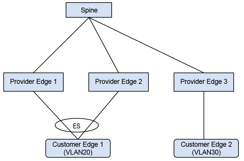
As part of an L2 EVPN service, E-Tree assigns the role of root or leaf to each attachment
circuit (AC). After assigning the role, E-Tree enforces the following rules:
Root ACs can communicate with Leaf ACs and other Root ACs.
Leaf ACs can only communicate with Root ACs, and traffic between Leaf ACs
blocked.
Configure the ACs at the VLAN level and enforce forwarding rules using a combination of
locally configured leaf VLANs for local hosts and asymmetric route targets for remote
hosts.
E-Tree supports the E-Tree extended community for EVPN Type-2 and Type-3 routes and
allows E-Tree operation with only a single route-target configured, a regular non-E-Tree
EVPN deployment. This support also allows EVPN MAC mobility to perform correctly in an
E-Tree environment. Only deployments that use VXLAN encapsulation support the E-Tree
extended community, and deployments using MPLS encapsulation must use asymmetric route
targets.
When implementing a single route-target E-Tree, EOS supports configurable handling of
remote leaf hosts in local leaf VLANs. By default, the local FDB for local leaf VLANs
does not install remote local leaf hosts. Instead, a per-VLAN configuration allows the
installation of explicit drop routes for remote leaf hosts, which removes unnecessary
BUM traffic at the cost of local FDB space.
E-Tree Extended Community
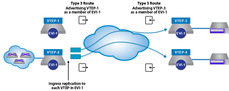
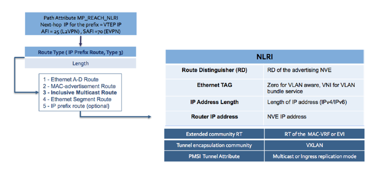
The E-Tree extended community automatically attaches to all EVPN type-2 and type-3 routes advertised by a device associated with a VLAN locally configured
as an E-Tree leaf AC. All type-2 routes that represent hosts learned on a leaf VLAN advertise the E-Tree extended community with a leaf flag set attached. All
type-3 routes that represent a VLAN configured as a leaf AC advertise the E-Tree extended community with the leaf flag set attached.
After receiving an EVPN type-2 route with the E-Tree extended community flag set
attached, a device checks the E-Tree role of the local VLAN to import the routes. If
configured as an E-Tree root AC, the local floodlist for the VLAN adds the remote
VTEP contained in the type-3 route. If the local VLAN has a configuration for an
E-Tree leaf, the local floodlist filters the remote VTEP contained in the type-3
route. Leaf VLANS contain only remote VTEPs in the floodlist associated with the
VLAN on the remote VTEP configured as an E-Tree root and prevents local leaf BUM
traffic from flooding to the remote leaf ACs.
EVPN Active/Active Multihoming
EOS only supports EVPN Active/Active Multihoming on root VLANs. Only the peer that
sees the host traffic learns the multihomed hosts if configured on leaf VLANs and
using asymmetric route-target E-Tree. Because type-2 routes from other peers in the
leaf VLANs do not import, an aliasing entry never installs for the hosts on the same
Ethernet segment learned on other peers.
In addition, if configured on leaf VLANS, when using single route target extended
community-based E-Tree, other peers in leaf VLANs import type-2 routes and
associated aliasing entries do not install on the local FDB and treat them as remote
leaf hosts.
In both cases, this leads to extra flooding as traffic destined for multihomed hosts
that land on peers have not locally learned to treat the host as BUM traffic and
floods.
In the following topology, we are connecting a Layer 2 site with a Layer 3 site using Layer
3 EVPN (type-5 route). The right side leaves are MLAG leaves and have SVI 10 in VRF-Blue. A
number of directly connected hosts are simulated behind the right side leaf. The left side
leaves are individual leaves that connect with a remote switch in
vrf VRF-Blue to learn Layer 3 routes using BGP. The left side
leaves are configured as two independent Layer 3 only VTEPs.
Figure 1. Layer 3 EVPN Configuration
To provide VXLAN routing and
bridging between the two MLAG domains, each leaf switch is EVPN peering
with the four spine switches via a loopback interface.
eBGP Underlay Configuration: Leaf-11
Underlay configuration is straightforward and all neighbors are eBGP. Since all
leaves share the same AS number, the allowas-in command was
added in the leaf.
switch(config)# interface ethernet 1/1
switch(config-if-Et1/1)# description Spine-1-et1/1
switch(config-if-Et1/1)# mtu 9214
switch(config-if-Et1/1)# no switchport
switch(config-if-Et1/1)# ip address 172.168.1.1/31
!
switch(config)# interface ethernet 8/1
switch(config-if-Et8/1)# description ck428-et8/1
switch(config-if-Et8/1)# speed forced 40gfull
switch(config-if-Et8/1)# no switchport
switch(config-if-Et8/1)# ip address 172.168.1.10/31
!
switch(config)# interface loopback 0
switch(config-if-Lo0)# ip address 1.1.1.11/32
!
switch(config)# ip prefix-list loopback
switch(config-ip-pfx-loopback)# seq 10 permit 1.1.1.0/24 ge 24
!
switch(config)# route-map loopback permit 10
switch(config-route-map-loopback)# match ip address prefix-list loopback
!
switch(config)# router bgp 200
switch(config-router-bgp)# neighbor SPINE peer group
switch(config-router-bgp)# neighbor SPINE remote-as 200
switch(config-router-bgp)# neighbor SPINE allowas-in 1
switch(config-router-bgp)# neighbor SPINE rib-in pre-policy retain
switch(config-router-bgp)# neighbor SPINE send-community
switch(config-router-bgp)# neighbor 172.168.1.0 peer group SPINE
switch(config-router-bgp)# neighbor 172.168.1.11 remote-as 200
switch(config-router-bgp)# redistribute connected route-map loopback
eBGP Underlay Configuration: Spine-1
switch(config)# interface ethernet 1/1
switch(config-if-Et1/1)# description leaf-11-et1
switch(config-if-Et1/1)# mtu 9214
switch(config-if-Et1/1)# no switchport
switch(config-if-Et1/1)# ip address 172.168.1.0/31
!
switch(config)# interface loopback 0
switch(config-if-Lo0)# ip address 1.1.1.1/32
!
switch(config)# ip prefix-list loopback
switch(config-ip-pfx-loopback)# seq 10 permit 1.1.1.0/24 ge 24
!
switch(config)# route-map loopback permit 10
switch(config-route-map-loopback)# match ip address prefix-list loopback
!
switch(config)# router bgp 200
switch(config-router-bgp)# neighbor 172.168.1.1 remote-as 200
switch(config-router-bgp)# redistribute connected route-map loopback
VRF Configuration: Leaf-11
VRF-Blue is configured on all the left leaves. The left leaves have pure Layer 3
interfaces and the right side has SVI 10.
Make sure all VTEPs have unique loopback0
addresses to represent unique VTEP identifiers. For every VNI that EVPN
receives, a dynamic VLAN is allocated, so it is a good practice to keep
the same VNI.
Leaf establishes the EVPN neighborship with all four spines for redundancy. EVPN
neighborship is on the loopback address and the multihop
keyword is used. Make sure to disable the IPv4 address family for EVPN neighbors.
Since the spine is acting like a route-reflector
for EVPN routes, make sure to configure the next-hop-unchanged.
By configuring VRF under router-bgp, you are advertising
routes from that VRF into EVPN using the RD/RT. The remote end can install the route by
importing the RT.
Leaf-11 has routes in VRF-Blue
learned through eBGP with the neighbor down south. Since the routes are already in BGP
VRF table, we do not want to configure the redistribute
command.
The following configuration example shows a deployment using both symmetric and asymmetric IRB,
with VLAN-based and VLAN-aware bundle services; and eBGP overlay and
underlay.
In the symmetric and asymmetric IRB configurations illustrated in the figures above, for
Tenant-A, four subnets are
stretched across the two MLAG domains with two subnets (VLAN
10, 10.10.10.0/24
and VLAN 11,
10.10.11.0/24) configured as a VLAN-based
service and two other subnets (VLAN
12,10.10.12.0/24 and
VLAN 13,
10.10.13.0/24) as a VLAN-aware
bundle service.
For Tenant-B, four subnets are stretched across the two MLAG domains
with two subnets (VLAN 210,
10.10.10.0/24 and VLAN
211,10.10.11.0/24) configured as a
VLAN-based service, and two other subnets (VLAN
212,10.10.12.0/24 and VLAN
213,10.10.13.0/24) as a VLAN-aware
bundle service.
In addition, each MLAG domain has a single local subnet (Rack-1 subnet
10.10.20.0/24 and
Rack-2 subnet
10.10.21.0/24) for the tenant. To
provide direct distributed routing, each leaf switch is configured with the
same virtual IP address for the four stretched subnets. The virtual IP
address is configured in both physical leaf switches of the relevant MLAG
domain for the local-only subnets.
For each MLAG domain, a logical VTEP is created with the same shared loopback address. For
Rack-1, the logical VTEP IP is
2.2.2.1 and for the Rack-2,
the logical VTEP IP is 2.2.2.2. Directly connected to each
leaf switch is a host, which is a member of one of the two IP subnets. To provide Layer
2 connectivity across the racks, VXLAN bridging is enabled by mapping VLAN to VNIs as
detailed in the diagram.
To provide IP connectivity across all subnets, both stretched and directly connected, an IP-VRF
is shared between the two MLAG domains for the tenant. This is used as a
transit network to announce and forward the locally attached subnets. Each
leaf switch is EVPN peering with the four spine switches via a loopback
interface on the leaf and again on the spine switches. To provide external
connectivity, Leaf-11 and
Leaf-12 are eBGP peering via the
tenants’ VRFs with the border routers. Both core routers are advertising
external prefixes for Internet and any remote site connectivity (default
route and IP prefixes from the other DC for the tenant). To provide
connectivity within the EVPN domain, the leaf switches
(Leaf-21 and
Leaf-22) re-advertise the prefixes
into the tenant’s VRF via a type-5 route advertisement, with a next-hop
equal to the advertising VTEP.
VLAN and Distributed IP Address Configuration:
Leaf-11 and Leaf-21
VLAN and interface configuration for VLAN 10 (virtual IP address
10.10.10.254) and VLAN 11
(virtual IP address 10.10.11.254), along with SVIs
12, 13, and
20, are similarly configured. To provide multi-tenancy, the
two tenant VLANs are placed in a dedicated VRF, named Tenant-A. A
further five tenant VLANs are configured and assigned to VRF
Tenant-B.
The other VLANs are for peering, MLAG,
and a unique VLAN SVI. These VLANs do not use virtual IP addresses.
The tenants’ stretched subnets (Tenant-A: VLANs
10,11,12,
and 13; Tenant-B: VLANs
210, 211,
211, 212, and
213) are mapped to unique overlay VXLAN VNIs. The tenants’
IP-VRF (Tenant-A and Tenant-B) is
associated with a VNI using the VXLAN vrf command under the VXLAN
interface. In the forwarding model for symmetric IRB, this VNI will be used as the transit
VNI for routing to subnets not locally configured on the VTEP.
As a standard MLAG configuration, both leaf switches in each MLAG domain share the same logical
VTEP IP address. Thus MLAG domain, Rack-1
(Leaf-11 + Leaf-12) has a shared
logical VTEP IP of 2.2.2.1 and Rack-2
(Leaf-21 + Leaf-22) has a shared
logical VTEP IP of 2.2.2.2.
Leaf-11 VLAN and Distributed IP Address Configuration
switch(config)# ip virtual-router mac-address 00:aa:aa:aa:aa:aa
!
switch(config)# vlan 10-11,20,210-211,220,111,2111
!
switch(config)# vlan 12-13
switch(config-vlan-12-13)# name VLAN-AWARE-BUNDLE-TENANT-A
!
switch(config)# vlan 212-213
switch(config-vlan-212-213)# name VLAN-AWARE-BUNDLE-TENANT-B
!
switch(config)# vrf instance tenant-a
!
switch(config)# vrf instance tenant-b
!
switch(config)# interface vlan 10
switch(config-if-Vl10)# mtu 9164
switch(config-if-Vl10)# vrf tenant-a
switch(config-if-Vl10)# ip address virtual 10.10.10.254/24
!
switch(config)# interface vlan 11
switch(config-if-Vl11)# mtu 9164
switch(config-if-Vl11)# vrf tenant-a
switch(config-if-Vl11)# ip address virtual 10.10.11.254/24
!
switch(config)# interface vlan 12
switch(config-if-Vl12)# mtu 9164
switch(config-if-Vl12)# vrf tenant-a
switch(config-if-Vl12)# ip address virtual 10.10.12.254/24
!
switch(config)# interface vlan 13
switch(config-if-Vl13)# mtu 9164
switch(config-if-Vl13)# vrf tenant-a
switch(config-if-Vl13)# ip address virtual 10.10.13.254/24
!
switch(config)# interface vlan 20
switch(config-if-Vl20)# mtu 9164
switch(config-if-Vl20)# vrf tenant-a
switch(config-if-Vl20)# ip address virtual 10.10.20.254/24
!
switch(config)# interface vlan 210
switch(config-if-Vl210)# mtu 9164
switch(config-if-Vl210)# vrf tenant-b
switch(config-if-Vl210)# ip address virtual 10.10.10.254/24
!
switch(config)# interface vlan 211
switch(config-if-Vl211)# mtu 9164
switch(config-if-Vl211)# vrf tenant-b
switch(config-if-Vl211)# ip address virtual 10.10.11.254/24
!
switch(config)# interface vlan 212
switch(config-if-Vl212)# mtu 9164
switch(config-if-Vl212)# vrf tenant-b
switch(config-if-Vl212)# ip address virtual 10.10.12.254/24
!
switch(config)# interface vlan 213
switch(config-if-Vl213)# mtu 9164
switch(config-if-Vl213)# vrf tenant-b
switch(config-if-Vl213)# ip address virtual 10.10.13.254/24
!
switch(config)# interface vlan 220
switch(config-if-Vl220)# mtu 9164
switch(config-if-Vl220)# vrf tenant-b
switch(config-if-Vl220)# ip address virtual 10.10.20.254/24
!
switch(config)# interface vlan 1111
switch(config-if-Vl1111)# description Unique-highest-IP-in-each-IP-Vrf
switch(config-if-Vl1111)# mtu 9164
switch(config-if-Vl1111)# vrf tenant-a
switch(config-if-Vl1111)# ip address 223.255.255.249/30
!
switch(config)# interface vlan 2111
switch(config-if-Vl2111)# description Unique-highest-IP-in-each-IP-Vrf
switch(config-if-Vl2111)# mtu 9164
switch(config-if-Vl2111)# vrf tenant-b
switch(config-if-Vl2111)# ip address 223.255.255.249/30
!
switch(config)# interface vlan 4093
switch(config-if-Vl4093)# ip address 172.168.11.1/30
Leaf-21 VLAN and Distributed IP Address Configuration
switch(config)# ip virtual-router mac-address 00:aa:aa:aa:aa:aa
!
switch(config)# vlan 10-11,20,210-211,220,111,2111
!
switch(config)# vlan 12-13
switch(config-vlan-12-13)# name VLAN-AWARE-BUNDLE-TENANT-A
!
switch(config)# vlan 212-213
switch(config-vlan-212-213)# name VLAN-AWARE-BUNDLE-TENANT-B
!
switch(config)# vrf instance tenant-a
!
switch(config)# vrf instance tenant-b
!
switch(config)# interface vlan 10
switch(config-if-Vl10)# mtu 9164
switch(config-if-Vl10)# vrf tenant-a
switch(config-if-Vl10)# ip address virtual 10.10.10.254/24
!
switch(config)# interface vlan 11
switch(config-if-Vl11)# mtu 9164
switch(config-if-Vl11)# vrf tenant-a
switch(config-if-Vl11)# ip address virtual 10.10.11.254/24
!
switch(config)# interface vlan 12
switch(config-if-Vl12)# mtu 9164
switch(config-if-Vl12)# vrf tenant-a
switch(config-if-Vl12)# ip address virtual 10.10.12.254/24
!
switch(config)# interface vlan 13
switch(config-if-Vl13)# mtu 9164
switch(config-if-Vl13)# vrf tenant-a
switch(config-if-Vl13)# ip address virtual 10.10.13.254/24
!
switch(config)# interface vlan 21
switch(config-if-Vl20)# mtu 9164
switch(config-if-Vl20)# vrf tenant-a
switch(config-if-Vl20)# ip address virtual 10.10.21.254/24
!
switch(config)# interface vlan 210
switch(config-if-Vl210)# mtu 9164
switch(config-if-Vl210)# vrf tenant-b
switch(config-if-Vl210)# ip address virtual 10.10.10.254/24
!
switch(config)# interface vlan 211
switch(config-if-Vl211)# mtu 9164
switch(config-if-Vl211)# vrf tenant-b
switch(config-if-Vl211)# ip address virtual 10.10.11.254/24
!
switch(config)# interface vlan 212
switch(config-if-Vl212)# mtu 9164
switch(config-if-Vl212)# vrf tenant-b
switch(config-if-Vl212)# ip address virtual 10.10.12.254/24
!
switch(config)# interface vlan 213
switch(config-if-Vl213)# mtu 9164
switch(config-if-Vl213)# vrf tenant-b
switch(config-if-Vl213)# ip address virtual 10.10.13.254/24
!
switch(config)# interface vlan 221
switch(config-if-Vl220)# mtu 9164
switch(config-if-Vl220)# vrf tenant-b
switch(config-if-Vl220)# ip address virtual 10.10.21.254/24
!
switch(config)# interface vlan 1111
switch(config-if-Vl1111)# description Unique-highest-IP-in-each-IP-Vrf
switch(config-if-Vl1111)# mtu 9164
switch(config-if-Vl1111)# vrf tenant-a
switch(config-if-Vl1111)# ip address 223.255.255.253/30
!
switch(config)# interface vlan 2111
switch(config-if-Vl2111)# description Unique-highest-IP-in-each-IP-Vrf
switch(config-if-Vl2111)# mtu 9164
switch(config-if-Vl2111)# vrf tenant-b
switch(config-if-Vl2111)# ip address 223.255.255.253/30
!
switch(config)# interface vlan 4093
switch(config-if-Vl4093)# ip address 172.168.11.1/30
VXLAN Interface Configuration: Leaf-11 and
Leaf-21
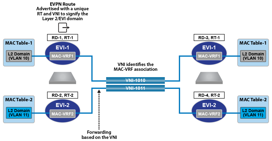
The tenants’ VLANs are mapped to unique overlay VXLAN VNIs. VLAN 10 is
mapped to VNI 1010 on both MLAG domains, and VLAN
11 is mapped to VNI 1011. As standard MLAG
configuration, both leaf switches in each MLAG domain share the same logical VTEP IP
address. Thus MLAG domain Rack-1
(Leaf-11 + Leaf-12) has a shared
logical VTEP IP of 2.2.2.1 and Rack-2
(Leaf-21 + Leaf-22) has a shared
logical VTEP IP of 2.2.2.2. Also configured is the VRF-to-VXLAN
mapping for Tenant-A.
Note: This configuration uses VXLAN routing. For single-chip T2 and TH platforms, recirculation must be enabled. For R-Series platforms, the following configuration commands must be added:
hardware tcam
system profile VXLAN-routing
Refer to diagrams for VLAN and SVI assignment to tenant;
Leaf-11 also has peering out to the border router in
addition to the connected SVIs.
eBGP Underlay Configuration on the Leaf Switches
The leaf switches for the underlay
network peer with each spine on the physical interface. For EVPN route
advertisement, the BGP EVPN session is between loopback addresses.
In this case, the underlay is all eBGP, and peering is on the physical interfaces. The MLAG
leaves also peer with each other in the underlay to retain BGP EVPN connectivity
(loopback reachability) in the unlikely case that all spine links are down. This is a
failover configuration that can be implemented if there is ever the chance a leaf could
be “core isolated.” The configuration can be viewed on each leaf using the command
show running-configuration section bgp.
The following examples show the underlay configuration on all four leaf switches, and also on two
of the spine switches as an example of the underlay configuration on the spine.
The configuration uses the following peer
groups:
SPINE configuration
inherited for underlay (eBGP) peering to the spines
SPINE_EVPN overlay
eBGP peering between spine and leaf, using loopbacks
The EVPN BGP configuration
on two of the spine switches is summarized below. Note that only the
EVPN BGP sessions are listed for the two spine switches: the BGP underlay
configuration is not included.
The MAC VRFs and IP VRF for
the tenants’ subnets are created in the BGP router context with unique
Route-Distinguishers (RD) and Route-Targets (RT) attached to each MAC-VRF
and IP-VRF. The RDs provide support for overlapping MAC and IP addresses
across tenants, while the RTs allow control of the routes imported and
exported between MAC VRFs.
To ensure all routes are correctly imported between VTEPs sharing the same Layer-2 domain, the
import and export RTs are equal across the two MLAG domains. The redistribute
learned statement under each MAC VRF ensures any locally learned MACs
in the VLAN are automatically announced as type-2 routes.
The IP VRF (Tenant-A) is created on all leaf switches which have
subnets attached to the tenant’s VRF with the same route target ensuring that routes are
correctly imported and exported between VTEPs in the VRF. On
Leaf-21 and Leaf-22, to import the
external routes an eBGP session with the BGP peering router is created under the IP VRF
(Tenant-A) context, and a peering from each to the other is
created on the overlay.
Note: All MAC VRFs are unique, and each has its own RT, matched by the other leaves in the DC. The
“tenants” as such are defined at layer 3 by assigning SVIs to the appropriate VRF. To view
this assignment, use the show ip route vrf <tenant>
connected command. Note below that VLANs
12-13 and
212-213 (shown in bold) are
configured as a bundle-aware EVPN service. Also note the peering from
Leaf-11 to the BGP border router in each tenant
VRF.
EVPN BGP Overlay Configuration for the Tenants’
MAC VRFs and IP VRF: Leaf-11
The EVPN BGP configuration on the spine switches is summarised in the following examples. Note
that only the EVPN BGP sessions are listed for two spine switches; the BGP underlay
configuration is not included.
In symmetric IRB, the host routes are generated by advertising type-2 routes with both the MAC
VRF VNI and the routing (or VRF) VNI. On Leaf-11, the
MAC VRFs for Tenant-A are left in their default
configuration (i.e., redistributing host routes). The following example shows the
configuration for the MAC VRF.
MAC VRF Configuration for Tenant-A: Leaf-11
The redistribute learned commands below cause type-2 routes
to be advertised with two labels: in VLAN 10,
1010 and 1000; in
VLAN 11, 1011 and 1000; in
VLAN 21, 1021 and
1000.
With this configuration, any locally learned MAC-IP binding on a leaf switch will be
advertised as a type-2 route with two labels. For example, on switches
Leaf-21 and Leaf-22, any
MAC-IP binding locally learned on subnets 10.10.10.0/24,
10.10.11.0/24, or
10.10.21.0/24 will be advertised as type-2 routes with two
labels (the MAC VRF of 1010, 1011,
or 1021 and the IP VRF of 1000) and
two route targets equal to the relevant MAC VRF for the host and IP VRF for the tenant
(1000:1000). The remote leaf switches
(Leaf-11 and Leaf-12), will
now learn the host route in the IP VRF.
In addition to advertising the type-2 routes with dual labels, the switch will still
advertise type-5 routes. This ensures connectivity to the remote subnet even when no
host on the subnet has been learned. With both a layer-2 route and layer-3 host route
for Server-3 learned on the MAC VRF(1010) and the IP VRF
(1000) on Leaf-11, traffic
ingressing on Leaf-11 from the local subnet
10.10.10.103 (i.e., VLAN 10)
will be VXLAN bridged based on the MAC VRF entry. Traffic ingressing from outside the
subnet (i.e., VLAN 11, 12,
13, or 20) will be routed to
the host via the IP VRF host route.
The VLAN-aware bundle VLAN type-2 routes
are advertised with the VNI ID within the update.
The type-5 routes are advertised with the IP VRF Route Distinguisher and the VNI
label, signifying that the forwarding path for the prefix would be the IP
VRF. The imported routes from the eBGP peering with the BGP border router in
Leaf-11 and
Leaf-12 are imported by both switches,
and redistributed via type-5 advertisements to
Leaf-21 and
Leaf-22.
Asymmetric IRB Configuration (Tenant-B)
In asymmetric IRB, the host routes are generated by advertising type-2 routes with just the MAC
VRF VNI. On leaf 11, the MAC VRFs for Tenant-B are configured
with no redistribute host route within the MAC VRF configuration. The following example
shows the configuration for the MAC VRF.
MAC VRF Configuration for Tenant-B: Leaf-11
The no redistribute host-route commands below cause type-2
routes to be advertised with a single label: in VLAN 210,
1110; in VLAN 211,
1211; in VLAN 220,
1220; and in the VLAN-aware bundle
(Tenant-B-VLAN-212-213), 1212
and 1213.
With this configuration, any locally learned MAC-IP binding on a leaf switch will be
advertised as a type-2 route with a single label. For example, on
Leaf-11 and Leaf-12, any
MAC-IP binding locally learned on subnets 10.10.10.0/24,
10.10.11.0/24, or
10.10.21.0/24 will be advertised as type-2 routes with a
single label, the MAC VRF (1210,
1211, 1220,
1212, 1213, or
21111). The IP VRF (1001)
still advertises the type-5 prefix routes. This ensures connectivity to the remote
subnet even when no host on the subnet has been learned.
The VLAN-aware bundle VLAN type-2 routes
are advertised with the VNI ID within the update.
EVPN MPLS Sample Configuration
This section describes configuring and verifying BGP VPN, which has steps similar to
the EVPN VXLAN demonstration. Here, we examine BGP EVPN layer 3 VPN over LDP, Segment
Routing (ISIS-SR), and BGP-SR transport LSPs. This highlights the difference between the
transport and the VPN overlay service.
Layer 3 VPN Over ISIS-SR
The following figures illustrate the overview of combined control and data planes.
Figure 5. Control Plane Tenant-A Over ISIS-SRFigure 6. Control Plane Tenant-B over ISIS-SRFigure 7. Control Plane and Forwarding Tenant-A Over ISIS-SR
The North Edge router has an eBGP peering session out to Leaf-11 and
Leaf-12 in DC1, while the South Edge
router has peerings to Leaf-11 andLeaf-12
in DC2. Tenant-a has few additional local interfaces used for
testing.
Example
The show ip route vrf tenant-a connected command displays the
interfaces assigned to the tenant-a of North Edge router.
switch# show ip route vrf tenant-a connected
VRF: tenant-a
Codes: C - connected, S - static, K - kernel,
O - OSPF, IA - OSPF inter area, E1 - OSPF external type 1,
E2 - OSPF external type 2, N1 - OSPF NSSA external type 1,
N2 - OSPF NSSA external type2, B I - iBGP, B E - eBGP,
R - RIP, I L1 - IS-IS level 1, I L2 - IS-IS level 2,
O3 - OSPFv3, A B - BGP Aggregate, A O - OSPF Summary,
NG - Nexthop Group Static Route, V - VXLAN Control Service,
DH - DHCP client installed default route, M - Martian,
DP - Dynamic Policy Route
C 192.168.168.8/30 is directly connected, Ethernet6/3.1
C 192.168.168.12/30 is directly connected, Ethernet6/2.1
Activating EVPN
In all scenarios, the EVPN must be activated under BGP and neighbors configured to exchange Layer
2 VPN/EVPN NLRI. The tenant’s VRF (tenant-a and tenant-b) is associated with a dynamically
assigned label by BGP.
An activated EVPN provides the following functionalities:
Enables the multi-agent routing protocol model, which is required for EVPN
support.
Sets the local autonomous system number to 64512 and configures IBGP neighbors that
are activated for the Layer 2 VPN/EVPN address family.
Sets the EVPN encapsulation type to MPLS.
Specifies that Loopback0 will be used as the next-hop for all advertised EVPN routes.
The underlay configuration must provide MPLS LSPs from remote PEs to this loopback
interface address.
Example
The service routing protocols model multi-agent command activates
EVPN on the north edge
router.
Distribution of layer 3 routes over BGP
is enabled by configuring one or more IP VRFs under the router bgp configuration
mode. Additionally, IP routing must be enabled in the VRF.
The VRF is assigned a unique Route-Distinguisher
(RD). The RD allows the PE to advertise EVPN routes for the same IP prefix
that have been exported by different VRFs. The NLRI RouteKey of a route
exported from the VRF’s IPv4 table into EVPN consists of both the RD
and the original IP prefix.
The Route-Target (RT) extended communities
for the VRF. The RTs are associated with all routes exported from the
VRF. Received EVPN type-5 routes carrying at least one RT matching the
VRFs configuration are imported into the VRF. The route target directives
are configured under the IPv4 or IPv6 address- family.
Example
The vrf tenant-a and vrf tenant-a
commands define overlay VRFs (tenant-a and
tenant-b) on the VTEP of North Edge router and enables IPv4
routing within
them.
Show commands are executed in the North
Edge router to view routes to the South Edge router. Execute the same
commands in the South Edge router to view vice-versa routes.
Examples
The show bgp evpn summary command displays the status of
EVPN peers in North Edge
router.
switch# show bgp evpn summary
BGP summary information for VRF default
Router identifier 1.1.1.111, local AS number 64512
Neighbor Status Codes: m - Under maintenance
Neighbor V AS MsgRcvd MsgSent InQ OutQ Up/Down State
PfxRcd PfxAcc
2.2.2.222 4 64512 195 127 0 0 01:13:31 Estab 78 78
The show bgp evpn route-type ip-prefix ipv4 next-hop 6.6.6.6
command displays all BGP EVPN ip prefix routes received from the South Edge router
(6.6.6.6). Not all are advertised via the RR
2.2.2.222.
Note: Each entry in the table represents a BGP path. The path specific information includes
Route-Distinguisher and IP prefix. Paths are either received from EVPN peers or
exported from local
VRFs.
switch# show bgp evpn route-type ip-prefix ipv4 next-hop 6.6.6.6
BGP routing table information for VRF default
Router identifier 1.1.1.111, local AS number 64512
Route status codes: s - suppressed, * - valid, > - active, # - not installed, E - ECMP head, e - ECMP
S - Stale, c - Contributing to ECMP, b - backup
% - Pending BGP convergence
Origin codes: i - IGP, e - EGP, ? - incomplete
AS Path Attributes: Or-ID - Originator ID, C-LST - Cluster List, LL Nexthop - Link Local Nexthop
Network Next Hop Metric LocPref Weight Path
* > RD: 6.6.6.6:64512 ip-prefix 0.0.0.0/0
6.6.6.6 0 100 0 ? Or-ID: 6.6.6.6 C-LST: 2.2.2.222
* > RD: 6.6.6.6:64513 ip-prefix 0.0.0.0/0
6.6.6.6 0 100 0 ? Or-ID: 6.6.6.6 C-LST: 2.2.2.222
* > RD: 6.6.6.6:64514 ip-prefix 10.255.255.0/30
6.6.6.6 - 100 0 65010 i Or-ID: 6.6.6.6 C-LST: 2.2.2.222
* > RD: 6.6.6.6:64512 ip-prefix 100.10.10.0/24
6.6.6.6 - 100 0 65006 i Or-ID: 6.6.6.6 C-LST: 2.2.2.222
* > RD: 6.6.6.6:64513 ip-prefix 100.10.10.0/24
6.6.6.6 - 100 0 65006 i Or-ID: 6.6.6.6 C-LST: 2.2.2.222
* > RD: 6.6.6.6:64512 ip-prefix 100.10.10.103/32
6.6.6.6 - 100 0 65006 65005 65006 i Or-ID: 6.6.6.6 C-LST: 2.2.2.222
* > RD: 6.6.6.6:64512 ip-prefix 100.10.10.104/32
6.6.6.6 - 100 0 65006 65005 65006 i Or-ID: 6.6.6.6 C-LST: 2.2.2.222
* > RD: 6.6.6.6:64512 ip-prefix 100.10.11.0/24
6.6.6.6 - 100 0 65006 i Or-ID: 6.6.6.6 C-LST: 2.2.2.222
* > RD: 6.6.6.6:64513 ip-prefix 100.10.11.0/24
6.6.6.6 - 100 0 65006 i Or-ID: 6.6.6.6 C-LST: 2.2.2.222
* > RD: 6.6.6.6:64512 ip-prefix 100.10.11.103/32
6.6.6.6 - 100 0 65006 65005 65006 i Or-ID: 6.6.6.6 C-LST: 2.2.2.222
* > RD: 6.6.6.6:64512 ip-prefix 100.10.11.104/32
6.6.6.6 - 100 0 65006 65005 65006 i Or-ID: 6.6.6.6 C-LST: 2.2.2.222
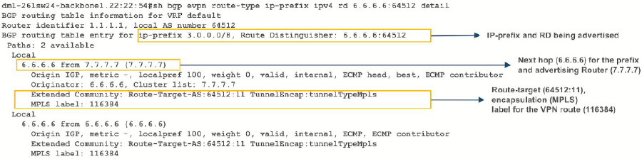
The show bgp evpn route-type ip-prefix 100.10.11.0/24 detail
command displays a detailed view of the IP prefix route for
100.10.11.0/24. The output again includes the RD and IP
prefix identifying the route. As seen above the route is received from the route
reflector, and the VPN label for tenant-a is
958810.
switch# show bgp evpn route-type ip-prefix 100.10.11.0/24 detail
BGP routing table information for VRF default
Router identifier 1.1.1.111, local AS number 64512
BGP routing table entry for ip-prefix 100.10.11.0/24, Route Distinguisher: 6.6.6.6:64512
Paths: 1 available
65006
6.6.6.6 from 2.2.2.222 (2.2.2.222)
Origin IGP, metric -, localpref 100, weight 0, valid, internal, best
Extended Community: Route-Target-AS:64512:11 TunnelEncap:tunnelTypeMpls
MPLS label: 958810
BGP routing table entry for ip-prefix 100.10.11.0/24, Route Distinguisher: 6.6.6.6:64513
Paths: 1 available
65006
6.6.6.6 from 2.2.2.222 (2.2.2.222)
Origin IGP, metric -, localpref 100, weight 0, valid, internal, best
Extended Community: Route-Target-AS:64513:11 TunnelEncap:tunnelTypeMpls
MPLS label: 953372
Note:Tenant-a
and tenant-b share the same route. Therefore, both route
with RD 6.6.6.6:64513 and RT
64513:11.
The show ip bgp vrf tenant-a command displays the BGP table
for VRF in tenant-a containing imported EVPN routes. Each entry in the table represent a
BGP path that is either locally redistributed / received into the VRF or imported from
the EVPN table.
switch# show ip bgp vrf tenant-a
BGP routing table information for VRF tenant-a
Router identifier 1.1.1.111, local AS number 64512
Route status codes: s - suppressed, * - valid, > - active, # - not installed, E - ECMP head, e - ECMP
S - Stale, c - Contributing to ECMP, b - backup, L - labeled-unicast
% - Pending BGP convergence
Origin codes: i - IGP, e - EGP, ? - incomplete
AS Path Attributes: Or-ID - Originator ID, C-LST - Cluster List, LL Nexthop - Link Local Nexthop
Network Next Hop Metric LocPref Weight Path
* > 0.0.0.0/0 6.6.6.6 0 100 0 ? Or-ID: 6.6.6.6 C-LST: 2.2.2.222
* >Ec 10.10.10.0/24 192.168.168.14 - 100 0 65002 i
* ec 10.10.10.0/24 192.168.168.10 - 100 0 65002 i
* >Ec 10.10.10.103/32 192.168.168.14 - 100 0 65002 i
* ec 10.10.10.103/32 192.168.168.10 - 100 0 65002 i
* >Ec 10.10.10.104/32 192.168.168.14 - 100 0 65002 i
* >Ec 10.10.44.1/32 192.168.168.14 - 100 0 65002 i
* ec 10.10.44.1/32 192.168.168.10 - 100 0 65002 i
* > 100.10.10.0/24 6.6.6.6 - 100 0 65006 i Or-ID: 6.6.6.6 C-LST: 2.2.2.222
* > 100.10.10.103/32 6.6.6.6 - 100 0 65006 65005 65006 i Or-ID: 6.6.6.6
C-LST: 2.2.2.222
* > 100.10.10.104/32 6.6.6.6 - 100 0 65006 65005 65006 i Or-ID: 6.6.6.6
C-LST: 2.2.2.222
C-LST: 2.2.2.222
* > 100.10.21.102/32 6.6.6.6 - 100 0 65006 65005 65006 i Or-ID: 6.6.6.6
C-LST: 2.2.2.222
* > 100.10.30.0/24 6.6.6.6 - 100 0 65006 i Or-ID: 6.6.6.6 C-LST: 2.2.2.222
* > 100.10.32.0/24 6.6.6.6 - 100 0 65006 i Or-ID: 6.6.6.6 C-LST: 2.2.2.222
* > 192.168.168.0/30 6.6.6.6 - 100 0 i Or-ID: 6.6.6.6 C-LST: 2.2.2.222
* > 192.168.168.4/30 6.6.6.6 - 100 0 i Or-ID: 6.6.6.6 C-LST: 2.2.2.222
* > 192.168.168.8/30 - - - 0 i
* Ec 192.168.168.8/30 192.168.168.14 - 100 0 65002 i
* ec 192.168.168.8/30 192.168.168.10 - 100 0 65002 i
* > 192.168.168.12/30 - - - 0 i
* Ec 192.168.168.12/30 192.168.168.14 - 100 0 65002 i
* ec 192.168.168.12/30 192.168.168.10 - 100 0 65002 i
* > 223.255.254.248/30 6.6.6.6 - 100 0 65006 i Or-ID: 6.6.6.6 C-LST: 2.2.2.222
* > 223.255.254.252/30 6.6.6.6 - 100 0 65006 65005 65006 i Or-ID: 6.6.6.6
C-LST: 2.2.2.222
* >Ec 223.255.255.248/30 192.168.168.14 - 100 0 65002 i
* ec 223.255.255.248/30 192.168.168.10 - 100 0 65002 i
* >Ec 223.255.255.252/30 192.168.168.14 - 100 0 65002 i
* ec 223.255.255.252/30 192.168.168.10 - 100 0 65002 i
Note: EVPN routes are received from router
2.2.2.222 C-List (cluster list - basically identifying
this route as from a route-reflector) with originating router being
6.6.6.6.
The show ip route vrf tenant-b command displays the BGP
table for VRF in tenant-b containing imported EVPN
routes.
switch# show ip route vrf tenant-b
VRF: tenant-b
Codes: C - connected, S - static, K - kernel,
O - OSPF, IA - OSPF inter area, E1 - OSPF external type 1,
E2 - OSPF external type 2, N1 - OSPF NSSA external type 1,
N2 - OSPF NSSA external type2, B I - iBGP, B E - eBGP,
R - RIP, I L1 - IS-IS level 1, I L2 - IS-IS level 2,
O3 - OSPFv3, A B - BGP Aggregate, A O - OSPF Summary,
NG - Nexthop Group Static Route, V - VXLAN Control Service,
DH - DHCP client installed default route, M - Martian,
DP - Dynamic Policy Route
Gateway of last resort:
B I 0.0.0.0/0 [200/0] via 6.6.6.6/32, IS-IS SR tunnel index 6, label 953372
via 192.168.58.12, Ethernet1/1, label 408006
via 192.168.59.12, Ethernet2/1, label 408006
B E 10.10.10.0/24 [200/0] via 192.168.168.22, Ethernet6/2.2
via 192.168.168.20, Ethernet6/3.2
B E 10.10.21.0/24 [200/0] via 192.168.168.22, Ethernet6/2.2
via 192.168.168.20, Ethernet6/3.2
B I 100.10.10.0/24 [200/0] via 6.6.6.6/32, IS-IS SR tunnel index 6, label 953372
via 192.168.58.12, Ethernet1/1, label 408006
via 192.168.59.12, Ethernet2/1, label 408006
C 192.168.168.20/31 is directly connected, Ethernet6/3.2
C 192.168.168.22/31 is directly connected, Ethernet6/2.2
B I 223.255.254.248/30 [200/0] via 6.6.6.6/32, IS-IS SR tunnel index 6, label 953372
via 192.168.58.12, Ethernet1/1, label 408006
via 192.168.59.12, Ethernet2/1, label 408006
B I 223.255.254.252/30 [200/0] via 6.6.6.6/32, IS-IS SR tunnel index 6, label 953372
via 192.168.58.12, Ethernet1/1, label 408006
via 192.168.59.12, Ethernet2/1, label 408006
B E 223.255.255.248/30 [200/0] via 192.168.168.22, Ethernet6/2.2
via 192.168.168.20, Ethernet6/3.2
B E 223.255.255.252/30 [200/0] via 192.168.168.22, Ethernet6/2.2
via 192.168.168.20, Ethernet6/3.2
Note: If
we look at the routes in the VRF for tenant-b, we see that the VPN label has now
changed, whilst the transport label for NH 6.6.6.6 is the
same. The only difference seen in tenant-b, aside from the
different VPN label, is that there are no host-routes in
tenant-b because within each DC
tenant-b is running in asymmetric mode, therefore no
host routes are generated/installed in the IP VRF.
Layer 3 EVPN Over LDP
The following figures illustrate an overview of the combined control and data planes.
Figure 8. Control Plane Tenant-A Over LDPFigure 9. Control Plane Tenant-B over LDPFigure 10. Control Plane & Forwarding Tenant-A Over LDP
To switch to using the MPLS LDP transport, change the next-hop advertised for EVPN
routes. As illustrated above, the next hop needs to be set to loopback
200 to use the LDP LSP.
This is achieved by configuring the next-hop for EVPN routes on both North Edge and South
Edge routes. The output again includes the RD and IP prefixes identifying
the route. As seen in the output, we now have the NH set to
6.6.6.200 for
tenant-a and
tenant-b.
Once this is configured, we can check the
BGP updates and the routes in the VRF.
switch# show bgp evpn route-type ip-prefix 100.10.11.0/24 detail
BGP routing table information for VRF default
Router identifier 1.1.1.111, local AS number 64512
BGP routing table entry for ip-prefix 100.10.11.0/24, Route Distinguisher: 6.6.6.6:64512
Paths: 1 available
65006
6.6.6.200 from 2.2.2.222 (2.2.2.222)
Origin IGP, metric -, localpref 100, weight 0, valid, internal, best
Extended Community: Route-Target-AS:64512:11 TunnelEncap:tunnelTypeMpls
MPLS label: 958810
BGP routing table entry for ip-prefix 100.10.11.0/24, Route Distinguisher: 6.6.6.6:64513
Paths: 1 available
65006
6.6.6.200 from 2.2.2.222 (2.2.2.222)
Origin IGP, metric -, localpref 100, weight 0, valid, internal, best
Extended Community: Route-Target-AS:64513:11 TunnelEncap:tunnelTypeMpls
MPLS label: 953372
Note: We have the same route in tenant-a and tenant-b in DC2. Therefore, VPN label
has not changed in the two other routes with RD
6.6.6.6:64513 and RT
64513:11, reinforcing the fact that the BGP
VPN label is orthogonal to the transport label.
Finally, look at the routes in the VRF tenant-a.
switch# show ip route vrf tenant-a
VRF: tenant-a
Codes: C - connected, S - static, K - kernel,
O - OSPF, IA - OSPF inter area, E1 - OSPF external type 1,
E2 - OSPF external type 2, N1 - OSPF NSSA external type 1,
N2 - OSPF NSSA external type2, B I - iBGP, B E - eBGP,
R - RIP, I L1 - IS-IS ----level 1, I L2 - IS-IS level 2,
O3 - OSPFv3, A B - BGP Aggregate, A O - OSPF Summary,
NG - Nexthop Group Static Route, V - VXLAN Control Service,
DH - DHCP client installed default route, M - Martian,
DP - Dynamic Policy Route
Gateway of last resort:
B I 0.0.0.0/0 [200/0] via 6.6.6.200/32, LDP tunnel index 1, label 958810
via 192.168.58.12, Ethernet1/1, label 904097
via 192.168.59.12, Ethernet2/1, label 904098
B E 10.10.10.103/32 [200/0] via 192.168.168.14, Ethernet6/2.1
via 192.168.168.10, Ethernet6/3.1
B E 10.10.10.104/32 [200/0] via 192.168.168.14, Ethernet6/2.1
via 192.168.168.10, Ethernet6/3.1
B I 100.10.10.103/32 [200/0] via 6.6.6.200/32, LDP tunnel index 1, label 958810
via 192.168.58.12, Ethernet1/1, label 904097
via 192.168.59.12, Ethernet2/1, label 904098
B I 192.168.168.4/30 [200/0] via 6.6.6.200/32, LDP tunnel index 1, label 958810
via 192.168.58.12, Ethernet1/1, label 904097
via 192.168.59.12, Ethernet2/1, label 904098
C 192.168.168.8/30 is directly connected, Ethernet6/3.1
C 192.168.168.12/30 is directly connected, Ethernet6/2.1
B I 223.255.254.248/30 [200/0] via 6.6.6.200/32, LDP tunnel index 1, label 958810
via 192.168.58.12, Ethernet1/1, label 904097
via 192.168.59.12, Ethernet2/1, label 904098
B I 223.255.254.252/30 [200/0] via 6.6.6.200/32, LDP tunnel index 1, label 958810
via 192.168.58.12, Ethernet1/1, label 904097
via 192.168.59.12, Ethernet2/1, label 904098
B E 223.255.255.248/30 [200/0] via 192.168.168.14, Ethernet6/2.1
via 192.168.168.10, Ethernet6/3.1
B E 223.255.255.252/30 [200/0] via 192.168.168.14, Ethernet6/2.1
via 192.168.168.10, Ethernet6/3.1
Note: As can be seen from the highlighted route above the label stack, the route has
the same VPN route 958810, but the transport
labels are now 904097 and
904098 on top (this is the ECMP
label path to reach NH 6.6.6.200).
As a comparison, let us look at the routes for tenant-b.
switch# show ip route vrf tenant-b
VRF: tenant-b
Codes: C - connected, S - static, K - kernel,
O - OSPF, IA - OSPF inter area, E1 - OSPF external type 1,
E2 - OSPF external type 2, N1 - OSPF NSSA external type 1,
N2 - OSPF NSSA external type2, B I - iBGP, B E - eBGP,
R - RIP, I L1 - IS-IS level 1, I L2 - IS-IS level 2,
O3 - OSPFv3, A B - BGP Aggregate, A O - OSPF Summary,
NG - Nexthop Group Static Route, V - VXLAN Control Service,
DH - DHCP client installed default route, M - Martian,
DP - Dynamic Policy Route
Gateway of last resort:
B I 0.0.0.0/0 [200/0] via 6.6.6.200/32, LDP tunnel index 1, label 953372
via 192.168.58.12, Ethernet1/1, label 904097
via 192.168.59.12, Ethernet2/1, label 904098
B E 10.10.10.0/24 [200/0] via 192.168.168.22, Ethernet6/2.2
via 192.168.168.20, Ethernet6/3.2
B I 100.10.10.0/24 [200/0] via 6.6.6.200/32, LDP tunnel index 1, label 953372
via 192.168.58.12, Ethernet1/1, label 904097
via 192.168.59.12, Ethernet2/1, label 904098
B I 192.168.168.18/31 [200/0] via 6.6.6.200/32, LDP tunnel index 1, label 953372
via 192.168.58.12, Ethernet1/1, label 904097
via 192.168.59.12, Ethernet2/1, label 904098
C 192.168.168.20/31 is directly connected, Ethernet6/3.2
C 192.168.168.22/31 is directly connected, Ethernet6/2.2
B I 223.255.254.248/30 [200/0] via 6.6.6.200/32, LDP tunnel index 1, label 953372
via 192.168.58.12, Ethernet1/1, label 904097
via 192.168.59.12, Ethernet2/1, label 904098
B I 223.255.254.252/30 [200/0] via 6.6.6.200/32, LDP tunnel index 1, label 953372
via 192.168.58.12, Ethernet1/1, label 904097
via 192.168.59.12, Ethernet2/1, label 904098
B E 223.255.255.248/30 [200/0] via 192.168.168.22, Ethernet6/2.2
via 192.168.168.20, Ethernet6/3.2
B E 223.255.255.252/30 [200/0] via 192.168.168.22, Ethernet6/2.2
Note: The only difference apart from the missing host routes (no host-route inject
for this tenant), is the VPN label.
Layer 3 EVPN Over BGP-SR
The following figures illustrate an overview of the combined control and data
planes.
Figure 11. Control Plane Tenant-A Over BGP-SRFigure 12. Control Plane Tenant-B Over BGP-SRFigure 13. Control Plane and Forwarding Tenant-A Over BGP-SR
To switch to using the MPLS BGP-SR transport, we need to change the next-hop advertised
for the EVPN routes. As shown in Control Plane
tenant-b Over BGP-SR, the next hop
needs to be set to loopback 1 for using the BGP-SR
LSP, by configuring the next-hop for the EVPN routes.
Once the next-hop for the EVPN routes are configured, we can check the BGP updates and
the routes in the VRF. The output again includes the RD and IP prefix
identifying the route. As seen in the output, we now have the NH set to
6.6.6.66 for
tenant-a and
tenant-b.
switch# show bgp evpn route-type ip-prefix 100.10.11.0/24 detail
north-edge(config-if-Et2/1)#show bgp evpn route-type ip-prefix 100.10.11.0/24 detail
BGP routing table information for VRF default
Router identifier 1.1.1.111, local AS number 64512
BGP routing table entry for ip-prefix 100.10.11.0/24, Route Distinguisher: 6.6.6.6:64512
Paths: 1 available
65006
6.6.6.66 from 2.2.2.222 (2.2.2.222)
Origin IGP, metric -, localpref 100, weight 0, valid, internal, best
Extended Community: Route-Target-AS:64512:11 TunnelEncap:tunnelTypeMpls
MPLS label: 958810
BGP routing table entry for ip-prefix 100.10.11.0/24, Route Distinguisher: 6.6.6.6:64513
Paths: 1 available
65006
6.6.6.66 from 2.2.2.222 (2.2.2.222)
Origin IGP, metric -, localpref 100, weight 0, valid, internal, best
Extended Community: Route-Target-AS:64513:11 TunnelEncap:tunnelTypeMpls
MPLS label: 953372
Note: Again, we have the same route in tenant-a and tenant-b in DC2.
Therefore, the two other routes with RD
6.6.6.6:64513 and RT
64513:11. The VPN label has not
changed, reinforcing the fact that the BGP VPN label is orthogonal
to the transport label.
Finally, let us look at the routes in the VRF tenant-a.
switch# show ip route vrf tenant-a
VRF: tenant-a
Codes: C - connected, S - static, K - kernel,
O - OSPF, IA - OSPF inter area, E1 - OSPF external type 1,
E2 - OSPF external type 2, N1 - OSPF NSSA external type 1,
N2 - OSPF NSSA external type2, B I - iBGP, B E - eBGP,
R - RIP, I L1 - IS-IS level 1, I L2 - IS-IS level 2,
O3 - OSPFv3, A B - BGP Aggregate, A O - OSPF Summary,
NG - Nexthop Group Static Route, V - VXLAN Control Service,
DH - DHCP client installed default route, M - Martian,
DP - Dynamic Policy Route
Gateway of last resort:
B I 0.0.0.0/0 [200/0] via 6.6.6.66/32, BGP LU tunnel index 8, label 958810
via 192.168.58.12, Ethernet1/1, label 200066
via 192.168.59.12, Ethernet2/1, label 200066
B E 10.10.10.103/32 [200/0] via 192.168.168.14, Ethernet6/2.1
via 192.168.168.10, Ethernet6/3.1
B E 10.10.10.104/32 [200/0] via 192.168.168.14, Ethernet6/2.1
via 192.168.168.10, Ethernet6/3.1
B I 100.10.10.103/32 [200/0] via 6.6.6.66/32, BGP LU tunnel index 8, label 958810
via 192.168.58.12, Ethernet1/1, label 200066
via 192.168.59.12, Ethernet2/1, label 200066
B I 192.168.168.4/30 [200/0] via 6.6.6.66/32, BGP LU tunnel index 8, label 958810
via 192.168.58.12, Ethernet1/1, label 200066
via 192.168.59.12, Ethernet2/1, label 200066
C 192.168.168.8/30 is directly connected, Ethernet6/3.1
C 192.168.168.12/30 is directly connected, Ethernet6/2.1
B I 223.255.254.248/30 [200/0] via 6.6.6.66/32, BGP LU tunnel index 8, label 958810
via 192.168.58.12, Ethernet1/1, label 200066
via 192.168.59.12, Ethernet2/1, label 200066
B I 223.255.254.252/30 [200/0] via 6.6.6.66/32, BGP LU tunnel index 8, label 958810
via 192.168.58.12, Ethernet1/1, label 200066
via 192.168.59.12, Ethernet2/1, label 200066
B E 223.255.255.248/30 [200/0] via 192.168.168.14, Ethernet6/2.1
via 192.168.168.10, Ethernet6/3.1
B E 223.255.255.252/30 [200/0] via 192.168.168.14, Ethernet6/2.1
via 192.168.168.10, Ethernet6/3.1
As can be seen from the highlighted route above the label stack, the route are the
transport labels 958810 and
200066 on top (this is the ECMP
label path to reach NH 6.6.6.66), with the
tenant-a VPN label
958810 next in the stack,
identifying the route as belonging to
tenant-a.
As a comparison, look at the routes for tenant-b. As seen in
the output, the VPN label assigned to tenant-b is
953372.
switch# show bgp evpn route-type ip-prefix 100.10.11.0/24 detail
BGP routing table information for VRF default
Router identifier 1.1.1.111, local AS number 64512
BGP routing table entry for ip-prefix 100.10.11.0/24, Route Distinguisher: 6.6.6.6:64512
Paths: 1 available
65006
6.6.6.66 from 2.2.2.222 (2.2.2.222)
Origin IGP, metric -, localpref 100, weight 0, valid, internal, best
Extended Community: Route-Target-AS:64512:11 TunnelEncap:tunnelTypeMpls
MPLS label: 958810
BGP routing table entry for ip-prefix 100.10.11.0/24, Route Distinguisher: 6.6.6.6:64513
Paths: 1 available
65006
6.6.6.66 from 2.2.2.222 (2.2.2.222)
Origin IGP, metric -, localpref 100, weight 0, valid, internal, best
Extended Community: Route-Target-AS:64513:11 TunnelEncap:tunnelTypeMpls
MPLS label: 953372
north-edge#
If we now look at the routes in the VRF for tenant-b, we see
that the VPN label has now changed, while the transport label (for
NH 6.6.6.66 is the same). The only
difference seen in tenant-b, aside from the
different VPN label, is that there are no host-routes in
tenant-b because within each DC
tenant-b is running in asymmetric
mode; therefore, no host routes are generated/installed in the IP VRF.
switch# show ip route vrf tenant-b
VRF: tenant-b
Codes: C - connected, S - static, K - kernel,
O - OSPF, IA - OSPF inter area, E1 - OSPF external type 1,
E2 - OSPF external type 2, N1 - OSPF NSSA external type 1,
N2 - OSPF NSSA external type2, B I - iBGP, B E - eBGP,
R - RIP, I L1 - IS-IS level 1, I L2 - IS-IS level 2,
O3 - OSPFv3, A B - BGP Aggregate, A O - OSPF Summary,
NG - Nexthop Group Static Route, V - VXLAN Control Service,
DH - DHCP client installed default route, M - Martian,
DP - Dynamic Policy Route
Gateway of last resort:
B I 0.0.0.0/0 [200/0] via 6.6.6.66/32, BGP LU tunnel index 8, label 953372
via 192.168.58.12, Ethernet1/1, label 200066
via 192.168.59.12, Ethernet2/1, label 200066
B E 10.10.10.0/24 [200/0] via 192.168.168.22, Ethernet6/2.2
via 192.168.168.20, Ethernet6/3.2
B E 10.10.21.0/24 [200/0] via 192.168.168.22, Ethernet6/2.2
via 192.168.168.20, Ethernet6/3.2
B I 100.10.10.0/24 [200/0] via 6.6.6.66/32, BGP LU tunnel index 8, label 953372
via 192.168.58.12, Ethernet1/1, label 200066
via 192.168.59.12, Ethernet2/1, label 200066
B I 192.168.168.18/31 [200/0] via 6.6.6.66/32, BGP LU tunnel index 8, label 953372
via 192.168.58.12, Ethernet1/1, label 200066
via 192.168.59.12, Ethernet2/1, label 200066
C 192.168.168.20/31 is directly connected, Ethernet6/3.2
C 192.168.168.22/31 is directly connected, Ethernet6/2.2
B I 223.255.254.248/30 [200/0] via 6.6.6.66/32, BGP LU tunnel index 8, label 953372
via 192.168.58.12, Ethernet1/1, label 200066
via 192.168.59.12, Ethernet2/1, label 200066
B I 223.255.254.252/30 [200/0] via 6.6.6.66/32, BGP LU tunnel index 8, label 953372
via 192.168.58.12, Ethernet1/1, label 200066
via 192.168.59.12, Ethernet2/1, label 200066
B E 223.255.255.248/30 [200/0] via 192.168.168.22, Ethernet6/2.2
via 192.168.168.20, Ethernet6/3.2
B E 223.255.255.252/30 [200/0] via 192.168.168.22, Ethernet6/2.2
via 192.168.168.20, Ethernet6/3.2
EVPN VXLAN IPv6 Overlay
Beginning with EOS Release 4.22.0F, the EVPN VXLAN L3 Gateway using EVPN IRB
supports routing traffic from one IPv6 host to another IPv6 host on a stretched VXLAN
VLAN.
IP VPNs Sample Configuration
Here, we examine BGP EVPN layer
3 VPN over an LDP, ISIS-SR, and BGP-SR transport LSPs. This highlights
the separation between the transport and the VPN overlay service.
The following figures illustrate the sample VPN Physical Topology.
The following figure illustrates an overview of the combined control and data planes.
Figure 16. IPv4 VPN and IPv6 VPN Over ISIS-SR MPLS
The next two figures illustrate the forwarding path and control plane for both IP traffic over
ISIS MPLS segment routing.
Figure 17. IPv4 VPN Forwarding Over ISIS-SR MPLSFigure 18. IPv6 VPN Forwarding Over ISIS-SR MPLS
View IPv4 and IPv6 Routes in the VRF
North Edge and South Edge routers have an eBGP peering session out to the CE; and learning routes
from CE and remote PE.
The show ip route vrf tenant-d command displays
IPv4 Routes in the VRF of North Edge.
switch# show ip route vrf tenant-d
VRF: tenant-d
Codes: C - connected, S - static, K - kernel,
O - OSPF, IA - OSPF inter area, E1 - OSPF external type 1,
E2 - OSPF external type 2, N1 - OSPF NSSA external type 1,
N2 - OSPF NSSA external type2, B I - iBGP, B E - eBGP,
R - RIP, I L1 - IS-IS level 1, I L2 - IS-IS level 2,
O3 - OSPFv3, A B - BGP Aggregate, A O - OSPF Summary,
NG - Nexthop Group Static Route, V - VXLAN Control Service,
DH - DHCP client installed default route, M - Martian,
DP - Dynamic Policy Route
Gateway of last resort is not set
B I 10.255.255.0/30 [200/0] via 6.6.6.6/32, IS-IS SR tunnel index 6, label 967920
via 192.168.58.12, Ethernet1/1, label 408006
C 10.255.255.4/30 is directly connected, Ethernet6/1.120
B E 201.0.0.0/24 [200/0] via 10.255.255.6, Ethernet6/1.120
B I 206.0.0.0/24 [200/0] via 6.6.6.6/32, IS-IS SR tunnel index 6, label 967920
via 192.168.58.12, Ethernet1/1, label 408006
The show ip route vrf tenant-d command displays
IPv4 Routes in the VRF of South Edge.
switch# show ip route vrf tenant-d
VRF: tenant-d
Codes: C - connected, S - static, K - kernel,
O - OSPF, IA - OSPF inter area, E1 - OSPF external type 1,
E2 - OSPF external type 2, N1 - OSPF NSSA external type 1,
N2 - OSPF NSSA external type2, B I - iBGP, B E - eBGP,
R - RIP, I L1 - IS-IS level 1, I L2 - IS-IS level 2,
O3 - OSPFv3, A B - BGP Aggregate, A O - OSPF Summary,
NG - Nexthop Group Static Route, V - VXLAN Control Service,
DH - DHCP client installed default route, M - Martian,
DP - Dynamic Policy Route
Gateway of last resort is not set
C 10.255.255.0/30 is directly connected, Ethernet6/1.620
B I 10.255.255.4/30 [200/0] via 1.1.1.111/32, IS-IS SR tunnel index 5, label 951536
via 192.168.68.11, Ethernet2/1, label 408001
B I 201.0.0.0/24 [200/0] via 1.1.1.111/32, IS-IS SR tunnel index 5, label 951536
via 192.168.68.11, Ethernet2/1, label 408001
B E 206.0.0.0/24 [200/0] via 10.255.255.2, Ethernet6/1.620
The show ipv6 route vrf tenant-d command displays
IPv6 Routes in the VRF of North Edge.
switch# show ipv6 route vrf tenant-d
VRF: tenant-d
Displaying 4 of 7 IPv6 routing table entries
Codes: C - connected, S - static, K - kernel, O3 - OSPFv3, B - BGP, R - RIP, A B - BGP Aggregate, I L1 -
IS-IS level 1, I L2 - IS-IS level 2, DH - DHCP, NG - Nexthop Group Static Route, M - Martian, DP - Dynamic
Policy Route
B 2010::/126 [200/0]
via 6.6.6.6/32, IS-IS SR tunnel index 6, label 965242
via 192.168.58.12, Ethernet1/1, label 408006
C 2010::4/126 [0/0]
via Ethernet6/1.120, directly connected
B 2201::/64 [200/0]
via 2010::6, Ethernet6/1.120
B 2206::/64 [200/0]
via 6.6.6.6/32, IS-IS SR tunnel index 6, label 965242
via 192.168.58.12, Ethernet1/1, label 408006
The show ipv6 route vrf tenant-d command displays
IPv6 Routes in the VRF of South Edge.
switch# show ipv6 route vrf tenant-d
VRF: tenant-d
Displaying 4 of 7 IPv6 routing table entries
Codes: C - connected, S - static, K - kernel, O3 - OSPFv3, B - BGP, R - RIP, A B - BGP Aggregate, I L1 -
IS-IS level 1, I L2 - IS-IS level 2, DH - DHCP, NG - Nexthop Group Static Route, M - Martian, DP - Dynamic
Policy Route
C 2010::/126 [0/0]
via Ethernet6/1.620, directly connected
B 2010::4/126 [200/0]
via 1.1.1.111/32, IS-IS SR tunnel index 5, label 948858
via 192.168.68.11, Ethernet2/1, label 408001
B 2201::/64 [200/0]
via 1.1.1.111/32, IS-IS SR tunnel index 5, label 948858
via 192.168.68.11, Ethernet2/1, label 408001
B 2206::/64 [200/0]
via 2010::2, Ethernet6/1.620
Activating IP VPN
In all scenarios, the IP VPN must be activated
under BGP and neighbors configured to exchange the IP VPN NLRIs.The tenant’s
VRF (tenant-d) is associated with a dynamically assigned label by BGP.
It enables the multi-agent routing protocol model, which is required for BGP VPN
support.
It sets the local autonomous system number to 64512 and
configured the route-reflector for both IPv4 VPN and IPv6 VPN capabilities.
It sets the IP VPN encapsulation type to MPLS (default).
It specifies that Loopback0 will be used as the next-hop for
all advertised VPN routes. The underlay configuration must provide MPLS LSPs from remote
PEs to this loopback interface address.
Layer 3 Overlay Configuration
Distribution of Layer 3 routes over BGP
is enabled by configuring one or more IP VRFs under the router bgp configuration
mode. Additionally, either IPv4 or IPv6 routing must be enabled in the
VRF.
These IP VRF configurations provide the following functionalities:
It defines overlay VRFs (tenant-d) on the PE and enables IP unicast routing.
The VRF is assigned a unique Route-Distinguisher (RD). The RD allows the PE to
advertise VPN routes for the same IP prefix that have been exported by different VRFs.
The NLRI RouteKey of a route exported from the VRFs IPv4 table into VPN consists of both
the RD and the original IP prefix.
The Route-Target (RT) extended communities for the VRF. The RTs are associated with
all routes exported from the VRF. Received VPN routes carrying at least one RT matching
the VRFs configuration are imported into the VRF.
Verifying IP VPNs over ISIS-SR
The show bgp vpn-ipv4 summary command displays the
status of the VPN IP peers in the North Edge router with the BGP VPN enabled.
switch# show bgp vpn-ipv4 summary
BGP summary information for VRF default
Router identifier 1.1.1.111, local AS number 64512
Neighbor Status Codes: m - Under maintenance
Neighbor V AS MsgRcvd MsgSent InQ OutQ Up/Down State
PfxRcd PfxAcc
2.2.2.222 4 64512 172 45 0 0 00:17:16 Estab 2 2
north-edge# show bgp vpn-ipv6 summary
BGP summary information for VRF default
Router identifier 1.1.1.111, local AS number 64512
Neighbor Status Codes: m - Under maintenance
Neighbor V AS MsgRcvd MsgSent InQ OutQ Up/Down State
PfxRcd PfxAcc
2.2.2.222 4 64512 172 45 0 0 00:17:20 Estab 2 2
The show bgp vpn-ipv4 command displays routes sent
and received through IP VPN.
switch# show bgp vpn-ipv4
BGP routing table information for VRF default
Router identifier 1.1.1.111, local AS number 64512
Route status codes: s - suppressed, * - valid, > - active, # - not installed, E - ECMP head, e - ECMP
S - Stale, c - Contributing to ECMP, b - backup
% - Pending BGP convergence
Origin codes: i - IGP, e - EGP, ? - incomplete
AS Path Attributes: Or-ID - Originator ID, C-LST - Cluster List, LL Nexthop - Link Local Nexthop
Network Next Hop Metric LocPref Weight Path
* > RD: 6.6.6.6:64514 IPv4 prefix 10.255.255.0/30
6.6.6.6 - 100 0 65010 i Or-ID: 6.6.6.6 C-LST: 2.2.2.222
* > RD: 1.1.1.1:64514 IPv4 prefix 10.255.255.4/30
- - 100 0 65011 i
* > RD: 1.1.1.1:64514 IPv4 prefix 201.0.0.0/24
- - 100 0 65011 i
* > RD: 6.6.6.6:64514 IPv4 prefix 206.0.0.0/24
6.6.6.6 - 100 0 65010 i Or-ID: 6.6.6.6 C-LST: 2.2.2.222
switch# show bgp vpn-ipv6
BGP routing table information for VRF default
Router identifier 1.1.1.111, local AS number 64512
Route status codes: s - suppressed, * - valid, > - active, # - not installed, E - ECMP head, e - ECMP
S - Stale, c - Contributing to ECMP, b - backup
% - Pending BGP convergence
Origin codes: i - IGP, e - EGP, ? - incomplete
AS Path Attributes: Or-ID - Originator ID, C-LST - Cluster List, LL Nexthop - Link Local Nexthop
Network Next Hop Metric LocPref Weight Path
* > RD: 6.6.6.6:64514 IPv6 prefix 2010::/126
6.6.6.6 - 100 0 65010 i Or-ID: 6.6.6.6 C-LST: 2.2.2.222
* > RD: 1.1.1.1:64514 IPv6 prefix 2010::4/126
- - 100 0 65011 i
* > RD: 1.1.1.1:64514 IPv6 prefix 2201::/64
- - 100 0 65011 i
* > RD: 6.6.6.6:64514 IPv6 prefix 2206::/64
6.6.6.6 - 100 0 65010 i Or-ID: 6.6.6.6 C-LST: 2.2.2.222
Note: Each entry in the table represents a BGP path. The path specific information
includes the Route-Distinguisher and the IP prefix. Paths are either received from VPN
peers or exported from local VRFs.
The show bgp vpn-ipv4 206.0.0.0/24 detail and
show bgp vpn-ipv6 2206::/64 detail commands display
detailed view of the IP prefix route for 206.0.0.0/24 and
2206.::/64 of the North Edge router.
switch# show bgp vpn-ipv4 206.0.0.0/24 detail
BGP routing table information for VRF default
Router identifier 1.1.1.111, local AS number 64512
BGP routing table entry for IPv4 prefix 206.0.0.0/24, Route Distinguisher: 6.6.6.6:64514
Paths: 1 available
65010
6.6.6.6 from 2.2.2.222 (2.2.2.222)
Origin IGP, metric -, localpref 100, weight 0, valid, internal, best
Extended Community: Route-Target-AS:64512:4364
MPLS label: 967920
north-edge# show bgp vpn-ipv6 2206::/64 detail
BGP routing table information for VRF default
Router identifier 1.1.1.111, local AS number 64512
BGP routing table entry for IPv6 prefix 2206::/64, Route Distinguisher: 6.6.6.6:64514
Paths: 1 available
65010
6.6.6.6 from 2.2.2.222 (2.2.2.222)
Origin IGP, metric -, localpref 100, weight 0, valid, internal, best
Extended Community: Route-Target-AS:64512:4364
MPLS label: 965242
Note: The output includes the RD and IP prefixes identifying the route. As seen in the
output, the IPv4 VPN route is received from 2.2.2.222 because
it is set-up to be a route-reflector, but the next hop is
6.6.6.6. Both are advertised with tenant VPN label
967920 and 965242 and an
RT.
The show ip bgp vrf tenant-d command displays the
BGP table for the VRF containing the imported EVPN routes.
switch# show ip bgp vrf tenant-d
BGP routing table information for VRF tenant-d
Router identifier 1.1.1.1, local AS number 64512
Route status codes: s - suppressed, * - valid, > - active, # - not installed, E - ECMP head, e - ECMP
S - Stale, c - Contributing to ECMP, b - backup, L - labeled-unicast
% - Pending BGP convergence
Origin codes: i - IGP, e - EGP, ? - incomplete
AS Path Attributes: Or-ID - Originator ID, C-LST - Cluster List, LL Nexthop - Link Local Nexthop
Network Next Hop Metric LocPref Weight Path
* >Ec 10.255.255.0/30 6.6.6.6 - 100 0 65010 i Or-ID: 6.6.6.6 C-LST: 2.2.2.222
* ec 10.255.255.0/30 6.6.6.6 - 100 0 65010 i Or-ID: 6.6.6.6 C-LST: 2.2.2.222
* > 10.255.255.4/30 10.255.255.6 - 100 0 65011 i
* > 201.0.0.0/24 10.255.255.6 - 100 0 65011 i
* >Ec 206.0.0.0/24 6.6.6.6 - 100 0 65010 i Or-ID: 6.6.6.6 C-LST: 2.2.2.222
* ec 206.0.0.0/24 6.6.6.6 - 100 0 65010 i Or-ID: 6.6.6.6 C-LST: 2.2.2.222
Note: Each entry in the table represent a BGP path that is either locally redistributed
and received into the VRF or imported from the IPv4 VPN table. VPN routes are received
from router 2.2.2.222 C-List (cluster list - basically identifying
this route as from a route-reflector) with originating router being
6.6.6.6.
Finally, let us look at the routes in the
VRF tenant-d.
VRF: tenant-d
Codes: C - connected, S - static, K - kernel,
O - OSPF, IA - OSPF inter area, E1 - OSPF external type 1,
E2 - OSPF external type 2, N1 - OSPF NSSA external type 1,
N2 - OSPF NSSA external type2, B I - iBGP, B E - eBGP,
R - RIP, I L1 - IS-IS level 1, I L2 - IS-IS level 2,
O3 - OSPFv3, A B - BGP Aggregate, A O - OSPF Summary,
NG - Nexthop Group Static Route, V - VXLAN Control Service,
DH - DHCP client installed default route, M - Martian,
DP - Dynamic Policy Route
Gateway of last resort is not set
B I 10.255.255.0/30 [200/0] via 6.6.6.6/32, IS-IS SR tunnel index 6, label 967920
via 192.168.58.12, Ethernet1/1, label 408006
C 10.255.255.4/30 is directly connected, Ethernet6/1.120
B E 201.0.0.0/24 [200/0] via 10.255.255.6, Ethernet6/1.120
B I 206.0.0.0/24 [200/0] via 6.6.6.6/32, IS-IS SR tunnel index 6, label 967920
via 192.168.58.12, Ethernet1/1, label 408006
Note: As displayed in the highlighted route above the label stack, the route is the
transport label 408006 on top (this is the label to reach NH
6.6.6.6), with the tenant-a VPN label
967920 next in the stack, identifying the route as belonging
to tenant-d.
A check of the Tunnel FIB confirms that 408006 is the
ISIS-SR LSP.
The following figures illustrate an overview of the combined control and data
planes.
Figure 19. IPv4 VPN and IPv6 VPN Over LDP MPLSFigure 20. IPv4 VPN Forwarding Over LDP MPLSFigure 21. IPv6 VPN Forwarding Over LDP MPLS
To switch to using the MPLS LDP transport, we just need to change the next-hop we
advertised for the VPN routes. As shown, the next hop needs to be set to
loopback 200 for using the LDP
LSP.
This is achieved by configuring the next-hop
for the EVPN routes on both north and south edge routers.
After this is configured, check the BGP updates and the routes in the VRF. The output
again includes the RD and IP prefix identifying the route. Now the NH is set
to 6.6.6.200 for
tenant-d.
switch# show bgp vpn-ipv4 206.0.0.0/24 detail
BGP routing table information for VRF default
Router identifier 1.1.1.111, local AS number 64512
BGP routing table entry for IPv4 prefix 206.0.0.0/24, Route Distinguisher: 6.6.6.6:64514
Paths: 1 available
65010
6.6.6.200 from 2.2.2.222 (2.2.2.222)
Origin IGP, metric -, localpref 100, weight 0, valid, internal, best
Extended Community: Route-Target-AS:64512:4364
MPLS label: 967920
north-edge#
north-edge# show bgp vpn-ipv6 2206::/64 detail
BGP routing table information for VRF default
Router identifier 1.1.1.111, local AS number 64512
BGP routing table entry for IPv6 prefix 2206::/64, Route Distinguisher: 6.6.6.6:64514
Paths: 1 available
65010
6.6.6.200 from 2.2.2.222 (2.2.2.222)
Origin IGP, metric -, localpref 100, weight 0, valid, internal, best
Extended Community: Route-Target-AS:64512:4364
MPLS label: 965242
north-edge#
Note: The VPN label has not changed from the ISIS-SR case above
(967920 and
965242), reinforcing the
fact that the BGP VPN label is orthogonal to the transport
label.
switch# show ip route vrf tenant-d
VRF: tenant-d
Codes: C - connected, S - static, K - kernel,
O - OSPF, IA - OSPF inter area, E1 - OSPF external type 1,
E2 - OSPF external type 2, N1 - OSPF NSSA external type 1,
N2 - OSPF NSSA external type2, B I - iBGP, B E - eBGP,
R - RIP, I L1 - IS-IS level 1, I L2 - IS-IS level 2,
O3 - OSPFv3, A B - BGP Aggregate, A O - OSPF Summary,
NG - Nexthop Group Static Route, V - VXLAN Control Service,
DH - DHCP client installed default route, M - Martian,
DP - Dynamic Policy Route
Gateway of last resort is not set
B I 10.255.255.0/30 [200/0] via 6.6.6.200/32, LDP tunnel index 1, label 967920
via 192.168.58.12, Ethernet1/1, label 904097
C 10.255.255.4/30 is directly connected, Ethernet6/1.120
B E 201.0.0.0/24 [200/0] via 10.255.255.6, Ethernet6/1.120
B I 206.0.0.0/24 [200/0] via 6.6.6.200/32, LDP tunnel index 1, label 967920
via 192.168.58.12, Ethernet1/1, label 904097
north-edge(config-router-bgp)# show ipv6 route vrf tenant-d
VRF: tenant-d
Displaying 4 of 7 IPv6 routing table entries
Codes: C - connected, S - static, K - kernel, O3 - OSPFv3, B - BGP, R - RIP, A B - BGP Aggregate,
I L1 - IS-IS level 1, I L2 - IS-IS level 2, DH - DHCP, NG - Nexthop Group Static Route,
M - Martian, DP - Dynamic Policy Route
B 2010::/126 [200/0]
via 6.6.6.6/32, IS-IS SR tunnel index 6, label 965242
via 192.168.58.12, Ethernet1/1, label 408006
C 2010::4/126 [0/0]
via Ethernet6/1.120, directly connected
B 2201::/64 [200/0]
via 2010::6, Ethernet6/1.120
B 2206::/64 [200/0]
via 6.6.6.6/32, IS-IS SR tunnel index 6, label 965242
via 192.168.58.12, Ethernet1/1, label 408006
Note: As seen from the highlighted route above the label stack, the route
are the transport label 904097 on top
(this is the label path to reach NH
6.6.6.200), with the
tenant-d VPN label
967920 next in the stack,
and identifying the route as belonging to
tenant-a.
A capture of the dataplane on North-Edge matching on the LDP transport label confirms the
encapsulated traffic on the wire. 904097:976920:[Source IP
Address][Destination IP Address].
IP VPNs Over BGP-SR
The following figures illustrate an overview of the combined control and data
planes.
Figure 22. IPv4 VPN and IPv6 VPN Over BGP-SR MPLSFigure 23. IPv4 VPN Forwarding Over BGP-SR MPLSFigure 24. IPv6 VPN Forwarding Over BGP-SR MPLS
To switch to using the MPLS BGP-SR transport, we just need to change the next-hop
we advertised for the VPN routes. As shown, the next hop needs to be set to
loopback 1 for using the BGP-SR
LSP.
This is achieved by configuring the next-hop for EVPN routes.
Once this is configured, we can check the BGP updates and the routes in the VRF.
The output again includes the RD and IP prefix identifying the route. As
seen in the output, we now have the NH set to
6.6.6.66 for
tenant-d.
switch# show bgp vpn-ipv4 206.0.0.0/24 detail
BGP routing table information for VRF default
Router identifier 1.1.1.111, local AS number 64512
BGP routing table entry for IPv4 prefix 206.0.0.0/24, Route Distinguisher: 6.6.6.6:64514
Paths: 1 available
65010
6.6.6.66 from 2.2.2.222 (2.2.2.222)
Origin IGP, metric -, localpref 100, weight 0, valid, internal, best
Extended Community: Route-Target-AS:64512:4364
MPLS label: 967920
north-edge#
north-edge#show bgp vpn-ipv6 2206::/64 detail
BGP routing table information for VRF default
Router identifier 1.1.1.111, local AS number 64512
BGP routing table entry for IPv6 prefix 2206::/64, Route Distinguisher: 6.6.6.6:64514
Paths: 1 available
65010
6.6.6.66 from 2.2.2.222 (2.2.2.222)
Origin IGP, metric -, localpref 100, weight 0, valid, internal, best
Extended Community: Route-Target-AS:64512:4364
MPLS label: 965242
north-edge#
Note: The VPN label has not changed from the ISIS-SR case above
(967920 and
965242), reinforcing the
fact that the BGP VPN label is orthogonal to the transport
label.
The output again includes the RD and IP prefix identifying the route. As seen in
the output, we now have the NH set to 6.6.6.66 for
tenant-d.
switch# show bgp vpn-ipv4 206.0.0.0/24 detail
BGP routing table information for VRF default
Router identifier 1.1.1.111, local AS number 64512
BGP routing table entry for IPv4 prefix 206.0.0.0/24, Route Distinguisher: 6.6.6.6:64514
Paths: 1 available
65010
6.6.6.66 from 2.2.2.222 (2.2.2.222)
Origin IGP, metric -, localpref 100, weight 0, valid, internal, best
Extended Community: Route-Target-AS:64512:4364
MPLS label: 967920
north-edge#
north-edge# show bgp vpn-ipv6 2206::/64 detail
BGP routing table information for VRF default
Router identifier 1.1.1.111, local AS number 64512
BGP routing table entry for IPv6 prefix 2206::/64, Route Distinguisher: 6.6.6.6:64514
Paths: 1 available
65010
6.6.6.66 from 2.2.2.222 (2.2.2.222)
Origin IGP, metric -, localpref 100, weight 0, valid, internal, best
Extended Community: Route-Target-AS:64512:4364
MPLS label: 965242
north-edge#
Note: The VPN label has not changed from the ISIS-SR case above
(967920 and
965242), reinforcing that
the BGP VPN label is orthogonal to the transport label.
As displayed in the highlighted route above the label stack, the route are the
transport label 200066 on top (this is the label
path to reach NH 6.6.6.66), with the
tenant-d VPN label
967920 next in the stack, and
identifying the route as belonging to
tenant-a.
switch# show ip route vrf tenant-d
VRF: tenant-d
Codes: C - connected, S - static, K - kernel,
O - OSPF, IA - OSPF inter area, E1 - OSPF external type 1,
E2 - OSPF external type 2, N1 - OSPF NSSA external type 1,
N2 - OSPF NSSA external type2, B I - iBGP, B E - eBGP,
R - RIP, I L1 - IS-IS level 1, I L2 - IS-IS level 2,
O3 - OSPFv3, A B - BGP Aggregate, A O - OSPF Summary,
NG - Nexthop Group Static Route, V - VXLAN Control Service,
DH - DHCP client installed default route, M - Martian,
DP - Dynamic Policy Route
Gateway of last resort is not set
B I 10.255.255.0/30 [200/0] via 6.6.6.66/32, BGP LU tunnel index 8, label 967920
via 192.168.58.12, Ethernet1/1, label 200066
via 192.168.59.12, Ethernet2/1, label 200066
C 10.255.255.4/30 is directly connected, Ethernet6/1.120
B E 201.0.0.0/24 [200/0] via 10.255.255.6, Ethernet6/1.120
B I 206.0.0.0/24 [200/0] via 6.6.6.66/32, BGP LU tunnel index 8, label 967920
via 192.168.58.12, Ethernet1/1, label 200066
via 192.168.59.12, Ethernet2/1, label 200066
switch(config-router-bgp)# show ipv6 route vrf tenant-d
VRF: tenant-d
Displaying 4 of 7 IPv6 routing table entries
Codes: C - connected, S - static, K - kernel, O3 - OSPFv3, B - BGP, R - RIP, A B - BGP Aggregate, I L1 -
IS-IS level 1, I L2 - IS-IS level 2, DH - DHCP, NG - Nexthop Group Static Route, M - Martian, DP - Dynamic
Policy Route
B 2010::/126 [200/0]
via 6.6.6.66/32, BGP LU tunnel index 8, label 965242
via 192.168.58.12, Ethernet1/1, label 200066
via 192.168.59.12, Ethernet2/1, label 200066
C 2010::4/126 [0/0]
via Ethernet6/1.120, directly connected
B 2201::/64 [200/0]
via 2010::6, Ethernet6/1.120
B 2206::/64 [200/0]
via 6.6.6.66/32, BGP LU tunnel index 8, label 965242
via 192.168.58.12, Ethernet1/1, label 200066
via 192.168.59.12, Ethernet2/1, label 200066
A capture of the data-plane on North-Edge matching on the BGP-SR transport label
confirms the encapsulated traffic on the wire.
200066:976920:[Source IP Address][Destination IP
Address].
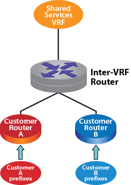
The Static Inter-VRF Route feature adds support for static inter-VRF routes. This enables the configuration of routes to destinations in one ingress VRF with an ability to specify a next-hop in a different egress VRF through a static configuration.
You can configure static inter-VRF routes in default and non-default VRFs. A different
egress VRF is achieved by “tagging” the next-hop or forwarding
via with a reference to an egress VRF (different from the source
VRF) in which that next-hop should be evaluated. Static inter-VRF routes
with ECMP next-hop sets in the same egress VRF or heterogenous egress VRFs
can be specified.
The Static Inter-VRF Route feature is independent and complementary to other mechanisms that can be used to setup local inter-VRF routes. The other supported mechanisms in EOS and the broader use-cases they support are documented here:
The configuration to setup static-Inter VRF routes in an ingress (source) VRF to forward IP traffic to a different egress (target) VRF can be done in the following modes:
This command creates a static route in one ingress VRF that points to a next-hop
in a different egress VRF.
Use the show ip route
vrf to display the egress VRF name if it differs from the
source VRF.
Example
switch# show ip route vrf vrf1
VRF: vrf1
Codes: C - connected, S - static, K - kernel,
O - OSPF, IA - OSPF inter area, E1 - OSPF external type 1,
E2 - OSPF external type 2, N1 - OSPF NSSA external type 1,
N2 - OSPF NSSA external type2, B - BGP, B I - iBGP, B E - eBGP,
R - RIP, I L1 - IS-IS level 1, I L2 - IS-IS level 2,
O3 - OSPFv3, A B - BGP Aggregate, A O - OSPF Summary,
NG - Nexthop Group Static Route, V - VXLAN Control Service,
DH - DHCP client installed default route, M - Martian,
DP - Dynamic Policy Route, L - VRF Leaked
Gateway of last resort is not set
S 1.0.1.0/24 [1/0] via 1.0.0.2, Vlan2180 (egress VRF default)
S 1.0.7.0/24 [1/0] via 1.0.6.2, Vlan2507 (egress VRF vrf3)
Limitations
For bidirectional traffic to work correctly between a pair of VRFs, static inter-VRF
routes in both VRFs must be configured.
Static Inter-VRF routing is supported only in multi-agent routing protocol mode.
Tunneling protocols encapsulate packets of a different protocol as the payload of a
larger frame for delivery within networks utilizing the encapsulating protocol.
Tunneling facilitates the delivery of payload over an incompatible delivery network and
creates a secure path through an untrusted network. Protocols that this chapter
describes include MPLS, Decap Groups, and Nexthop Groups.
The bfd vtep evpn command to configure the BGP PIC Edge for
EVPN VXLAN routes for remote VTEPs. This command is configured under the VXLAN
Tunnel Interface (VTI).
The no bfd vtep evpn command removes bfd vtep evpn
configuration from the running-config.
no bfd vtep evpnintervalinterval-millisecondsmin-rxmin-rx-millisecondsmultipliermultiplier-range
Parameters
interval Set transmit rate in milliseconds.
interval-milliseconds Rate in
milliseconds. Value ranges from 50 to
60000 milliseconds.
min-rx Set expected minimum incoming rate in
milliseconds.
min-rx-milliseconds Rate in milliseconds.
Value ranges from 50 to
60000 milliseconds.
multiplier Sets the BFD multiplier.
multiplier-range The value ranges from
3 to
50.
Example
In this example (assuming symmetric configuration on other PE devices) any BFD for
VXLAN session initiated on the VTI would have a detect time of
300ms (interval of 100ms multiplied by 3).
The encapsulation VXLAN layer-3 set next-hop igp-cost
command configures the underlay IGP metric for the VTEP reachability to be
considered for BGP best path selection in the IP VRF that is importing the EVPN
route.
The no encapsulation VXLAN layer-3 set next-hop igp-cost or
default encapsulation VXLAN layer-3 set next-hop
igp-cost command removes all the IGP cost for VTEP running
configurations on the switch.
Command Mode
BGP Address-Family Configuration
Command Syntax
encapsulation VXLAN layer-3 set next-hop igp-cost
no encapsulation VXLAN layer-3 set next-hop igp-cost
default encapsulation VXLAN layer-3 set next-hop igp-cost
Example
The following command configures the IGP cost for VTEP feature on the switch
:
The vlan e-tree places the switch in VLAN configuration mode
and allows configuration of E-Tree. By default, all VLANs have the E-Tree root role.Use
the no e-tree role leaf to set the VLAN to the default role,
root.
Command Mode
VLAN Configuration Mode
Command Syntax
[vlanvlan_id] e-treeroleleaf
Parameters
vlanvlan_id - Specify the VLAN to configure E-Tree.
role - Specify the role of the VLAN.
leaf - Specify the role as leaf.
Examples
Use the following command to set VLAN 100 as an E-Tree
leaf
role:
switch(config)# vlan 100
switch(config-vlan-100)# e-tree role leaf
To return the VLAN to the E-tree role root, use the
following
command:
switch(config)# vlan 100
switch(config-vlan-100)# no e-tree role leaf
ip hardware fib vxlan
leak routes
The leak routes command configures an inter-VRF
route-leaking policy to allow routes to be leaked from one VRF to another using a
route map.
The no leak routes and default leak
routes commands remove the specified route-leaking policy from
running-config.
The next-hop resolution disabled command disables the next-hop resolution in routes received from BGP-EVPN peers.
The no next-hop resolution disabled and the
default next-hop resolution disabled commands
enable the next-hop resolution in routes received from BGP-EVPN peers.
Command Mode
Router-BGP Address-Family Configuration
Command Syntax
next-hop resolution disabled
Example
This command disables the next-hop resolution
in routes received from BGP-EVPN peers.
The redistribute bgp evpn VXLAN command enables BGP-EVPN
routes to be redistributed to VCS, which in turn advertises them to all VTEPs within
the DC.
The no redistribute bgp evpn VXLAN and the
default redistribute bgp evpn VXLAN commands
disable the redistribution of BGP-EVPN routes to VCS.
Command Mode
CVX-VXLAN Configuration
Command Syntax
redistribute bgp evpn VXLAN
Example
This command enables redistribution of
BGP-EVPN routes to VCS.
switch(config)# cvx
switch(config-cvx)# no shutdown
switch(config-cvx)# service VXLAN
switch(config-cvx-VXLAN)# no shutdown
switch(config-cvx-VXLAN)# redistribute bgp evpn VXLAN
redistribute router-mac next-hop vtep primary
Use the redistribute router-mac next-hop vtep primary command
in the MAC VRF configuration mode to advertise an EVPN type-2 route for the VARP MAC
with a nexthop of the primary VTEP IP.
The redistribute service VXLAN command enables BGP to
redistribute the Layer 2 bridging information received from VCS.
The no redistribute service VXLAN and the
default redistribute service VXLAN commands
disable the redistribution of the bridging information received from VCS.
Command Mode
Router-BGP VNI Configuration
Command Syntax
redistribute service VXLAN
Example
This command enables redistribution of
the Layer 2 bridging information received from VCS.
The remote leaf host drop command allows the configuration of per-VLAN explicit drop routes for E-Tree.
Command Mode
VLAN E-Tree Configuration Mode
Command Syntax
remote leaf host drop
Example
Use the following commands to configure per-VLAN explicit drop routes for VLAN
100:
switch(config)#vlan 100
switch(config-vlan-100)#e-tree role leaf
switch(config-vlan-etree-100)#remote leaf host drop
route-target
The route-target command configures a well-known extended
community that is used by BGP-EVPN to export routes from or import routes into
MAC-VRF.
The no route-target and default
route-target commands delete the route-target
configuration.
Command Mode
Router-BGP VNI Configuration
Syntax
route-target [export |
import | both] rt
no route-target
default route-target
Parameters
export configures a well-known extended
community that is attached to the routes exported by BGP-EVPN.
import configures a well-knownextended
community that identifies the received routes that need to be imported into
the MAC-VRF specified by the VNI bundle.
both configures the same extended community
for import and export of routes.
rt route-target extended community.
Example
This command configures a well-known extended
community for import and export of routes.
range_target - Specify a route-target extended
community or a range of targets.
any-as:value - Specify a Local Administrator (LA) value
from 0 to 4294967295. Any two octet AS route target matching the LA value
imports the route target.
Examples
These commands import routes from the VPN table to
vrf-blue.
switch(config)# service routing protocols model multi-agent
switch(config)# mpls ip
switch(config)# router bgp 65001
switch(config-router-bgp)# vrf vrf-blue
switch(config-router-bgp-vrf-vrf-blue)# rd 2:2
switch(config-router-bgp-vrf-vrf-blue)# route-target import vpn-ipv4 10:10
switch(config-router-bgp-vrf-vrf-blue)# route-target import vpn-ipv6 10:20
These commands import routes from the EVPN table to
vrf-blue.
no parameters - Displays all routes of the
switch.
community - Displays routes filtered by the
specified community. Options include:
GSHUT - Displays the well known GSHUT
community.
aa:nn - Displays the AS and network
number, separated by a colon. The value ranges from
1 to
4294967295.
internet - Advertises route to the
Internet community.
local-as - Advertises route only to local
peers.
no-advertise -Does not advertise the
route to any peer.
no-export - Advertises route only within
the BGP-EVPN AS boundary.
comm_num - Displays the community number.
Values range from 1 to
4294967040.
detail - Displays detailed information of
routes.
esi esid - Displays routes filtered by the
specified Ethernet Segment Identifier (ESI).
extcommunity - Displays routes that match with BGP
or VPN extended community list. Options include:
esi-label esid - Displays routes filtered
by the specified value of ESI label. The value ranges from
0 to
16777215.
mac-mobility - Displays routes filtered by
the specified MAC mobility.
rt - Displays routes filtered by the
specified route target.
tunnel-encap VXLAN - Displays routes
filtered by the VXLAN tunnel encapsulation.
router-macH.H.H - Displays routes filtered by the
specified router MAC address.
host-flap - Displays routes that contains MAC
addresses blacklisted due to duplication.
instance - Displays routes with EVPN
instances.
large-communityAS:nn:nn - Displays routes filtered by the
specified large community.
next-hop - Displays routes filtered by next-hop
IPv4 or IPv6 addresses of remote VTEP.
rdadmin:local-assignment - Displays routes filtered
by the specified Route Distinguisher (RD).
route-type - Displays routes filtered by NLRI
route type.
summary - Displays a summary of routes.
vnivni_num - Displays routes filtered by the
specified VXLAN Network Identifier (VNI). Value ranges from
1 to
4294967294.
Examples
This command displays BGP-EVPN routes filtered by the VNI
3011.
switch(config-router-bgp-af)# show bgp evpn vni 3011
BGP routing table information for VRF default
Router identifier 2.0.2.2, local AS number 65002
Route status codes: s - suppressed, * - valid, > - active, # - not installed, E - ECMP head, e - ECMP
S - Stale, c - Contributing to ECMP, b - backup
% - Pending BGP convergence
Origin codes: i - IGP, e - EGP, ? - incomplete
AS Path Attributes: Or-ID - Originator ID, C-LST - Cluster List, LL Nexthop - Link Local Nexthop
Network Next Hop Metric LocPref Weight Path
* >Ec RD: 3.3.3.1:3011 auto-discovery 0 009a:f13b:53bb:8800:0000
1.1.1.1 - 100 0 65999 65001 i
* ec RD: 3.3.3.1:3011 auto-discovery 0 009a:f13b:53bb:8800:0000
1.1.1.1 - 100 0 65999 65001 i
* > RD: 3.3.3.2:3011 auto-discovery 0 009a:f13b:53bb:8800:0000
- - - 0 i
* >Ec RD: 3.3.3.1:3011 imet 1.1.1.1
1.1.1.1 - 100 0 65999 65001 i
* ec RD: 3.3.3.1:3011 imet 1.1.1.1
1.1.1.1 - 100 0 65999 65001 i
* > RD: 3.3.3.2:3011 imet 1.1.1.2
- - - 0 i
cvx(config-router-bgp-af)#
This command displays the prefixes exported to the respective VPN table,
along with the route
distinguisher.
switch(config)# show bgp evpn
BGP routing table information for VRF default
Router identifier 1.1.1.1, local AS number 65001
Route status codes: s - suppressed, * - valid, > - active, # - not installed, E - ECMP head, e - ECMP
S - Stale, c - Contributing to ECMP, b - backup
% - Pending BGP convergence
Origin codes: i - IGP, e - EGP, ? - incomplete
AS Path Attributes: Or-ID - Originator ID, C-LST - Cluster List, LL Nexthop - Link Local Nexthop
Network Next Hop Metric LocPref Weight Path
* > RD: 400:1 ip-prefix 45.0.0.1/32
- - - 0 i
* > RD: 400:1 ip-prefix 52.0.0.1/32
- - - 0 i
* > RD: 400:1 ip-prefix 120.0.0.0/24
- - - 0 i
* > RD: 400:1 ip-prefix 130.0.0.0/24
- - - 0 i
* > RD: 400:1 ip-prefix 130.0.1.0/24
show bgp evpn sanity
The show bgp evpn command displays information about the
BGP-EVPN configuration attributes such as any inconsistencies as well as potential errors in the EVPN operational state.
The command performs the following sanity checks for EVPN:
Domain encapsulation consistency
Default-gateway redistribution override detection
MAC-VRF route-distinguisher check to warn for duplicate local RDs
D-PATH domain ID verification
Domain ID uniqueness
Type 5 route configuration validation
Remote RD/RT checks
MAC-VRF neighbor verification
I-ES encapsulation consistency check for DCI environments
Command Mode
Global Configuration
Command Syntax
show bgp evpn sanity [brief | detail]
Parameters
The output displays the following categories when detecting inconsistencies or warnings:
General EVPN
Layer 2 EVPN
Layer 3 EVPN
EVPN VXLAN
EVPN MPLS
EVPN DCI
Examples
The command displays the following output when detecting an inconsistency in the General EVPN configuration and a warning for the Layer 2
EVPN configuration:
switch# show bgp evpn sanity
Category Status
--------- -------
General FAIL
L2 WARN
Thecommand displays the following output when detecting a missing configuration on the
EVPN peer 10.0.0.2 and the MAC-VRF 100 does not import or export a route target. All
other verifications pass the sanity checks.
switch# show bgp evpn sanity brief
Category Check Status Detail
-------- -------------------- ------ -------------------------------------------------
General Send community FAIL Extended community not sent to 10.0.0.2
L2 MAC-VRF route-target WARN The MAC-VRF VLAN 100 does not import or export a route-target
import and export
The show bgp evpn sanity detail command displays all individual verifications regardless of the status:
switch show bgp evpn sanity detail
General Send community FAIL Extended community not sent to 10.0.0.2
General Multi-agent mode OK
General Neighbor established OK
General Domain encapsulation OK
consistency
L2 MAC-VRF route-target WARN The MAC-VRF VLAN 100 does not import or export a
import and export route-target
L2 MAC-VRF OK
route-distinguisher
L2 MAC-VRF local OK
neighbor configured
L2 MAC-VRF redistribute OK
L2 MAC-VRF SVI IP OK
redistribution
consistency
L2 MAC-VRF overlapping OK
VLAN
L2 Suppressed MAC OK
VXLAN VLAN to VNI map for OK
MAC-VRF
VXLAN VRF to VNI map for OK
IP-VRF
DCI MAC-VRF remote route OK
distinguisher
DCI MAC-VRF remote route OK
target import and
export
DCI MAC-VRF remote OK
neighbor configured
DCI Domain-ID uniqueness OK
DCI D-PATH EVPN OK
Domain-ID
DCI Type 5 routes with OK
next-hop-self and
path aggregation
DCI Type 5 routes with OK
next-hop-self and
multi-domain VRF
DCI I-ES Encapsulation OK
Consistency
show e-tree vlan
The show e-tree vlan command displays configuration information about E-Tree on VLANs.
Command Mode
EXEC
Command Syntax
show e-tree vlan
Example
To display information about E-Tree on VLANs, use the following
command:
switch# show e-tree vlan
VLAN E-Tree Role Remote Leaf Install Mode
---------- -------------- ------------------------
100 Leaf Install drop route
200 Leaf Do not install
show ip bgp vrf
The show ip bgp vrf command displays the type of VPN from
the imported route. It indicates that the IPv4 route has been leaked and displays
source VRF information.
Command Mode
Global Configuration
Command Syntax
show ip bgp vrf [vrf_name |
all | default]
Parameters
vrf_name name of the VRF.
all displays summary of all VRFs.
default default virtual routing and forwarding
instance.
Example
This command displays the leaked and source VRF
information.
switch(config)# show ip bgp 13.0.0.0/24 vrf vrf-blue
BGP routing table information for VRF vrf-blue
Router identifier 5.0.0.2, local AS number 65001
BGP routing table entry for 130.110.61.0/24
4.0.0.3 from 4.0.0.3 (52.0.0.1), imported EVPN route, RD 400:1
Origin IGP, metric -, localpref 100, weight 0, valid, external,best
Extended Community: Route-Target-AS:4000:1 TunnelEncap:tunnelTypeVXLAN
EvpnRouterMac:74:83:ef:0b:70:f3
Leaked from VRF vrf-red
show ip route vrf
The show ip route vrf command displays leaked prefixes with
the labelL in the output that indicates that
the IPv4 route has been leaked. It also displays information about the source VRF
from which these prefixes have been leaked.
Command Mode
Global Configuration
Command Syntax
show ip route vrf [vrf_name |
all]
Parameters
vrf_name name of the VRF.
all displays summary of all VRFs.
Example
These commands display the OSPF or OSPFV3 leaked routes as redistribute
ospf and redistribute ospfv3 are
configured on the source VRF
vrf-red.
switch(config)# show ip route vrf vrf-blue
VRF: vrf-blue
Codes: C - connected, S - static, K - kernel,
O - OSPF, IA - OSPF inter area, E1 - OSPF external type 1,
E2 - OSPF external type 2, N1 - OSPF NSSA external type 1,
N2 - OSPF NSSA external type2, B I - iBGP, B E - eBGP,
R - RIP, I L1 - IS-IS level 1, I L2 - IS-IS level 2,
O3 - OSPFv3, A B - BGP Aggregate, A O - OSPF Summary,
NG - Nexthop Group Static Route, V - VXLAN Control Service,
DH - DHCP client installed default route, M - Martian,
DP - Dynamic Policy Route, L - VRF Leaked
Gateway of last resort is not set
C 5.0.0.2/31 is directly connected, Ethernet14
B L 57.0.0.3/32 [200/0] (source VRF vrf-red) via 4.0.0.3, Ethernet11
B L 45.0.0.1/32 [200/0] (source VRF vrf-red) via 4.0.0.3, Ethernet11
B L 52.0.0.1/32 [200/0] (source VRF vrf-red) via 4.0.0.3, Ethernet11
B L 120.0.0.0/24 [200/0] (source VRF vrf-red) via 4.0.0.3, Ethernet11
B L 130.0.0.0/24 [200/0] (source VRF vrf-red) via 4.0.0.3, Ethernet11
B L 130.0.1.0/24 [200/0] (source VRF vrf-red) via 4.0.0.3, Ethernet11
B L 130.0.2.0/24 [200/0] (source VRF vrf-red) via 4.0.0.3, Ethernet11
B L 130.0.3.0/24 [200/0] (source VRF vrf-red) via 4.0.0.3, Ethernet11
show ipv6 bgp vrf
The show ipv6 bgp vrf command displays the type of VPN from
the imported route. It shows an indication that the IPv6 route has been leaked and
source VRF information is displayed.
Command Mode
Global Configuration
Command Syntax
show ipv6 bgp vrf [vrf_name |
all | default]
Parameters
vrf_name name of the VRF.
all displays a summary of all VRFs.
default default virtual routing and forwarding
instance.
Example
This command displays the leaked and source VRF
information.
switch(config)# show ipv6 bgp 2001:10:1:0::102/64 vrf default
BGP routing table information for VRF default
Router identifier 218.218.218.218, local AS number 34
Route status codes: s - suppressed, * - valid, > - active, # - not installed, E
- ECMP head, e - ECMP
S - Stale, c - Contributing to ECMP, b - backup, L -
labeled-unicast
% - Pending BGP convergence
Origin codes: i - IGP, e - EGP, ? - incomplete
AS Path Attributes: Or-ID - Originator ID, C-LST - Cluster List, LL Nexthop -
Link Local Nexthop
Network Next Hop Metric LocPref Weight Path
* > 2000:0:14:120::/64 2001:db8:1111:9000:: - 100 109 i
* 2000:0:14:120::/64 2001:db8:156:1010::2 - 100 0 i
* 2000:0:14:120::/64 2001:db8:152:1010::2 - 100 0 i
* 2000:0:14:120::/64 2001:db8:203:1010::2 - 100 0 i
show ipv6 route vrf
The show ipv6 route vrf command displays leaked prefixes
with the labelL in the output that indicates
that the IPv6 route has been leaked. It also displays information about the source
VRF from which these prefixes have been leaked.
Command Mode
Global Configuration
Command Syntax
show ipv6 route vrf [vrf_name |
all]
Parameters
vrf_name the name of the VRF.
all displays a summary of all VRFs.
Example
These commands display the OSPF or OSPFV3 leaked routes as redistribute
ospf and redistribute ospfv3 are
configured on the source VRF
vrf-red.
switch(config)# show ipv6 route vrf vrf-blue
VRF: vrf-blue
Displaying 802 of 802 IPv6 routing table entries
Codes: C - connected, S - static, K - kernel, O3 - OSPFv3, B - BGP, R - RIP, A B - BGP Aggregate,
I L1 - IS-IS level 1, I L2 - IS-IS level 2, DH - DHCP, NG - Nexthop Group Static Route, M - Martian,
DP - Dynamic Policy Route, L - VRF Leaked
B L 18::1/128 [200/0] (source VRF vrf-red)
via 4::3, Ethernet11
B L 6::2/127 [200/0] (source VRF vrf-red)
via fe80::7683:efff:fe0b:963d, Ethernet11
B L 45::1/128 [200/0] (source VRF vrf-red)
via fe80::7683:efff:fe0b:963d, Ethernet11
B L 130::/64 [200/0] (source VRF vrf-red)
via fe80::7683:efff:fe0b:963d, Ethernet11
B L 130:0:0:1::/64 [200/0] (source VRF vrf-red)
via fe80::7683:efff:fe0b:963d, Ethernet11
B L 130:0:0:2::/64 [200/0] (source VRF vrf-red)
via fe80::7683:efff:fe0b:963d, Ethernet11
B L 130:0:0:3::/64 [200/0] (source VRF vrf-red)
show l2rib input all
Use the show l2rib input all command to display the Layer 2 RIB
input tables migration process.
advertised displays the advertised route
entries in the MAC forwarding table.
received displays the received route entries
in the MAC forwarding table.
addressH.H.H displays route entries that are filtered
by the specified MAC addresses.
evpn displays route entries filtered by
BGP-EVPN.
hsc displays route entries filtered by
Hardware Switch Controller (HSC).
mss displays route entries filtered by Macro
Segmentation Service (MSS).
switch displays route entries that are
filtered by the specified switch or all switches. Options include:
Word Hostname, IP address or ID of the
switch.
all all switches.
vnivnid displays route entries filtered by the
specified VXLAN Network Identifier (VNI). Value ranges from
1 to
4294967294.
vtepA.B.C.D displays route entries filtered by the
specified IP address of the remote Virtual Tunnel End Point (VTEP).
Examples
This command displays the route entries in MAC forwarding table advertised
to BGP-EVPN
peers.
cvx# show service VXLAN address-table advertised evpn
Advertised Mac Address Table
----------------------------------------------------------
VNI Mac Address VTEP Moves
----------- ----------------- --------------- -----
1000 02:01:62:01:00:00 10.0.0.1 1
Total Mac Addresses for this criterion: 1
Advertised Flood Table
---------------------------------------------------
VNI Mac Address VTEP(s)
---------- ----------------- ------------------------------
1000 00:00:00:00:00:00 10.0.0.1 10.0.0.2
Total Mac Addresses for this criterion: 1
cvx#
This command displays the route entries in MAC forwarding table received
from BGP-EVPN
peers.
switch# show service VXLAN address-table received evpn
Received Mac Address Table
-------------------------------------------------------------
Source VNI Mac Address VTEP Moves
----------- -------- ----------------- ----------- -----
EVPN 1000 02:01:62:02:00:00 10.0.0.3 1
Total Mac Addresses for this criterion: 1
Received Flood Table
--------------------------------------------------------------
Source VNI Mac Address VTEP
----------------- ----------- ----------------- --------------
EVPN 1000 00:00:00:00:00:00 10.0.0.3
EVPN 1000 00:00:00:00:00:00 10.0.0.4
Total Mac Addresses for this criterion: 2
switch#
show vrf leak flapping
The show vrf leak flapping command displays the flapping
prefixes of the routes leaked from one VRF to another VRF. Routes that are detected
as “flapping” are blocked considering the future leaking policy execution.
Command Mode
EXEC
Command Syntax
show vrf leak flapping
Parameters
destination displays flapping prefixes
destined to a VRF.
prefix displays flapping routes for a
prefix.
source displays flapping prefixes sourced from
a VRF.
vrf displays flapping prefixes associated with
a VRF.
Example
This command displays the flapping prefixes of the leaked
routes.
switch# show vrf leak flapping
Age Source VRF Destination VRF Prefix Created At
-------- ---------------- --------------------- ----------------- -------------
141 VRF1 VRF2 10.0.2.0/24 3357281.40992
show VXLAN control-plane
To enable the user to quickly view which control planes and sources are importing
reachability information into which VLANs, use the following show command:
export Restricts output to VLANs exporting to a
control plane.
vlan Specifies specific VLANs to display
control plane information.
$ List end.
vlan_id VLAN ID. Range
1-4094.
import Restricts output to VLANs importing from a
control plane.
$ List end.
vlan_id VLAN ID. Range
1-4094.
vlan Specifies specific VLANs to display control plane
information.
$ List end.
vlan_id VLAN ID. Range
1-4094.
vlan (VLAN-AWARE-Bundle configuration mode)
The vlan add/ remove command configures the VLAN range
string in a VLAN-AWARE-BUNDLE. When the add and remove options are not used, the
currently configured range is replaced by the new one. The add and remove options
update the currently configured range-aware bundles by adding or removing the
provided VLAN range from the currently configured range respectively.
Command Mode
VLAN-AWARE-BUNDLE Configuration
Command Syntax
vlan [add | remove]
range
Parameter
range is the range specified.
Example
These commands take an existing vlan-aware-bundle configuration,
corporate_100, and modify it with the add and
remove options.
(Existing configuration for corporate_100)
vlan-aware-bundle corporate_100
rd 1.1.1.1:100
route-target both 100:100
vlan 1-10
switch(config-vlan-aware-bundle)#vlan add 1000
(Modified configuration for corporate_100)
vlan-aware-bundle corporate_100
rd 1.1.1.1:100
route-target both 100:100
vlan 1-10, 1000
switch(config-vlan-aware-bundle)#vlan remove 5
(Updated configuration for corporate_100)
vlan-aware-bundle corporate_100
rd 1.1.1.1:100
route-target both 100:100
vlan 1-4, 6-10, 1000
vni-aware-bundle
The vni-aware-bundle command configures a BGP MAC-VRF
containing Layer 2 routes from a group of VXLAN Network Identifiers (VNI).
Command Mode
Router BGP Configuration
Command Syntax
vni-aware-bundlevni_bundle_name
Parameter
vni_bundle_name VNI bundle name.
Example
This command configures MAC-VRF BGP to support
VNI bundle1.
In EVPN deployment with VXLAN underlay when an EVPN type-5 prefix is imported into an IP VRF,
the IGP cost of the underlay VTEP reachability is not considered as part of BGP best-path
selection post import. Therefore, if such a prefix is reachable via more than one VTEPs, the
IGP metric step in the BGP best-path selection algorithm does not filter out any paths
regardless of the underlay’s IGP metric for the VTEP reachability. If ECMP is enabled in the
overlay and multiple paths are found to be otherwise equivalent, such paths would form ECMP
regardless of the IGP metric. This is the default behavior.
However, the behavior can be overridden by the following configuration command
encapsulation VXLAN layer-3 set next-hop igp-cost in the BGP
Route Address Family mode for address-family evpn as
shown.
The encapsulation VXLAN layer-3 set next-hop igp-cost command
causes the underlay IGP metric for the VTEP reachability to be considered for BGP best path
selection in the IP VRF that is importing the EVPN route. An IGP protocol such as OSPF, ISIS,
or static configuration could be the source of such a metric value.
Note: This feature is available only with the multi-agent routing protocol model.
Configuring EVPN IGP Cost for VTEP Reachability
Consider a topology of four routers leaf1,
leaf2, leaf3 and
rtr1 as shown in the figure.
Figure 1. EVPN IGP Cost for VTEP
There could be IGP running among the four routers, but for simplicity let's have
static routes with IGP metric on leaf1 to
lo0 of border leaf2 and
leaf3 (and vice-versa for reverse reachability on the respective
routers, though that configuration not shown
here):
leaf1#
ip route 11.0.1.1/32 10.0.0.2 metric 340
ip route 11.0.2.1/32 10.0.0.2 metric 350
Following are the IP routes in the
default VRF on leaf1.
leaf1# show ip route
VRF: default
Codes: C - connected, S - static, K - kernel,
O - OSPF, IA - OSPF inter area, E1 - OSPF external type 1,
E2 - OSPF external type 2, N1 - OSPF NSSA external type 1,
N2 - OSPF NSSA external type2, B - BGP, B I - iBGP, B E - eBGP,
R - RIP, I L1 - IS-IS level 1, I L2 - IS-IS level 2,
O3 - OSPFv3, A B - BGP Aggregate, A O - OSPF Summary,
NG - Nexthop Group Static Route, V - VXLAN Control Service,
DH - DHCP client installed default route, M - Martian,
DP - Dynamic Policy Route, L - VRF Leaked,
RC - Route Cache Route
Gateway of last resort:
S 0.0.0.0/0 [1/0] via 10.0.0.2, Ethernet2
C 10.0.0.0/24 is directly connected, Ethernet2
C 11.0.0.1/32 is directly connected, Loopback0
S 11.0.1.1/32 [1/340] via 10.0.0.2, Ethernet2
S 11.0.2.1/32 [1/350] via 10.0.0.2, Ethernet2
Following
are eBGP-multihop EVPN neighbor pairs with VXLAN as
underlay:
leaf1 (ASN-300) ⇔
leaf2 (ASN-301)
leaf1 (ASN-300) ⇔
leaf3 (ASN-302)
Consider an example where a prefix
20.0.100.1/32 is reachable behind two VTEPs
leaf2 and leaf3 as learnt on leaf1 via
eBGP EVPN Type-5 routes.
Following EVPN paths will show for
20.0.100.1/32 on
leaf1:
leaf1(config)# show bgp evpn detail
BGP routing table entry for ip-prefix 20.0.100.1/32, Route Distinguisher: 11.0.1.1:0
Paths: 1 available
301
11.0.1.1 from 10.0.1.1 (0.0.2.1)
Origin INCOMPLETE, metric -, localpref 100, weight 0, valid, external, best
Extended Community: Route-Target-AS:64500:20000 TunnelEncap:tunnelTypeVXLAN
EvpnRouterMac:00:00:78:03:00:00
VNI: 20000
BGP routing table entry for ip-prefix 20.0.100.1/32, Route Distinguisher: 11.0.2.1:0
Paths: 1 available
302
11.0.2.1 from 10.0.2.1 (0.0.3.1)
Origin INCOMPLETE, metric -, localpref 100, weight 0, valid, external, best
Extended Community: Route-Target-AS:64500:20000 TunnelEncap:tunnelTypeVXLAN
EvpnRouterMac:00:00:78:04:00:00
VNI: 20000
Show Commands
By default, since the underlay IGP cost for the VTEP reachability is not used for best path
selection in the imported EVPN Type-5 routes, either of the two paths could be selected as the
best path. If ECMP is configured in the importing VRF, then the two paths will form ECMP. The
following example shows an ECMP that is allowed in the importing VRF vrf1.
switch1# show ip route vrf vrf1
VRF: vrf1
Codes: C - connected, S - static, K - kernel,
O - OSPF, IA - OSPF inter area, E1 - OSPF external type 1,
E2 - OSPF external type 2, N1 - OSPF NSSA external type 1,
N2 - OSPF NSSA external type2, B - BGP, B I - iBGP, B E - eBGP,
R - RIP, I L1 - IS-IS level 1, I L2 - IS-IS level 2,
O3 - OSPFv3, A B - BGP Aggregate, A O - OSPF Summary,
NG - Nexthop Group Static Route, V - VXLAN Control Service,
DH - DHCP client installed default route, M - Martian,
DP - Dynamic Policy Route, L - VRF Leaked,
RC - Route Cache Route
B E 20.0.100.1/32 [200/0] via VTEP 11.0.1.1 VNI 20000 router-mac 00:00:78:02:00:00
via VTEP 11.0.2.1 VNI 20000 router-mac 00:00:78:03:00:00
switch1# show ip bgp 20.0.100.1/32 vrf vrf1
BGP routing table information for VRF vrf1
Router identifier 11.0.0.1, local AS number 300
BGP routing table entry for 20.0.100.1/32
Paths: 2 available
302
11.0.2.1 from 10.0.2.1 (0.0.3.1), imported EVPN route, RD 11.0.2.1:0
Origin INCOMPLETE, metric 0, localpref 100, IGP metric 350, weight 0, tag 0
Received 01:11:00 ago, valid, external, ECMP head, ECMP, best, ECMP contributor
Extended Community: Route-Target-AS:64500:20000 TunnelEncap:tunnelTypeVXLAN
EvpnRouterMac:00:00:78:04:00:00
Remote VNI: 20000
Rx SAFI: Unicast
301
11.0.1.1 from 10.0.1.1 (0.0.2.1), imported EVPN route, RD 11.0.1.1:0
Origin INCOMPLETE, metric 0, localpref 100, IGP metric 340, weight 0, tag 0
Received 01:11:00 ago, valid, external, ECMP, ECMP contributor
Not best: ECMP-Fast configured
Extended Community: Route-Target-AS:64500:20000 TunnelEncap:tunnelTypeVXLAN
EvpnRouterMac:00:00:78:03:00:00
Remote VNI: 20000
Rx SAFI: Unicast
The configuration command encapsulation VXLAN layer-3 set next-hop
igp-cost under address-family evpn will cause the
underlay IGP cost to be taken into account and only VTEP 11.0.1.1
with lower IGP cost will be selected as shown
below:
switch1# show ip route vrf vrf1
VRF: vrf1
Codes: C - connected, S - static, K - kernel,
O - OSPF, IA - OSPF inter area, E1 - OSPF external type 1,
E2 - OSPF external type 2, N1 - OSPF NSSA external type 1,
N2 - OSPF NSSA external type2, B - BGP, B I - iBGP, B E - eBGP,
R - RIP, I L1 - IS-IS level 1, I L2 - IS-IS level 2,
O3 - OSPFv3, A B - BGP Aggregate, A O - OSPF Summary,
NG - Nexthop Group Static Route, V - VXLAN Control Service,
DH - DHCP client installed default route, M - Martian,
DP - Dynamic Policy Route, L - VRF Leaked,
RC - Route Cache Route
B E 20.0.100.1/32 [200/0] via VTEP 11.0.1.1 VNI 20000 router-mac 00:00:78:02:00:00
switch1(config)# show ip bgp 20.0.100.1/32 vrf vrf1
BGP routing table information for VRF vrf1
Router identifier 11.0.0.1, local AS number 300
BGP routing table entry for 20.0.100.1/32
Paths: 2 available
301
11.0.1.1 from 10.0.1.1 (0.0.2.1), imported EVPN route, RD 11.0.1.1:0
Origin INCOMPLETE, metric 0, localpref 100, IGP metric 340, weight 0, tag 0
Received 00:23:35 ago, valid, external, best
Extended Community: Route-Target-AS:64500:20000 TunnelEncap:tunnelTypeVXLAN
EvpnRouterMac:00:00:78:03:00:00
Remote VNI: 20000
Rx SAFI: Unicast
302
11.0.2.1 from 10.0.2.1 (0.0.3.1), imported EVPN route, RD 11.0.2.1:0
Origin INCOMPLETE, metric 0, localpref 100, IGP metric 350, weight 0, tag 0
Received 00:23:35 ago, valid, external
Not best: IGP cost
Extended Community: Route-Target-AS:64500:20000 TunnelEncap:tunnelTypeVXLAN
EvpnRouterMac:00:00:78:04:00:00
Remote VNI: 20000
Rx SAFI: Unicast
EVPN Multicast virtual routing and forwarding (VRF) Leaking forwards multicast
traffic from a sender in a tenant or external domain (VRF) to a different domain
(VRF) with connected receivers. The source VRF refers to the VRF of the
multicast sender, and the receiver VRF refers to the VRF of the multicast
receiver.
Typically, a multicast receiver sends IGMP messages to a multicast stream, and a last
hop router converts the IGMP message to a Protocol Independent Multicast (PIM)
message and propagates them upstream on the network. When a VRF receives an IGMP or
PIM message, a corresponding VRF leak occurs where the IGMP or PIM messages leak to
the source VRF, which the source VRF processes. The corresponding EVPN Selective
Multicast Ethernet Tag (SMET) route originates with the Supplementary Broadcast
Domain (SBD) route target of the VRF and the route distinguisher (RD) where the
sources connect. The receiver VRF RT and RD do not originate SMET routes.
When configuring EVPN Multicast VRF Leaking, the source VRF contains the Multicase
Outgoing Interface (OIF) list of multicast routes from the receiver VRF. When the
source VRF forwards traffic, the VRF sends a copy of the OIF list across the
VRF.
EVPN Multicast VRF Leaking supports a per multicast group configuration to leak
multicast traffic.
Note: Configure EVPN Multicast VRF Leaking with caution. Any network design or
configuration issues could potentially cause traffic to blackhole, send multiple
copies of traffic to the same receiver, or create traffic looping, which may impact
traffic on your network.
In the following EVPN topology, two VRF tenants, red and blue, have
multicase receivers and senders. The receiver, Rb1, on the blue VRF
looks for group G on VRF, red, which has the resources. To enable the
feature, configure VRF Leaking for group G on the PE connected to the
Rb1 with VRF red as the source VRF.
In the example topology, the control flow works as follows:
Rb1 sends an IGMP join request for (*,G), and the host device
is unaware of VRF Leaking.
VRF blue has the configuration for VRF Leaking for G, so the egress
Provider Edge (PE) router sends a SMET to the red VRF, and does not send a
SMET to the blue VRF or the VLAN100.
The ingress PE connected to the source on VRF red, sends
VXLAN-encapsulated multicast packets with the VNI of the source VLAN across
the EVPN core.
The egress PE receives the VXLAN packet, decapsulates it, and routes the
data packet to VRF blue.
Note: EVPN multi-homed receivers support VRF Leaking, and the configuration should be
identical on both designated-forwarder (DF) and non-DF VTEPs for the multi-homed
Ethernet segment.
EVPN Multicast VRF Leaking with a PIM EVPN Gateway (PEG)
On an EVPN network with a PEG role, the PEG acts as the rendezvous point (RP) for the
leaked groups. The PEG also functions as the Rendezvous Point (RP) of the source
VRF, which follows the PIM network model, where the PEG acts as the RP of the source
and receiver VRFs. The configuration requires synchronization using a protocol such
as Multicast Source Discovery Protocol (MSDP), and the source synchronization may be
necessary with the source and receiver VRFs.
If an RP exists in the external PIM domain, then Multicast VRF Leaking can be
configured on that RP instead of the PEG, but this requires that both the source and
receiver VRFs extend into the PIM domain that includes the RP.
In this case, the sources on the EVPN tenant VRFs exist in a different VRF from the
RP, and the unicast route leaks to the source from the tenant VRF into the external
domain VRF to build the multicast trees and perform Reverse Path Forwarding (RPF)
validation.
Figure 2. Figure 2 - Multicast Traffic Flow with VRF Leaking on the PEG
Using MLAG as a PEG on an EVPN Network
When configuring VRF Leaking on MLAG devices used as PEGS, configure the MLAG devices
as a PEG in both the receiver VRF and the source VRF. Typically, the external PIM
domain connects to the receiver. To enable PEG functionality on the source VRF,
configure a stub VLAN and a corresponding SVI on both MLAG peers. Enable PIM on the
SVIs of both peers and attach them to the source VRF. This enables PEG functionality
in the source VRF as well.
Sharing an Equivalence Class Entry Across Multiple VRFs
This enables the sharing of the same Forwarding Equivalence Class (FEC) entry across multiple
VRF’s and achieves higher scale in VPN deployments by making optimal use of
hardware resources. The VPN path routes are imported to multiple VRF for
MPLS VPN address family in BGP, individual FEC entry in the hardware table
is used for each VRF.
The following configuration in router BGP mode at BGP instance level allows
sharing FEC, when the VPN path is imported to multiple VRFs.
bgp fec skip in-place update
The following configures disable FEC and restores default configuration.
[no| default] bgp fec skip in-place update
Note: Changing the configuration in a production system may increase FEC
usage.
The following example displays BGP VPN-IPv4 routes for prefix
20.0.1.0/24, which is imported to
four VRFs.
switch# show bgp vpn-ipv4 20.0.1.0/24 detail
BGP routing table information for VRF default
Router identifier 0.0.0.1, local AS number 300
BGP routing table entry for IPv4 prefix 20.0.1.0/24, Route Distinguisher: 11.0.1.1:0
Paths: 1 available
301
11.0.1.1 from 10.0.0.2 (0.0.1.1)
Origin IGP, metric -, localpref 100, weight 0, valid, external, best
Extended Community: Route-Target-AS:300:0 Route-Target-AS:301:0
MPLS label: 116507
This route was using four FEC entries for each VRF before the change.
Arista switches support Audio Video Bridging (AVB) and the associated protocols. This section
describes AVB concepts and the implementation of associated protocols.
Audio Video Bridging (AVB)
is a protocol set that provides precision time synchronization, admission
control, queuing reservation, and guaranteed bandwidth of professional
grade quality audio and video across an IP network.
Supported AVB protocols include:
Generalized Precision Time Protocol (gPTP)
Multiple Stream Reservation Protocol (MSRP)
Multiple VLAN Registration Protocol (MVRP)
These AVB features are supported on Arista 7280, 7150 Series, and 7500E Series switches:
gPTP with hardware time stamping
gPTP Grandmaster function
MSRP protocol on Ethernet interfaces: stream admission control and
propagation
Control plane protection for PTP and MSRP control frames
MVRP
Traffic classes 2 and 3 for AVB traffic
Traffic shaping on egress ports
These AVB features are not available on Arista switches:
MSRP protocol on LAGs
MSRP co-ordination with gPTP; streams are allowed even when gPTP is not in
sync
Generalized Precision Time Protocol (gPTP) is a network time synchronization standard for bridged Local Area Networks based on the IEEE 1588v2 Precision Time Protocol and supports the AVB protocol standards.
Time synchronization in a gPTP domain is conducted the same way as in a PTP 1588 domain. A grandmaster is selected through the best grand master clock algorithm and distributes timing synchronization information to all directly attached peers. This information is propagated across the network to provide a common time reference to all Audio and Video end stations.
MVRP
Multiple VLAN Registration
Protocol (MVRP) is an application of Multiple Registration Protocol used
by AVB endpoints to dynamically register and unregister VLANs on an interface.
When an interface wishes to join a VLAN
advertised by an MSRP talker (to receive a stream), MVRP sends a Join
message. On receiving the Join message, the interface is added to the
VLAN. If the VLAN does not already exist, MVRP dynamically creates the
VLAN and propagates it through the network.
MVRP events post Syslog messages, with the severity level of INFO for each message.
MVRP_VLAN_JOIN
MVRP VLAN Join received/transmitted on an interface.
MVRP_VLAN_LV
MVRP VLAN Leave received/transmitted on an interface.
MVRP_ERROR
MVRP Join was discarded due to an error.
MSRP
Multiple Stream Registration Protocol (MSRP) is a signaling protocol that allows end
stations (nodes) to reserve network resources and ensure QoS for communicating with
other end stations.
MSRP nodes are specified as talkers or listeners:
Talker nodes transmit multimedia streams to other nodes in the AVB network.
Listener nodes receive multimedia streams from the AVB talker nodes.
MSRP is implemented by the switch on individual interfaces. MSRP is active when it is
enabled on at least one interface, and stopped when it is disabled on all interfaces.
MSRP uses Multiple Registration Protocol (MRP) to facilitate attribute registrations and
distribution across connected end points in a LAN environment.
MSRP events post Syslog messages, with the severity level of INFO for each message.
MSRP_SR_CLASS_TRANSITION
MSRP SR Class state transition occurred on an
interface.
MSRP_TALKER_ADV_JOIN
Talker Advertise Join message for a stream
was transmitted/received on an interface.
MSRP_TALKER_FAIL_JOIN
Talker Failed Join message for a stream
was transmitted/received on an interface.
MSRP_LISTENER_JOIN
Listener Join message for a stream was
transmitted/received on an interface.
MSRP_DOMAIN_JOIN
Domain Join message was transmitted/received
on an interface.
MSRP_TALKER_ADV_LV
Talker Advertise Leave message for a stream
was transmitted/received on an interface.
MSRP_TALKER_FAIL_LV
Talker Failed Leave message for a stream
was transmitted/received on an interface.
MSRP_LISTENER_LV
Listener Leave message for a stream was
transmitted/received on an interface.
MSRP_DOMAIN_LV
Domain Leave message was transmitted/received on
an interface.
MSRP_BW_ALLOC_SUCCESS
MSRP Bandwidth was allocated for a
listener on an interface.
MSRP_BW_ALLOC_FAIL
MSRP Bandwidth could not be allocated for a
listener on an interface.
MSRP_BW_DEALLOC
MSRP Bandwidth was de-allocated for a listener
on an interface.
MSRP_ERROR
MSRP Join was discarded because of an
error.
MRP
Multiple Registration Protocol (MRP) protocol includes MSRP and MVRP, and allows participants in an MRP application to register attributes with participants in a Bridged Local Area Network (BLAN).
MSRP configuration information and status is displayed with the show
msrp command.
Example
This command displays the MSRP status for interfaces ethernet
41-43.
switch(config)# show msrp interfaces ethernet 41-43
MSRP Global Status : Enabled
Max Frame Size : 1522
Max Fan-In Ports : No limit
Delta
Class Supported Priority Bandwidth
----- --------- -------- ---------
A Y 3 75%
B Y 2 0%
Legend
------
Adv : Talker Advertise Fail : Talker Fail
AskFail : Listener Asking Failed Rdy : Listener Ready
RdyFail : Listener Ready Failed
Admin Sr Talkers Listeners Bandwidth
Port State Pvid Class Oper State Adv Fail Rdy AskFail Allocated
---- -------- ----- ------ --------------- ---- ----- ---- -------- ---------
Et41 Active 5 A Boundary 1 0 1 0 200kbps
B Core 0 0 0 1 100kbps
Et42 Active 3 A Core 0 0 1 1 50kbps
B WaitingForPeer 1 0 0 0 20kbps
Et43 Disabled 3
switch(config)#
Stream data is available for the talker and listener. The show msrp interfaces command displays the status
and configuration information for each stream.
Examples
This command displays data for listener station streams on interfaces ethernet
1-2.
switch(config)# show msrp interfaces ethernet 1-2
MSRP Global Status : Enabled
Max Frame Size : 1522
Max Fan-In Ports : No limit
Delta
Class Supported Priority Bandwidth
----- --------- -------- ---------
A Y 3 75%
B Y 2 0%
Legend
------
Adv : Talker Advertise Fail : Talker Fail
AskFail : Listener Asking Failed Rdy : Listener Ready
RdyFail : Listener Ready Failed
Listeners
Port Stream Id Dec Dir
-------- -------------------- --------- ------
Et1 0000.0000.0000.002a AskFail Tx
0000.0000.0000.029a RdyFail Rx
0000.0000.0000.038f AskFail Rx
Et2 0000.0000.0000.002a AskFail Rx
0000.0000.0000.029a RdyFail Rx
0000.0000.0000.038f AskFail Tx
switch(config)#
This command displays data for talker station streams on interfaces ethernet
1-2.
switch(config)# show msrp interfaces ethernet 1-2 talkers
Legend
------
Adv : Talker Advertise Fail : Talker Fail
Talkers
Port Stream Id Dec Dir FailCode
-------- -------------------- --------- ------ ---------
Et1 0000.0000.0000.002a Adv Rx --
0000.0000.0000.038f Fail Tx 7
Et2 0000.0000.0000.002a Adv Tx --
0000.0000.0000.038f Adv Rx 7
switch(config)#
Enabling MVRP
MVRP is disabled by default. To enable MVRP on an interface, use the mvrp command. MVRP is enabled globally if it is enabled on
at least one interface.
Example
These commands enable MVRP on interface ethernet 34.
The mrp leave-all-timer command specifies the mrp leave all
timer interval for the configuration mode interface.
When starting MRP, a participant starts its LeaveAll timer. Upon timer expiry, it
sends a LeaveAll message and restarts its timer. When other participants receive the
message, they register their attributes and restart their leave-all timers.
The default leave-all timer interval is a randomly selected value from
10 to 15 seconds. Under
normal conditions, this value should not be adjusted.
The no mrp leave-all-timer and default mrp
leave-all-timer commands restore the default leave-all timer
interval on the configuration mode interface by removing the corresponding
mrp leave-all-timer command from
running-config.
Command Mode
Interface-Ethernet Configuration
Command Syntax
mrp leave-all-timerperiod
mrp leave-all-timer
default mrp leave-all-timer
no mrp leave-all-timer
Parameter
period leave all timer interval (seconds). Values range from
10 to 60. Default value
is a randomly selected value from 10 to
15.
Example
This command sets the MRP leave-all timer interval on interface ethernet
17 to 12
seconds.
The leave-timer controls the de-registration of attributes. If an MRP participant
needs other participants to unregister their attributes, it sends a Leave message.
When receiving a Leave message, the Leave-timer starts and unregisters the
attributes if it does not receive Join messages for the attributes before the
Leave-timer expires.
The mrp leave-timer command specifies the mrp leave-timer interval for the configuration mode
interface. The default leave-timer interval is 0.6
seconds. Under normal operation conditions, this value should not be adjusted.
The no mrp leave-timer and default mrp
leave-timer commands restore the default leave-timer interval
of 0.6 seconds on the configuration mode interface by
removing the corresponding mrp leave-timer command from
running-config.
Command Mode
Interface-Ethernet Configuration
Command Syntax
mrp leave-timerperiod
no mrp leave-timer
default mrp leave-timer
Parameter
period leave all timer interval (seconds). Values
range from 10 to 60. Default
value is a randomly selected value from 10 to
15.
Example
This command sets the MRP leave timer interval on interface ethernet
17 to 0.8
seconds.
MSRP enables Multiple Stream Registration Protocol (MSRP), which is a signaling
protocol that provides nodes with the ability to reserve network resources to ensure
Quality of Service (QoS) between talker and listener endpoints. The Stream
Reservation Protocol (SRP) utilizes MSRP to reserve bandwidth for data streams, and
configure a complete path between endpoints.
The msrp command enables MSRP on the configuration mode
interface. If MSRP was not previously enabled on any interface, the MSRP agent is
launched by this command.
The no msrp and default msrp
commands disable MSRP on the configuration mode interface, and removes the
corresponding msrp command from
running-config. The command stops the MSRP agent when MSRP is no
longer enabled on any interface.
Command Mode
Interface-Ethernet Configuration
Command Syntax
msrp
no msrp
default msrp
Examples
These commands enable MSRP on interface ethernet
3/3/3. Because it was not previously enabled on any other
interface, the command launches the MSRP
agent.
switch(config)# interface ethernet 3/3/3
switch(config-if-Et3/3/3)# msrp
Launching MSRP Agent
switch(config-if-Et3/3/3)# show active
interface Ethernet3/3/3
msrp
switch(config-if-Et3/3/3)#
These commands disable the MSRP agent on interface ethernet
3/3/3. Because it is not enabled on any other
interface, the command stops the MSRP
agent.
switch(config-if-Et3/3/3)# no msrp
Stopping MSRP agent
switch(config-if-Et3/3/3)# show active
interface Ethernet3/3/3
switch(config-if-Et3/3/3)# msrp
msrp streams load-file
The load-file for MSRP streamsprovides a file that contains an alias that can be
substituted in the name (stream-id) of a string.
The msrp streams load-file command allows users to include
a line in the file (example: 0102.0304.0506 XYZW4 or
0102.0304 XYZW5) that causes the bytes to be
replaced with the accompanying string in show msrp streams
commands.
The no msrp streams load-file and default msrp
streams load-file commands remove the alias assignment by
removing the corresponding msrp streams load-file command
from running-config.
Command Mode
Global Configuration
Command Syntax
msrp streams load-file [FILE TYPE]
no msrp streams load-file
default msrp streams load-file
Parameters
FILE TYPE The options include:
certificate: device name, directory, or file name
extension: device name, directory, or file name
file: device name, directory, or file name
flash: device name, directory, or file name
ftp: device name, directory, or file name
http: device name, directory, or file name
https: device name, directory, or file name
scp: device name, directory, or file name
sftp: device name, directory, or file name
sslkey: device name, directory, or file name
system: device name, directory, or file name
terminal: device name, directory, or file name
tftp: device name, directory, or file name
usb1: device name, directory, or file name
Example
This command indicates that the file named file1 contains
the alias names that is used in MSRP stream
names.