Link Aggregation
This chapter describes configuring link aggregation groups between switches, switches, and tools or between switches and taps.
Configuring Link Aggregation
DMF provides a configurable method of hashing for load distribution among LAG members. The enhanced hashing algorithm automatically assigns the best hashing type for the switch and traffic. This setting allows the manual selection of the packet types and fields used for load distribution among the members of a port-channel interface. Enhanced mode and symmetric hashing are enabled by default for the supported switch platforms. With symmetric hashing, bidirectional traffic between two hosts going out on a port channel is distributed on the same member port.
- IPv4
- IPv6
- MPLS (disabled by default)
- L2GRE packet
- hash l2 dst-mac eth-type src-mac vlan-id
- hash ipv4 dst-ip src-ip
- hash ipv6 dst-ip src-ip
- hash l2gre inner-l3 dst-ip src-ip
- hash symmetric
Configure Link Aggregation Groups
Overview
A new DMF LAGs Page introduces an improved workflow and additional functionality.
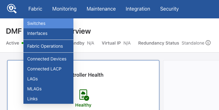
Navigate to .
Main Page
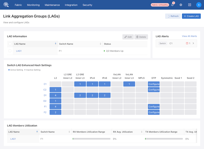
The main page contains four components:
- LAG Information
- LAG Alerts
- Switch LAG Enhanced Hash Settings
- LAG Members Utilization
LAG Information
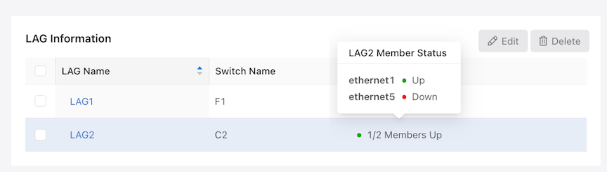
The LAG Information table displays all the LAGs configured in DMF and each member's status. A row contains the LAG Name, Switch Name, and Member Status.
Hover over a member under Status to view the status of each member interface.
Use the checkbox to Edit or Delete a LAG entry. Select the LAG Name link to open the properties tab of the LAG details panel.
Create or Edit LAG

Select Create LAG to open the configuration panel.
Enter a LAG Name and the Switch Name from the drop-down list, and choose the member Interfaces from that switch.
As an option, set the Minimum Links configuration required for the LAG to stay up. Refer to Minimum Link and Activation Configuration for Lag Interfaces for more information.
Select Submit to create the LAG.
To edit a LAG, choose it in the Information table and select Edit.
While the LAG Name and switch name are not editable, modifying member Interfaces and Minimum Links values is.
Only one LAG can be edited at a time; however, the system supports deleting multiple LAGs simultaneously.
Select Submit to commit the changes to the LAG.
LAG Alerts
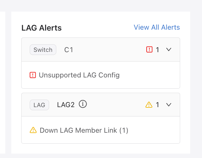
LAG Alerts displays all LAG Alerts and LAG-related Switch Alerts. The Switch or LAG tag indicates the type of alert. Expand each item to view the alert description and the number of occurrences.
LAG Enhanced Hash Grid
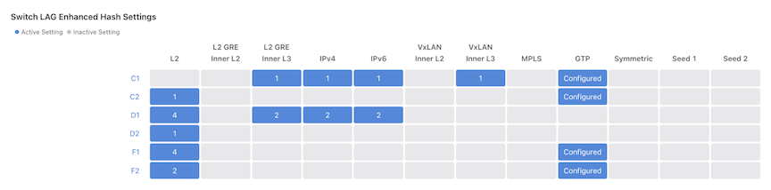
The Switch Lag Enhanced Hash Settings grid displays a switch's current LAG-enhanced hash settings across various hash fields and categories. If a cell is gray, there are no currently active sub-settings. Hover over the blue cell to view active fields. Select a switch name link to open the Enhanced Hash Configuration tab of the LAG Details pane.
LAG Members Utilization
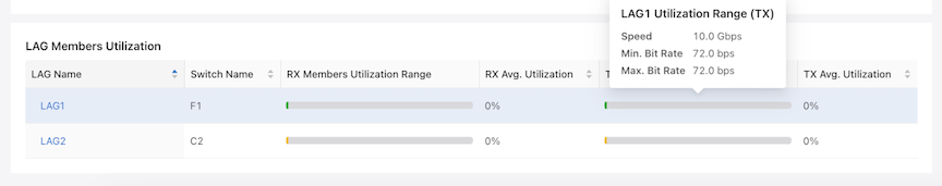
The LAG Members Utilization table summarizes the utilization for each LAG.
In the Utilization Range column, a colored bar indicates the start of the minimum utilization and the end of the maximum utilization of its members. Hover over the bar to view the Speed, minimum bit Rate, and maximum bit Rate of the LAG for each direction. The bar changes color based on LAG alerts:
- Green – indicates no alerts.
- Yellow – only warnings.
- Red – there is more than one alert.
Select the LAG Name link to open the Utilization tab of the LAG Details pane.
Details Pane
Select a LAG or switch link to open the details pane. Choose a LAG to view its details. When choosing a switch link in the Enhanced Hash grid, the first LAG on that switch is selected. If there isn't a LAG on the switch, the system displays an empty string, and the Enhanced Hash opens for that switch. The Properties and Utilization tab will be disabled. Select a different LAG to access the other tabs.
Properties
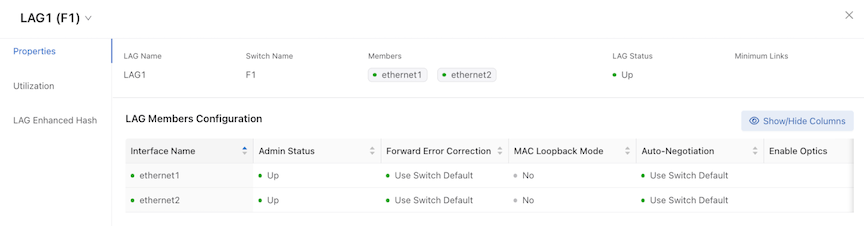
The LAG Name, Switch Name, Members tags, and Minimum Link values appear in the descriptions section. The Members Configuration table shows the configuration of each member interface. Use Show/Hide Columns to determine which columns to display.
Utilization
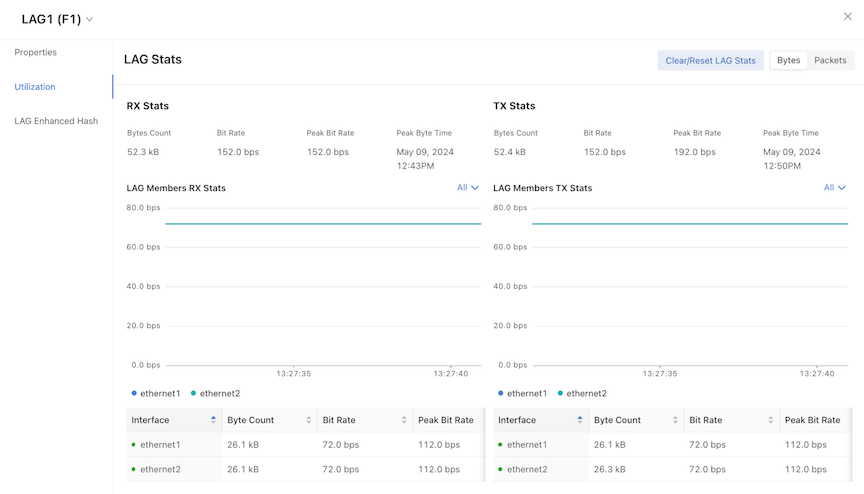
Utilization displays the utilization statistics for the LAG.
There are two time-series charts for RX and TX stats. These charts are updated every 10 seconds and display each LAG member's bit-rate / packet rate. For LAGs with over five members, select Top 5 or Bottom 5 from the All drop-down in the chart to display only the top or bottom five interfaces.
Alternate between Bytes and Packets to change the statistics displayed. Alternating between bytes and packets will not reset the time-series chart since both bytes and packet data are polled every 10 seconds.
Select Clear/Reset LAG Stats to re-initialize the chart. Selecting a new LAG re-initializes the charts, and polling begins for new LAG utilization data.
Enhanced Hash Configuration
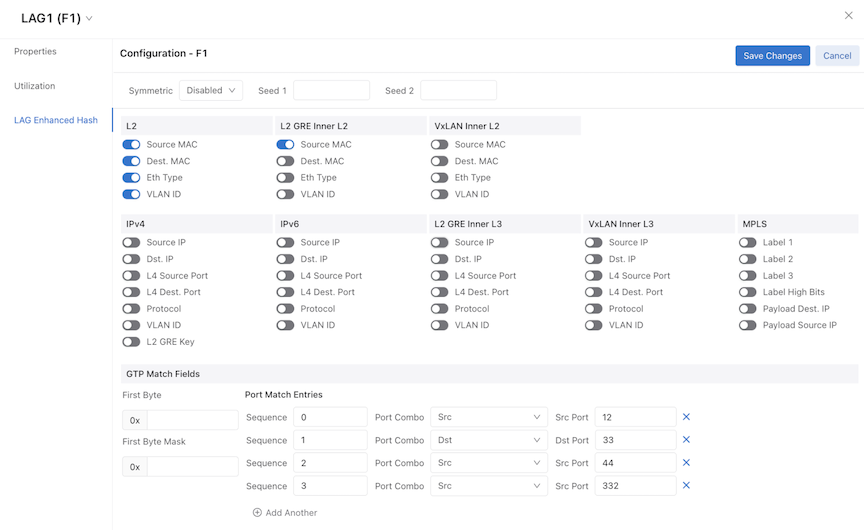
Before the DMF 8.6 release, the LAG Enhanced Hash configuration occurred on the Switches page. Now, it is done in the LAGs Detail pane.
Select Unlock to Edit to enable changing configuration settings and Save Changes to submit the changes.
The LAGs detail pane closes, and the updated settings appear in the Switch Lag Enhanced Hash Settings grid table.
Each column lists sub-settings for L2, L2 GRE Inner L2, and other configurations.
Select a link in Switch Lag Enhanced Hash Settings to turn these on and off, depending on the data required. There are validations to ensure the correct combination of settings (such as L2 GRE Inner L2 and L2 GRE Inner L3 cannot be set at the same time) that will appear in an AlertMessageList in the pane. The configuration must pass all validations to submit the changes successfully.
The Symmetric field has three options: Default, Enabled, and Disabled.
- Disable the Symmetric field for the GTP Match settings.
- Enter First Byte and First Byte Mask as hex values 0–255 with up to four Port Match Entries.
- Each port match entry must have a port combo and number values for the corresponding ports.
When setting the Port Combo to AND or OR, both Src Port and Dst Port must have non-zero values.
L2 GRE Key Hashing
Previously, L2 GRE payload-based hashing (InnerL2 or InnerL3) applied only to L2 GRE packets terminated at DMF delivery or filter switches. If a user wanted to hash L2 GRE packets transiting a DMF core switch, the L2 GRE payload-based hashing across port-channel interfaces would not have been functional as the L2 GRE tunnel was not terminating on the core DMF switch.
With the L2 GRE Key-based hashing feature, users can now hash L2 GRE packets based on the L2 GRE Key on core DMF switches.Perform the following steps:
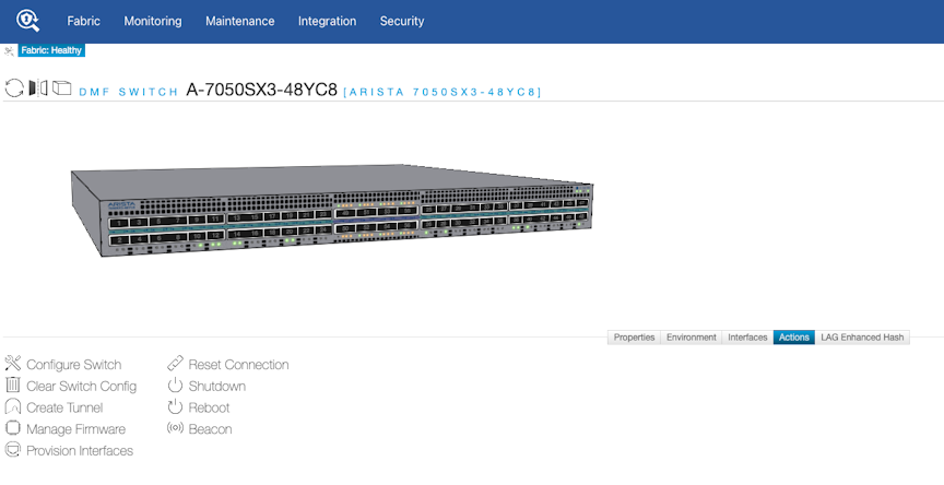
- Configure the L2 GRE Key Hashing in the UI for a switch in the page using the table row menu action Configure option.
Figure 10. Fabric Switch Configure Menu 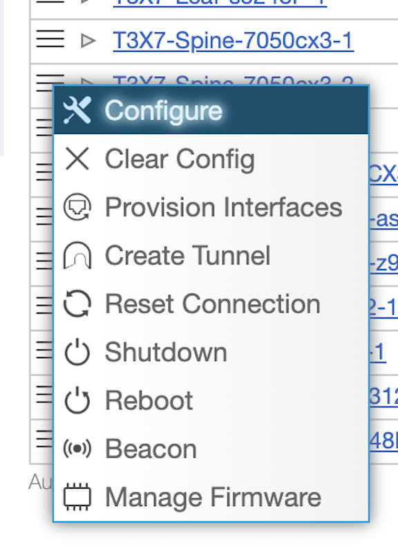
- Enable the L2 GRE Key for the IPv4 packets in the LAG Enhanced Hash step.
Note: The L2 GRE Key is unsupported for IPv6 and VXLAN Inner L3.
Figure 11. Configure Switch L2 GRE Key 
Use the CLI commands to verify settings and troubleshoot any issues that may arise.
VXLAN Hashing
Symmetric hashing works with VXLAN packet Inner L3 Source IP/Destination IP, Inner L4 Source Port/Destination Port, and Outer L3 Source IP/Destination IP.
Perform the following steps:
- Configure the VXLAN Hashing in the UI for a switch in the page using the table row menu action Configure option.
Figure 12. Fabric Switch Configure Menu - In the LAG Enhanced Hash step, configure the following fields depending on your requirements:
- L2 VXLAN Inner L2 fields
- VXLAN Inner L3 fields
Note:- L2 GRE Key is not supported for VXLAN hash fields.
- Cannot simultaneously specify enhanced hash for L2 GRE Inner L2 and Inner L3.
- Cannot simultaneously specify enhanced hash for VXLAN Inner L2 and Inner L3.
Figure 13. Configure Switch LAG Enhanced Hash 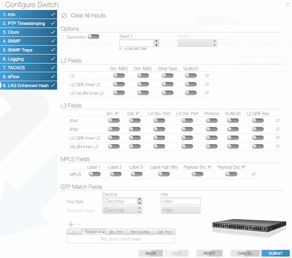
Use the CLI commands to verify settings and troubleshoot any issues that may arise.
MLAG RTAG7 Hash Computation for Unbalanced Load Balancing
In DANZ Monitoring Fabric (DMF), all SWL OS switches with the same underlying ASIC have the same RTAG7 hash parameters configured by default. After configuring MLAG to load balance traffic from filter to delivery switches, and when the number of interfaces in the MLAG and LAG in the delivery switch is the same, the traffic will not be load balanced in the delivery switch because of hash polarization.
Use the feature to avoid LAG hash polarization by choosing different hash algorithms in separate switches. The other option is using a different packet field set in each switch.
The feature supports using different hash algorithms by choosing different hash seed values.
Perform the following steps:
From the home page, select the switches using .
A list of available switches displays.
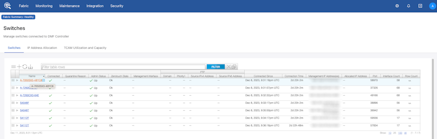
Choose the required switch for configuring the hash seeds. Hash seeds are integers used to generate random numbers in the RTAG7 hash algorithm.
Select Actions from the menu.

On the Configure Switch page, select LAG Enhanced Hash.
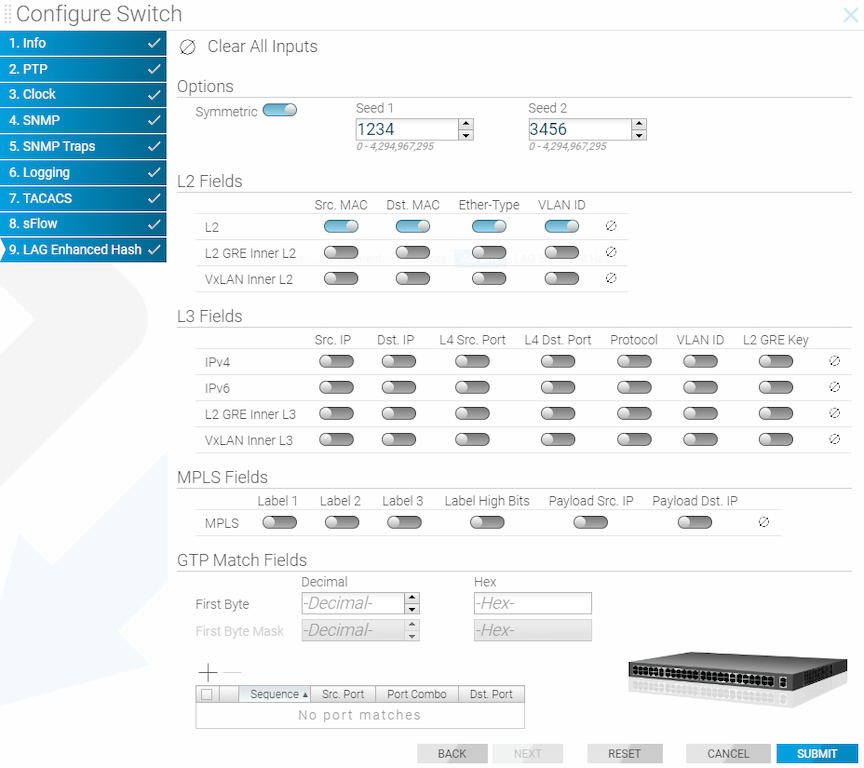
- Options
- Symmetric
- L2 Fields
- Src. MAC
- Dst. MAC
- Ether-Type
- VLAN ID
Optional: View the configured hash seed using the CLI and the following show command.
R450-C1# show lag-enhanced-hash
~~~~~~~~~~~~~~~~~~~~~~~~~~~ L2 Enhanced Hash  ~~~~~~~~~~~~~~~~~~~~~~~~~~~
# Switch DPID     Dst mac Eth type Src mac Vlan id Seed1 Seed2 Symmetric
-|---------------|-------|--------|-------|-------|-----|-----|---------|
1 A-7050SX3-48YC8 True    True     True    True    1234  3456  True
Trident4 LAG Hashing for L2GRE and VXLAN Traffic
Overview
For L2GRE transit traffic, LAG hashing uses only the encapsulated (inner) packet header fields. There is no option to use underlay (outer) packet header fields.
- When the encapsulated packet is IP, the system uses the IP parameters configured with
hash ipv4orhash ipv6for hashing. - When the encapsulated packet is L2, the system uses L2 parameters configured using
hash l2for hashing.
For VXLAN transit traffic, LAG hashing uses only the underlay packet header fields. There is no option to use encapsulated packet header fields. The system treats VXLAN transit traffic like IP traffic.
This feature is supported on Arista 7050X4 switches.
Limitations
Like other platforms, you cannot configure VXLAN and L2GRE packet fields for LAG hashing. For 7050X4 switches, the system does not support LAG configurations hash
l2gre, hash vxlan, hash ipv4, and l2-gre-key.
Pseudo Multi-Chassis Link Aggregation
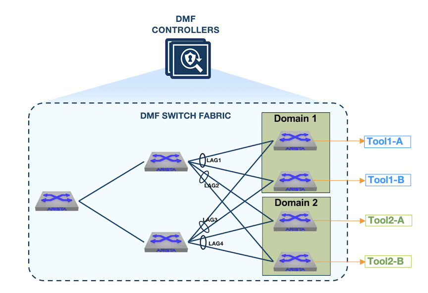
DMF supports Link Aggregation Groups (LAGs) that allow 2 or more physical interfaces on the same DMF switch to be aggregated into 1 logical interface to increase the aggregate bandwidth and provide link redundancy against link failure. This feature works well if all the tools connect to the same DMF delivery switch, typically when co-locating customer tools in the same physical location. However, in cases where tools reside in different data centers or physical locations, where a single DMF switch cannot connect to all the tools, load balancing across two DMF delivery switches is required.
A pseudo-multi-chassis Link Aggregation Group (MLAG) provides redundancy for each delivery switch connected to a multi-homed tool. With MLAG, traffic is hashed on the upstream DMF switch across two active-active links toward the delivery switches. If one of the switches fails, the traffic will fail over to the healthy switch.
MLAG Components
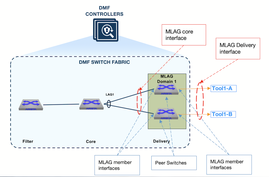
- MLAG Domain: An MLAG domain is a logical grouping of two delivery switches that will participate in an MLAG.
- Peer Switch: Member switches added into the MLAG domain.
- MLAG Interface: An MLAG interface, configured under the MLAG domain, is a logical binding of two physical interfaces or LAG interfaces, one from each peer switch.
- Core MLAG Link: A fabric-facing MLAG link. A core switch LAG interface, whose members connect to the two peer switches participating in the MLAG domain.
- Delivery MLAG Link: An MLAG interface that is assigned the delivery interface role. This interface is used in a policy as a delivery interface.
- MLAG Member Interface: A physical interface or a LAG interface added into an MLAG interface.
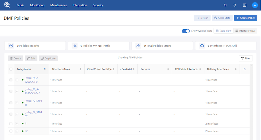
- DMF Policy: A user-configured DMF policy that contains at least one MLAG delivery interface.
- Dynamic MLAG Domain Policy: Dynamically configured policies that follow the naming convention
_mlag_DMF-policy_DeliverySwitch. For one user-configured MLAG policy, a policy that uses at least one MLAG delivery interface, two dynamic MLAG domain policies are created, one for each peer switch.
MLAG Limitations
- An MLAG domain cannot have more than two switches.
- A switch can only be a part of one MLAG domain.
- An MLAG interface can only have two member interfaces.
- An MLAG interface can only have one interface (physical interface or LAG interface) from each peer switch.
- Tunnel interfaces are not supported as members in MLAG interface configuration.
Configure MLAG
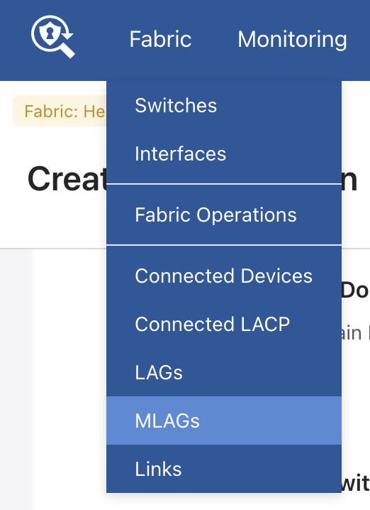
To configure an MLAG domain from the GUI, go to the tab.
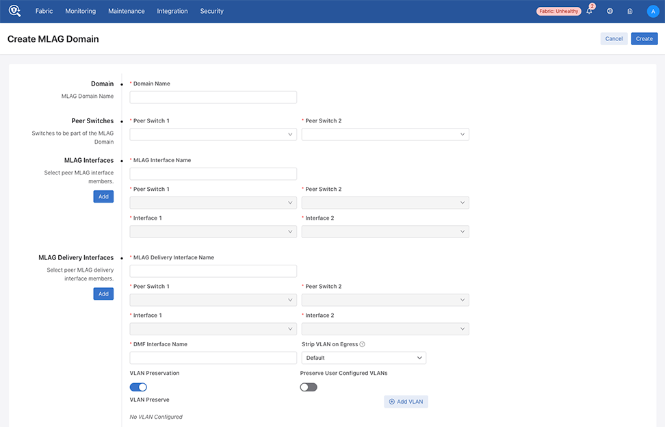
Select Create MLAG Domain and enter the following:
- Domain Name: Enter the MLAG domain alias.
- Peer Switch 1: From the drop-down, select the first switch that will be participating in the MLAG domain.
- Peer Switch 2: From the drop-down, select the second switch that will be participating in the MLAG domain.
- MLAG Interfaces: Enter an alias for the fabric-facing MLAG interface. This interface connects the core switch to the peer switches in the MLAG domain.
- Peer Switch 1 and Peer Switch 2: After selecting peer switches under the domain name, the peer switches under the MLAG interface will automatically be selected.
- Interface 1: Select the member interface that connects the core switch to DeliverySwitch-1
- Interface 2: Select the member interface that connects the core switch to DeliverySwitch-2.
- MLAG Delivery Interfaces: Enter an alias for each MLAG delivery interface.
- DMF Interface Name: Enter the DMF interface name for the MLAG delivery interface. This alias will be used to identify the delivery interface while configuring the DMF policy.
- Strip VLAN on Egress: Select the strip VLAN configuration for the MLAG delivery interface
- Peer Switch 1 and Peer Switch 2: These will be automatically selected based on the peer switches selected under the domain name.
- Interface 1: Select the member interface on Peer Switch 1.
- Interface 2: Select the member interface on Peer Switch 2.
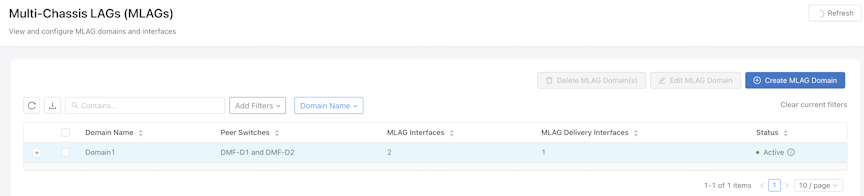
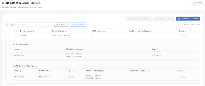
The above screenshot displays the MLAG domain status. Select + to expand each MLAG interface's domain configuration and status of each MLAG interface.
Create MLAG Policy
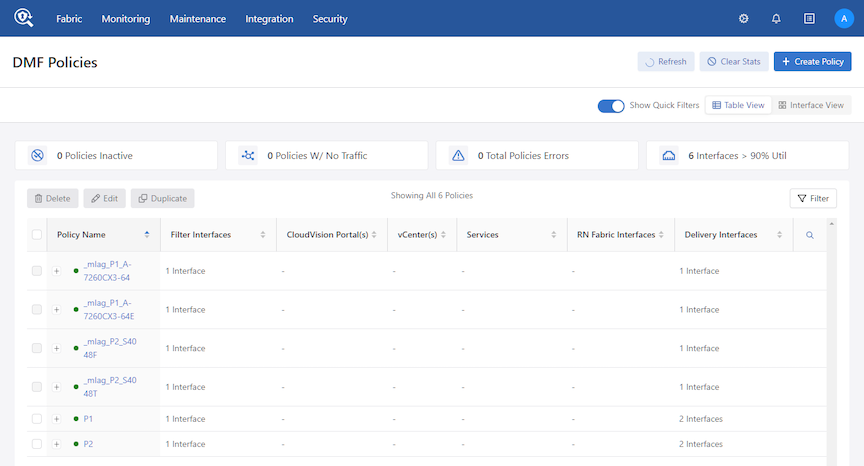
Select + Create Policy to add a new policy.
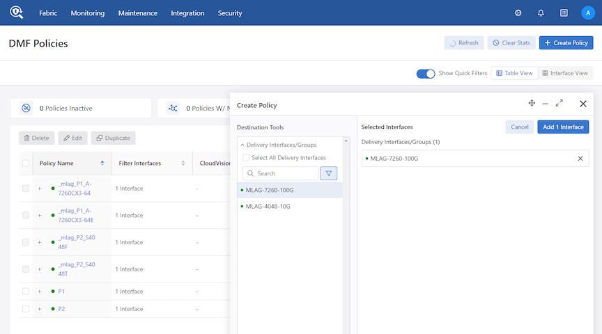
Select Add 1 Interface and enter the following to configure the policy association.
- Name: Assign a unique name to the policy.
- Description: A description for the policy.
- Action: Forward (default), None, Capture, or Drop.
- Priority: 100 (default), or enter a value.
- Scheduling: Automatic (default), Now, Set Time, or Set Delay.
- : Select the filter interface (traffic source) for the policy.
- : Specify the traffic rule for the policy.
Select Create Policy.
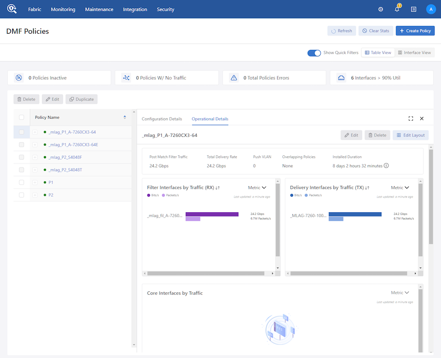
Viewing Policy Statistics
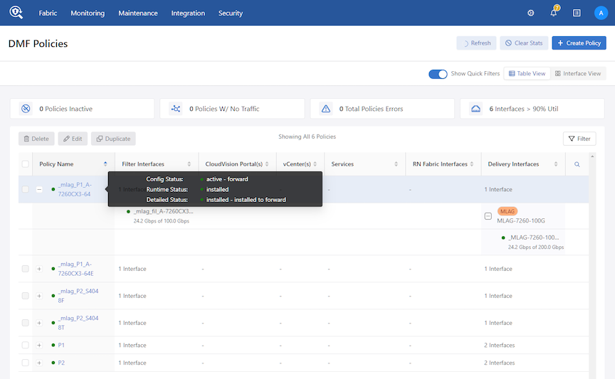
Viewing MLAG Links
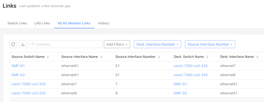
The above screenshot shows the MLAG links established between the core switch and the peer switches that are part of the MLAG domain. The LLDP message exchange discovers the links.
Using the Command Line Interface
Configure Link Aggregation Groups
Minimum Link and Activation Configuration for LAG Interfaces
Tunnel Endpoint for vCenter Integration
VXLAN LAG Hashing on DCS7280 Platforms
Configure Link Aggregation Groups
Configuring Hashing Fields
To configure the hashing fields manually via the CLI, use the lag-enhanced-hash command to enter config-switch-hash mode as in the following example:
controller1(config)# switch DMF-FILTER-SWITCH-1
controller1(config-switch)# lag-enhanced-hash
controller1(config-switch-hash)#
- To hash on GTP fields, use one of the following options:
controller1(config-switch-hash)# hash gtp
header-first-byte Configure fields to identify GTP traffic
port-match Configure UDP tunnel port match entry
- To hash on IPv4 fields, use one of the following options:
controller1(config-switch-hash)# hash ipv4
<cr>
dst-ip Destination IPv4 address (optional)
l4-dst-port TCP/UDP destination port (optional)
l4-src-port TCP/UDP source port (optional)
protocol IP protocol (optional)
src-ip Source IPv4 address (optional)
vlan-id Vlan Id (optional)
- To hash on IPv6 fields, use one of the following options
controller1(config-switch-hash)# hash ipv6
<cr>
dst-ip Collapsed destination IPv6 address (optional)
l4-dst-port TCP/UDP destination port (optional)
l4-src-port TCP/UDP source port (optional)
nxt-hdr Next Header (optional)
src-ip Collapsed source IPv6 address (optional)
vlan-id Vlan Id (optional)
- To hash on Layer-2 fields, use one of the following options:
controller1(config-switch-hash)# hash l2
dst-mac Destination xMAC address
eth-type Ethernet Type
src-mac Source MAC address
vlan-id Vlan Id
- To hash on L2GRE fields, use one of the following options:
controller1(config-switch-hash)# hash l2gre
inner-l2 Use inner L2 fields for hash computation (optional)
inner-l3 Use inner L3 fields for hash computation (optional)
- To hash on MPLS labels, use one of the following options:
controller1(config-switch-hash)# hash mpls
<cr>
label-1 Lower 16 bits of MPLS label 1 (optional)
label-2 Lower 16 bits of MPLS label 2 (optional)
label-3 Lower 16 bits of MPLS label 3 (optional)
label-hi-bits Higher 4 bits of MPLS Labels 1,2 and 3 (optional)
- To manually configure the hash seeds:
controller1(config-switch)# hash seeds
<First hash seed> Configure seed1 for hash computation
controller1(config-switch-hash)# hash seeds 3809
<cr>
<Second hash seed> Configure seed2 for hash computation (optional)
controller1(config-switch-hash)# hash seeds 3809 90901
<cr>
- To enable or disable symmetric hashing:
controller1(config-switch-hash)# hash symmetric
<cr>
disable Disable symmetric hashing
enable Enable symmetric hashing
Minimum Link and Activation Configuration for LAG Interfaces
When some LAG member links go down, it may be preferable to isolate the filter switch by bringing down the entire LAG interface rather than delivering unreliable data to tools and devices.
Two additional commands are part of the DANZ Monitoring Fabric (DMF) lag-interface configuration to aid in managing the LAG interface when a specified number of links go down. These commands are:
minimum-linkactivate
minimum-link
The minimum-link command configures the minimum number of links that must be up for a functional LAG. If the total number of active links in the interface-group is less than the configured minimum threshold, DMF brings down all active links belonging to the interface group.
The minimum-link command is optional, with a default value of 0. You should ensure this value is reasonable. If the value exceeds the total member links, the LAG will always be down.
activate
You must use the activate command to manually try to bring up the LAG if it was shut down because the number of active links was below the minimum link.
activate command to re-enable the LAG, it will go back down if the active members are still less than the minimum links value.Configuration
The minimum-link and activate commands are available within a switch's lag-interface submode. The following example illustrates configuring these options:
Use the CLI to enter the switch's submode.
- Enter the lag interface submode by using the
lag-interfacecommand. - Use the
minimum-linkcommand to configure the minimum threshold value needed before bringing down a LAG. - Use the
activatecommand to bring back up the previously shutdown LAG (due to having fewer active member links than the minimum threshold).
dmf-controller-1(config)# switch s1
dmf-controller-1(config-switch)# lag-interface lag1
dmf-controller-1(config-switch-lag-if)# minimum-link 2
dmf-controller-1(config-switch-lag-if)# activate
Show Commands
While in the switch and lag-interface submodes, the show running-config and show
this commands list the configured minimum-link threshold value. However, since activate is an action command rather than a configuration value, it doesn't appear when running the show commands.
dmf-controller-1# show running-config switch core1 lag lag1
! switch
switch core1
 !
 lag-interface lag1
 member a
 member b
 member c
 member d
 minimum-link 2
Troubleshooting
- If a LAG always shows down, ensure the
minimum-linkvalue is not greater than the total number of member links in that LAG.
Limitations
- The system doesn’t provide any warning when the
minimum-linkvalue exceeds the total number of member links in that LAG.
Tunnel Endpoint for vCenter Integration
This feature supports using Link Aggregation Group (LAG) in the tunnel endpoint configuration and runs on DANZ Monitoring Fabric (DMF) compatible switches supporting LAGs. Refer to the DMF 8.6 Hardware Compatibility Guide to view the list of compatible switches.
Configuration
Add the configured LAG as an interface in the tunnel endpoint configuration, as shown in the following example.
dmf-controller-1(conf)# tunnel-endpoint tep1 switch swl-leaf-RU35 lag1 ip-address 192.168.199.254 mask 255.255.255.0 gateway 192.168.199.1
Show Commands
Review the tunnel endpoint configuration using the following command:
dmf-controller-1# show running-config tunnel-endpoint

! tunnel-endpoint
tunnel-endpoint tep1 switch swl-leaf-RU35 lag1 ip-address 192.168.199.254 mask 255.255.255.0 gateway 192.168.199.1
Limitations
- Do not use LAG members as a Tunnel endpoint interface.
- Do not configure multiple gateways for the same interface used in Tunnel endpoints.
- Do not use a LAG configured as management or DMF interface (filter or delivery) in the Tunnel endpoint configuration.
L2 GRE Key Hashing
L2 GRE Key-based hashing is supported only for the IPv4-based packets with L2 GRE payload. This feature does NOT support the IPv6 packets with L2 GRE payloads.
Enable the L2 GRE Key hashing by setting the l2-gre-key parameter, as shown in the following example.
Controller-Active# show running-config switch DMF-SWITCH-1
! switch
switch DMF-SWITCH-1
mac c0:d6:82:17:fd:5a
!
lag-enhanced-hash
hash ipv4 l2-gre-key
hash symmetric disable
# show lag-enhanced-hash
While logged into a switch, use the following commands to troubleshoot this feature.
root@DMF-SWITCH-1:~# ofad-ctl gt PORT_CHANNEL_ENHANCED_HASH_FIELD
Hash Field Configs:
-------------------
Symmetric Hashing:
Disabled
L2GRE Key Hashing:
Enabled
L2 Fields:
IPv4 Fields:
DSTL4 SRCL4
IPv6 Fields:
MPLS Fields:
L2GRE L2 Fields:
L2GRE L3 Fields:
VXLAN L2 Fields:
VXLAN L3 Fields:

root@DMF-SWITCH-1:~# ofad-ctl bshell getreg RTAG7_HASH_CONTROL_L2GRE_MASK_A
RTAG7_HASH_CONTROL_L2GRE_MASK_A.ipipe0[1][0x6a001900]=0xffffffff
: <L2GRE_TUNNEL_GRE_KEY_MASK_A=0xffffffff>

root@DMF-SWITCH-1:~# ofad-ctl bshell getreg RTAG7_HASH_CONTROL_L2GRE_MASK_B
RTAG7_HASH_CONTROL_L2GRE_MASK_B.ipipe0[1][0x6a001a00]=0xffffffff
: <L2GRE_TUNNEL_GRE_KEY_MASK_B=0xffffffff>

root@s5248f-1:~# ofad-ctl bshell getreg RTAG7_L2GRE_PAYLOAD_L2_HASH_FIELD_BMAP
RTAG7_L2GRE_PAYLOAD_L2_HASH_FIELD_BMAP.ipipe0[1][0x6a001b00]=0: <
L2GRE_PAYLOAD_L2_BITMAP_B=0,L2GRE_PAYLOAD_L2_BITMAP_A=0>

root@s5248f-1:~# ofad-ctl bshell getreg RTAG7_L2GRE_PAYLOAD_L3_HASH_FIELD_BMAP
RTAG7_L2GRE_PAYLOAD_L3_HASH_FIELD_BMAP.ipipe0[1][0x6a001c00]=0: <
L2GRE_PAYLOAD_L3_BITMAP_B=0,L2GRE_PAYLOAD_L3_BITMAP_A=0>
root@DMF-SWITCH-1:~#
VXLAN Hashing
VXLAN hashing enables hashing on a VXLAN payload, including hashing on the Inner L3 Source IP, Inner L3 Destination IP, Inner L2 Source MAC, and inner L2 Destination MAC. This only applies to terminated cases.
Symmetric hashing works with VXLAN packet Inner L3 Source IP/Destination IP, Inner L4 Source Port/Destination Port, and Outer L3 Source IP/Destination IP.
VXLAN hashing includes hashing on L2 and L3 and the setting of at least one parameter enabled under the switch construct on Controller CLI:
# lag-enhanced-hash
hash vxlan inner-l2 dst-mac
hash vxlan inner-l3 dst-ip
CLI Commands
Use the following CLI commands to verify settings and troubleshoot any issues that may arise.
# show lag-enhanced-hash
Use the following commands to troubleshoot this feature. For example, when the hashing happens on VXSLAN payload inner L3 Src IP.
root@DMF-SWITCH-1:~# root@mrv1:~# ofad-ctl gt PORT_CHANNEL_ENHANCED_HASH_FIELD
Hash Field Configs:
-------------------
Symmetric Hashing:
Disabled
L2 Fields:
IPv4 Fields:
IPv6 Fields:
MPLS Fields:
L2GRE L2 Fields:
L2GRE L3 Fields:
VXLAN L2 Fields:
VXLAN L3 Fields:
IP4SRC_LO IP4SRC_HI

root@mrv1:~# ofad-ctl bshell getreg RTAG7_HASH_CONTROL_4
RTAG7_HASH_CONTROL_4.ipipe0[1][0x6a000700]=3:
<VXLAN_PAYLOAD_HASH_SELECT_B=1,VXLAN_PAYLOAD_HASH_SELECT_A=1,DISABLE_HASH_VXLAN_B=0,DISABLE_HASH_VXLAN_A=0>

root@mrv1:~# ofad-ctl bshell getreg RTAG7_VXLAN_PAYLOAD_L2_HASH_FIELD_BMAP
RTAG7_VXLAN_PAYLOAD_L2_HASH_FIELD_BMAP.ipipe0[1][0x6a001d00]=0: <
VXLAN_PAYLOAD_L2_BITMAP_B=0,VXLAN_PAYLOAD_L2_BITMAP_A=0>

root@mrv1:~# ofad-ctl bshell getreg RTAG7_VXLAN_PAYLOAD_L3_HASH_FIELD_BMAP
RTAG7_VXLAN_PAYLOAD_L3_HASH_FIELD_BMAP.ipipe0[1][0x6a001e00]=0x1800c00
: <VXLAN_PAYLOAD_L3_BITMAP_B=0xc00,VXLAN_PAYLOAD_L3_BITMAP_A=0xc00>
VXLAN LAG Hashing on DCS7280 Platforms
The following information addresses Virtual Extensible LAN (VXLAN) hashing capabilities and behavior, specifically on the DCS-7280 platforms.
Platform Compatibility
There are two use cases:
- Decapsulation – Strips the VXLAN header.
- Transit – Retains the VXLAN header.
Since VXLAN Header Stripping is only supported on DCS-7280R3 platforms, the Decapsulation use case is supported only on these platforms.
The Transit use case is supported on all DCS-7280 platforms.Configuration
There are two assumptions:
- The VXLAN packet is IPv4 (outer).
- The VXLAN packet has a UDP destination port value matching the configured value (default – 4789).
For the decapsulation use case, the packet context is advanced to the start of the payload upon VXLAN parsing on ingress. Hence, you can configure normal (outer) hash fields to hash against the VXLAN payload (inner) as if the outer encapsulation has already been discarded.
> enable
# config
(config)# switch switch-name
(config-switch)# lag-enhanced-hash
Limitations
- Only IPv4 VXLAN tunnel header stripping is supported.
- Currently, it is not possible to limit VXLAN packet parsing to selected interfaces on a given switch. Configuring
strip-vxlanon any switch interface will trigger VXLAN packet parsing to be active globally on the switch. In this situation, the packet context of any ingressed VXLAN packet would be advanced to the start of its payload. As a result, policy matching and hashing behaviors will be generally affected for VXLAN packets on this switch, even for packets not subject tostrip-vxlan.
MLAG RTAG7 Hash Computation for Unbalanced Load Balancing
In DANZ Monitoring Fabric (DMF), all SWL OS switches with the same underlying ASIC have the same RTAG7 hash parameters configured by default. After configuring MLAG to load balance traffic from filter to delivery switches, and when the number of interfaces in the MLAG and LAG in the delivery switch is the same, the traffic will not be load balanced in the delivery switch because of hash polarization.
Use the feature to avoid LAG hash polarization by choosing different hash algorithms in separate switches. The other option is using a different packet field set in each switch.
The feature supports using different hash algorithms by choosing different hash seed values.
CLI Configuration
(config)# switch S4048T
(config-switch)# lag-enhanced-hash
(config-switch)# hash symmetric enable
(config-switch-hash)# hash seeds 1234 3456
(config-switch-hash)# hash l2 dst-mac
(config-switch-hash)# hash l2 src-mac
(config-switch-hash)# hash l2 eth-type
(config-switch-hash)# hash l2 vlan-id
show command to view the configured hash seed.
R450-C1# show lag-enhanced-hash switch S4048T
~~~~~~~~~~~~~~~~~~~~~~~~~ L2 Enhanced Hash  ~~~~~~~~~~~~~~~~~~~~~~~~~
# Switch DPID Dst mac Eth type Src mac Vlan id Seed1 Seed2 Symmetric
-|-----------|-------|--------|-------|-------|-----|-----|---------|
1 S4048T      True    True     True    True    1234  3456  True
Troubleshooting a Configured Hash Seed
- Log in to the switch using the
connect switch
switch_name
command. - Use the
ofad-ctl gt PORT_CHANNEL_ENHANCED_HASH_SEEDcommand to print the seed values and the hash algorithm. - Ensure the hash algorithms differ in the switches where hash polarization occurs.
- Configure the hash seeds such that the hash algorithms are different.
R450-C1(config)# connect switch A-7050SX3-48YC8
Switch Light OS SWL-OS-DMF-8.6.x(0), 2023-12-07.09:17-42d8658
Linux A-7050SX3-48YC8 4.19.296-OpenNetworkLinux #1 SMP Thu Dec 7 09:28:30 UTC 2023 x86_64
Switch Light ZTN Manual Configuration. Type help or ? to list commands.
(ztn-config) debug bash
*****************************  WARNING  ******************************
Any/All activities within bash mode are UNSUPPORTED
This is intended ONLY for additional debugging ONLY by Arista TAC.
Please type "exit" or Ctrl-D to return to the CLI
*****************************  WARNING  ******************************
root@A-7050SX3-48YC8:~# ofad-ctl gt PORT_CHANNEL_ENHANCED_HASH_SEED
GENTABLE : port_channel_enhanced_hash_seed
GENTABLE ID : 0x0006
hash_seed_valid: true
HASH_SEED1=0x000004d2
HASH_SEED2=0x000004d2
computed hash algorithm from seed: CRC32LO
root@A-7050SX3-48YC8:~#
Configuring an MLAG
- Configure a DMF policy by following the procedure shown below:
Controller-1(config)# policy Policy-1
Controller-1(config-policy)# action forward
Controller-1(config-policy)# 1 match any
Controller-1(config-policy)# filter-interface Filter-1
Controller-1(config-policy)# delivery-interface MLAG-Tool-1
The above policy is configured using the MLAG-Tool-1 interface configured in Step 4. Configuring the policy to use an MLAG delivery interface will result in two dynamic policies, one for each peer switch. Refer to the following topology for the policy breakdown.Figure 31. MLAG Policy Breakdown 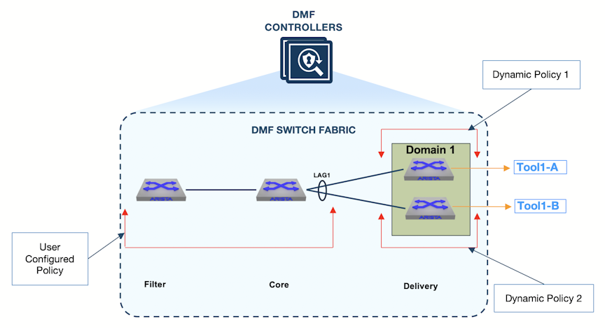
- The user-configured policy delivers traffic from the filter switch to the core switch LAG interface.
- Dynamic Policy 1 delivers traffic to delivery switch 1.
- Dynamic Policy 2 delivers traffic to delivery switch 2.
Below are the details for each policy:
- Filter Interface(s) section lists the filter interface configured for the policy, Policy-1.
- Core Interface(s) section lists the interfaces that connect the filter switch and the core switch selected for the policy.
- MLAG Core Interface(s) section displays the core LAG interface that hashes the traffic towards the peer switches.
- MLAG Delivery Interface(s) section lists the delivery MLAG interface members.
- Filter Interfaces(s) section lists the dynamically configured interface name on DeliverySwitch1 to which the core switch is connected.
- MLAG Delivery Interface(s) section lists the delivery MLAG interface member on DeliverySwitch1.
- Filter Interfaces(s) section lists the dynamically configured interface name on DeliverySwitch2 to which the core switch is connected.
- MLAG Delivery Interface(s) section lists the delivery MLAG interface member on DeliverySwitch2.
MLAG Link Discovery
Link Layer Discovery Protocol (LLDP) is used to discover MLAG links. When the DMF Controller receives an LLDP message, it looks for the switch and interface names. If the switch is a part of an MLAG domain, and the reported interface corresponds to the MLAG interface, then it is classified as an MLAG link.
Controller-1(config)# show link all link-type mlag-member
~~~~~~~~~~~~~~~~~~~~~~~~~~~~~~~~~~~~~~~~~~~~~~~~~~~~ Links ~~~~~~~~~~~~~~~~~~~~~~~~~~~~~~~~~~~~~~~~~~~~~~~~~~~~
# Active State Src switch        Src IF Name Dst switch        Dst IF Name Link Type   Since
-|------------|-----------------|-----------|-----------------|-----------|-----------|-----------------------|
1 active       CoreSwitch-1      ethernet10  DeliverySwitch-1  ethernet50  mlag-member 2022-11-11 21:54:28 UTC
2 active       CoreSwitch-1      ethernet20  DeliverySwitch-2  ethernet50  mlag-member 2022-11-11 21:54:28 UTC
3 active       DeliverySwitch-1  ethernet50  CoreSwitch-1      ethernet10  mlag-member 2022-11-11 21:54:28 UTC
4 active       DeliverySwitch-2  ethernet50  CoreSwitch-1      ethernet20  mlag-member 2022-11-11 21:54:13 UTC
Controller-1(config)#
Overlapping Policies in LAGs
An overlapping policy is dynamically configured if two configured policies share at least one filter interface and at least one of the delivery interfaces is different.
- Policy-1 uses the filter interface Filter-1 and the delivery interface MLAG-Tool-1.
- Policy-2 uses the filter interface Filter-1 and the delivery interface MLAG-Tool-2.
- The above two policies will result in an overlapping policy. An overlapping policy will be configured following the naming convention _Policy-1_o_Policy-2.
| MLAG Dynamic Policy | Parent Policy | Delivery Switch/Peer switch |
|---|---|---|
| _mlag_Policy-1_DeliverySwitch-1 | Policy-1 | DeliverySwitch-1 |
| _mlag_Policy-1_DeliverySwitch-2 | Policy-1 | DeliverySwitch-2 |
| _mlag_Policy-2_DeliverySwitch-1 | Policy-2 | DeliverySwitch-1 |
| _mlag_Policy-2_DeliverySwitch-2 | Policy-2 | DeliverySwitch-2 |
| _mlag Policy-1_o_Policy-2_DeliverySwitch-1 | _Policy-1_o_Policy-2 | DeliverySwitch-1 |
| _mlag Policy-1_o_Policy-2_DeliverySwitch-2 | _Policy-1_o_Policy-2 | DeliverySwitch-2 |
The following policies, Policy-1 and Policy-2, share the same filter interface, Filter-1, but are configured to use different delivery interfaces, MLAG-Tool-1 and MLAG-Tool-2. No priority is configured; these policies use the same default priority.
policy Policy-1
action forward
delivery-interface MLAG-Tool-1
filter-interface Filter-1
1 match ip src-ip 200.200.0.0 255.255.255.0
policy Policy-2
action forward
delivery-interface MLAG-Tool-2
filter-interface Filter-1
1 match ip dst-ip 100.100.0.0 255.255.255.0
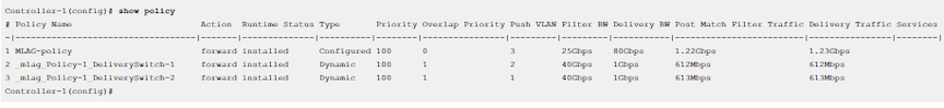
Controller-1(config)# show policy
# Policy Name            Action  Runtime Status Type       Priority Overlap Priy Push VLAN Filter BW Delivery BW Post Match Filt Traff Del Traffic Services
-|----------------------|-------|--------------|----------|--------|------------|---------|---------|-----------|----------------------|----------|--------|
1 Policy-1               forward installed      Configured      100            0         1    25Gbps      80Gbps                314Mbps    315Mbps
2 Policy-2               forward installed      Configured      100            0         3    25Gbps      80Gbps                314Mbps    315Mbps
3 _Policy-1_o_Policy-2   forward installed      Dynamic         100            1         5    25Gbps      80Gbps                314Mbps    315Mbps
- Policy-1: User-configured policy to forward packets matching source IP 200.200.0.0/24 to MLAG-Tool-1.
- Policy-2: User-configured policy to forward packets matching destination IP 100.100.0.0/24 to MLAG-Tool-2.
- _Policy-1_o_Policy-2: A dynamically configured overlapping policy with higher Overlap Priority to ensure that if a packet matches rules from both the policies (source IP of 200.200.0.1 and destination IP of 100.100.0.1), it forwards to both MLAG-Tool-1 and MLAG-Tool-2.
The following are the dynamic policies configured for each delivery switch in the MLAG Domain.

- _mlag_Policy-1_DeliverySwitch-1: MLAG dynamic policy for Policy-1 for DeliverySwitch-1.
- _mlag_Policy-1_DeliverySwitch-2: MLAG dynamic policy for Policy-1 for DeliverySwitch-2.

- _mlag_Policy-2_DeliverySwitch-1: MLAG dynamic policy for Policy-2 for DeliverySwitch-1.
- _mlag_Policy-2_DeliverySwitch-2: MLAG dynamic policy for Policy-2 for DeliverySwitch-2.
_Policy-1_o_Policy-2 Dynamic Policies

- _mlag Policy-1_o_Policy-2_DeliverySwitch-1: MLAG dynamic policy for overlapping policy for DeliverySwitch-1.
- _mlag Policy-1_o_Policy-2_DeliverySwitch-2: MLAG dynamic policy for overlapping policy for DeliverySwitch-2.
Using LAG Interfaces as Members in MLAG Interfaces
MLAG interface members can be physical interfaces or LAG interfaces to increase bandwidth. To add a LAG member to an MLAG interface, use the following procedure:
Round-Robin LAG Distribution
Link Aggregation Group (LAG) or port channel interfaces comprise multiple member interfaces. Network devices typically distribute packets across the member interfaces using a hash computed from packet header fields. The Round-Robin LAG Distribution feature introduces a new packet distribution method: round-robin. A round-robin LAG configuration balances packets evenly across all member interfaces in a sequential, round-robin fashion.
The following platforms support the Round-Robin LAG Distribution feature: Arista 7050X3, 7260X3, and Dell switches running SWL OS.
Configuration
The system supports packet distribution modes of either round-robin or hash-based (default) on a per-switch and per-LAG-interface basis. Explicit per-LAG-interface configuration overrides any per-switch configuration.
distribution-mode command provides two options: hash-based and round-robin.
dmf-controller-1(config)# switch core1
dmf-controller-1(config-switch)# distribution-mode
hash-based      Use hash-based distribution across LAG members
round-robin     Use round-robin distribution across LAG members
dmf-controller-1(config)# switch core1
dmf-controller-1(config-switch)# no distribution-mode
dmf-controller-1(config)# switch core1
dmf-controller-1(config-switch) lag-interface lag1
dmf-controller-1(config-switch-lag-if)# distribution-mode
hash-based      Use hash-based distribution across LAG members
round-robin     Use round-robin distribution across LAG members
dmf-controller-1(config)# switch core1
dmf-controller-1(config-switch) lag-interface lag1
dmf-controller-1(config-switch-lag-if)# no distribution-mode
Show Commands
dmf-controller-1> show fabric errors
~~~~~~~~~~~~~~~~~~~~~~~~~~~~~~~ Lag config not supported  ~~~~~~~~~~~~~~~~~~~~~~~~~~~~~~~
# Switch                          Unsupported Config
-|-------------------------------|------------------------------------------------------|
1 core1 (00:00:52:54:00:7b:b3:9f) Round robin hash mode is configured but not supported.
Troubleshooting
show switch all table contents lag command displays the distribution mode the Controller programs to the switches in the fabric.
dmf-controller-1> show switch all table contents lag
~~~~~~~~~~~~~~~~~~~~~~~~~~~~~~~~~~~~~~~~~~~~~~~~~~~~ Lags  ~~~~~~~~~~~~~~~~~~~~~~~~~~~~~~~~~~~~~~~~~~~~~~~~~~~~
#  Lag Device name       Entry key Entry value
--|---|-----------------|---------|---------------------------------------------------------------------------|
1  0   CORE-SWITCH-1     Port(256) Name(LAG1), HashType(BSN_HASH_TYPE_ENHANCED), Port(1), Port(2)
2  1   CORE-SWITCH-1     Port(258) Name(LAG2), HashType(BSN_HASH_TYPE_ROUND_ROBIN), Port(3), Port(4)
Limitations
-
Changing the packet distribution mode of a LAG interface between hash-based and round-robin causes a brief traffic loss.
-
A policy utilizing a round-robin LAG occasionally delivers production flow packets to the tools out of order. Round-robin distribution inherently results in out-of-order delivery. When packet ordering within a flow remains critical, the policy path from the filter to delivery interfaces must exclude round-robin LAGs.
-
Certain DMF managed services require the hashing of flows to a single Service Node interface for proper functioning. Round-robin distribution generally conflicts with the requirements of the policy path or the managed service interface for services such as IPFIX, deduplication, TCP analysis, session slicing, and flow-diff. Service actions requiring either packet delivery in the original filter interface order or flow hashing to a specific Service Node interface must not utilize round-robin at or upstream of the managed service.
-
For a single policy flow any switch on the Policy Path can support redirection to only one round-robin LAG / Interface. The addition of multiple delivery interfaces or LAGs to a policy disables round-robin hashing, in such cases every LAG on the Switch performs hash-based distribution. A policy delivering traffic to multiple round-robin LAGs / Interface on a single delivery, core, or filter switch triggers the round-robin limitation.