Installing and Upgrading the DMF Service Node
This chapter describes how to install the DANZ Monitoring Fabric DMF Service Node.
Overview
- Deduplication
- Header stripping
- IPFIX generation
- Packet masking
- NetFlow
- Pattern dropping
- Pattern matching
- Packet slicing
- Timestamping
- UDP replication
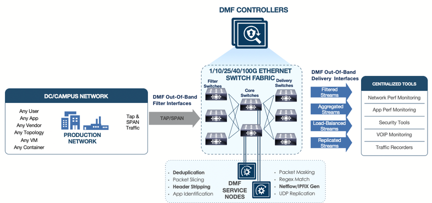
After the basic installation, the DMF Controller automatically detects each connected DMF Service Node, and the Controller starts managing the DMF Service Node Appliance along with the connected fabric switches.
For information about configuring and using the DMF Service Node, refer to the DANZ Monitoring Fabric 8.4 User Guide.
Connecting the Service Node
- Using the management interface (GbE) connected to a management switch, which provides control plane connectivity between the Service Node and the DMF controller.
- Using the Service Node data interfaces (SNI) which connect to DMF switches. For information on supported SNI interfaces, refer to the DMF Hardware Guide.
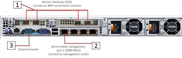
| 1 | Service Interfaces (10G) | 2 | Service Node Management Port 1 (1000 Mb/s) - Connect to the management switch. | 3 | Serial Connector |
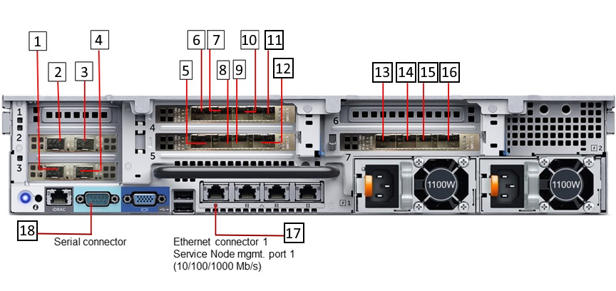
| 1 | Service interfaces SNI13 | 10 | Service interfaces SNI10 |
| 2 | Service interfaces SNI15 | 11 | Service interfaces SNI9 |
| 3 | Service interfaces SNI16 | 12 | Service interfaces SNI5 |
| 4 | Service interfaces SNI14 | 13 | Service interfaces SNI4 |
| 5 | Service interfaces SNI8 | 14 | Service interfaces SNI3 |
| 6 | Service interfaces SNI12 | 15 | Service interfaces SNI2 |
| 7 | Service interfaces SNI11 | 16 | Service interfaces SNI1 |
| 8 | Service interfaces SNI17 | 17 | Ethernet Connector 1 Service Node Management Port 1 (10/100/1000 Mb/s) |
| 9 | Service interfaces SNI6 | 18 | Serial Connector |
Service Node Setup and Initial Configuration
Complete the following steps to run the first boot setup, which performs the initial configuration required for a new DMF Service Node.
Procedure
- Once connected to the DMF Controller, it can take several minutes for Service Node to update the software.
Figure 4. Service Node software update 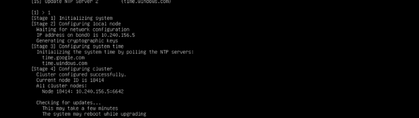
Creating Support Bundle on Service Node
The support bundle for the DANZ Monitoring Fabric (DMF) Service Node should be created from the DMF Controller (Creating a Support Bundle). But, if the DMF Service Node loses connectivity to the DMF Controller, a support bundle can be created by logging into the DMF Service Node.
The DMF Service Node CLI provides commands to automate the collecting, archiving, and uploading of critical data.
LG-SN(config)# service
LG-SN(config-service)# support auto-upload
<cr>
LG-SN(config-service)# support auto-upload
Enabled diagnostic data bundle upload
Use "diagnose upload support" to verify upload server connectivity
LG-SN(config-service)#
LG-SN(config-service)# show run service
! service
service
support auto-upload
LG-SN(config-service)#
LG-SN(config-service)# support
Generating diagnostic data bundle for technical support. This may take several minutes...
Support Bundle ID: SMFUG-BS5S2
Local cli collection completed after 32.9s. Collected 33 commands (0.14 MB)
Local rest collection completed after 0.0s. Collected 3 endpoints (0.17 MB)
Local bash collection completed after 93.3s. Collected 133 commands (6.73 MB)
Local file collection completed after 8.4s. Collected 42 paths (1851.13 MB)
Collection completed. Signing and compressing bundle...
Support bundle created successfully
00:03:16: Completed
Generated Support Bundle Information:
Name : anet-support--LG-SN--2022-04-13--07-46-01Z--SMFUG-BS5S2.tar.gz
Size : 490MB
File System Path : /var/lib/floodlight/support/anet-support--LG-SN--2022-04-13--07-46-01Z--
SMFUG-BS5S2.tar.gz
Url : https://10.240.130.8:8443/api/v1/support/anet-support--LG-SN--2022-04-
13--07-46-01Z--SMFUG-BS5S2.tar.gz
Bundle id : SMFUG-BS5S2
Auto-uploading support anet-support--LG-SN--2022-04-13--07-46-01Z--SMFUG-BS5S2.tar.gz
Transfer complete, finalizing upload
Please provide the bundle ID SMFUG-BS5S2 to your support representative.
00:01:03: Completed
LG-SN(config-service)#
The show support command shows the status of the automatic upload.
LG-SN(config-service)# show support
#  Bundle                                                               Bundle id    Size   Last modified                   Upload status
- |------------------------------------------------------------------- |----------- |----- |------------------------------ |---------------- |
1  anet-support--LG-SN--2022-04-13--07-46-01Z--SMFUG-BS5S2.tar.gz       SMFUG-BS5S2  490MB  2022-04-13 07:49:20.157000 UTC  upload-completed
2  anet-support--LG-SN--2022-04-13--07-19-08Z--SI51T-BVJJB.tar.gz       SI51T-BVJJB  488MB  2022-04-13 07:22:44.927000 UTC
3  anet-support-component--LG-SN--2021-05-19--22-47-17Z_0kc7zxw.tar.gz               462MB  2021-05-19 22:47:17.452000 UTC
LG-SN(config-service)#
diagnose upload support command to check the reachability and health of the server before uploading the support bundle.LG-SN(config-service)# diagnose upload support Upload server version: diagus-master-76 Upload diagnostics completed successfully 00:00:04: Completed Check : Resolving upload server hostname Outcome : ok Check : Communicating with upload server diagnostics endpoint Outcome : ok Check : Upload server healthcheck status Outcome : ok Check : Upload server trusts authority key Outcome : ok Check : Signature verification test Outcome : ok Check : Resolving objectstore-accelerate hostname Outcome : ok Check : Resolving objectstore-direct hostname Outcome : ok Check : Communicating with objectstore-accelerate Outcome : ok Check : Communicating with objectstore-direct Outcome : ok LG-SN(config-service)#
Upgrading Service Node Software From Release 7.x.x
Upgrading the DANZ Monitoring Fabric (DMF) Service Node, deployed in L2ZTN from DMF-7.0.0 to a later version, will be automatically completed through a zero-touch upgrade if you upgrade a DMF Release 7.0.x Controller.
Upgrade of DMF Service Node deployed in L3ZTN from DMF- 7.1.0 to a later version will be automatically completed through zero-touch when you upgrade a DMF Release 7.1.x Controller.
To verify that the Service Node is ready for the zero-touch upgrade, enter the following command from the CLI prompt on the active DMF Controller.
controller-1> show service-node sn-name zerotouch
Zerotouch status should be OK.