Using iDRAC with a Dell R430, R630, or R730 Server
This chapter provides step-by-step instructions for using the integrated Dell Remote Access Controller (iDRAC) Enterprise Version to install the DMF Controller image on Dell R430 servers and the DMF Service Node Appliance image on Dell R630 or R730 servers.
This chapter was validated using iDRAC Enterprise Version 2.10.10 and DMF Release 6.0.1. The instructions were tested with DMF Controller Release 6.0.1 on Dell R430 and DMF Service Node Appliance Release 6.0.1 on Dell R630 or R730.
To purchase an iDRAC Enterprise license, contact Dell Sales at https://www.dell.com/learn/us/en/19/campaigns/contact-us-phone-number.
Alternatively, purchase an iDRAC Enterprise license from Dell Digital Locker (DDL). https://www.dell.com/support/kbdoc/en-us/000130349/how-to-obtain-idrac-enterprise-licenses-from-dell-digital-locker-ddl.
Setting Up and Configuring iDRAC
Procedure
- Press <F2> to enter the System Setup Main Menu screen.
Figure 1. System Setup Main Menu 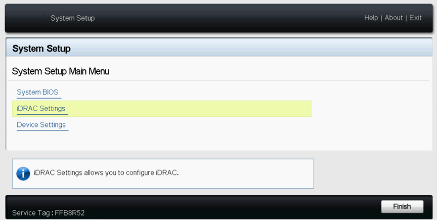
- Select iDRAC Settings from the System Setup Main Menu (F2 > iDRAC Settings).
Figure 2. iDRAC Settings 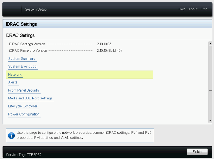
- Use the arrow keys to select Network.
Figure 3. iDRAC Settings > Network 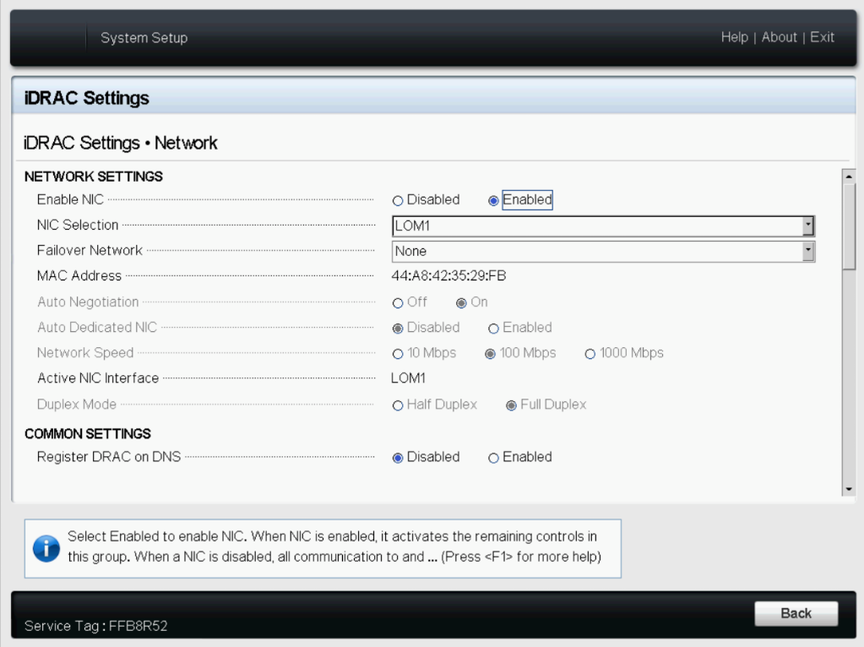
- Configure the iDRAC IPv4 address, netmask, gateway, and DNS addresses, as shown on the following page.
Figure 4. iDRAC Settings > Network (Completed Entries) 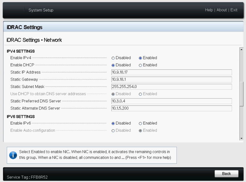
- From a web browser, type
DRAC-IPv4-addressin the browser address bar and press Enter.The system displays the iDRAC web interface.Figure 5. iDRAC Web Interface Login Window 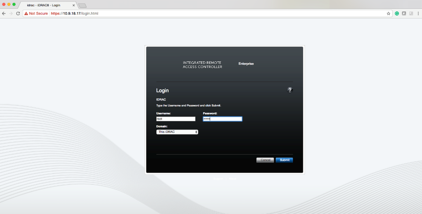
- Enter the username and password.
Default Password
By default, all PowerEdge servers ship with a unique iDRAC password, randomly generated at the factory, that is located on the pull-out Information Tag located on the front of the chassis, near the server asset tag. Customers who choose this option need to note this unique random password and use it to log in to iDRAC for the first time. For security purposes, Dell strongly recommends changing the default password.
Legacy Password
Customers who prefer to use the known legacy password calvin should choose this option. One reason to select this option would be to ensure conformance with any existing scripts. For security purposes, Dell strongly recommends changing the legacy password.
Refer to https://www.dell.com/support/kbdoc/en-us/000133536/dell-poweredge-what-is-the-default-username-and-password-for-idrac for the official Dell information.
The pull-out information card is shown in the figure below:Figure 6. Pull-out Information Card 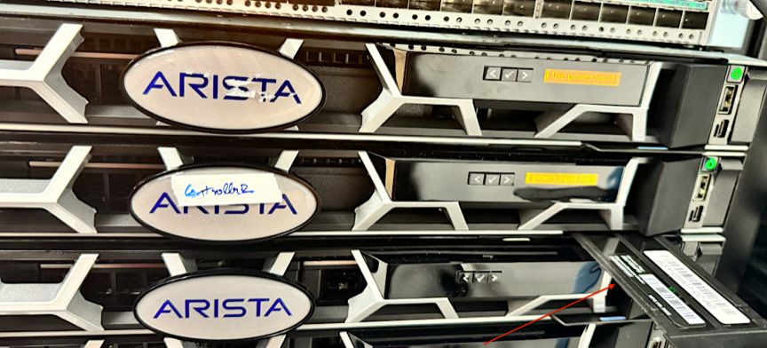 Check out the bottom label on the pull-out information card to find the default password, which in this example is 94AXYXFERKNW:
Figure 7. Default Password Location 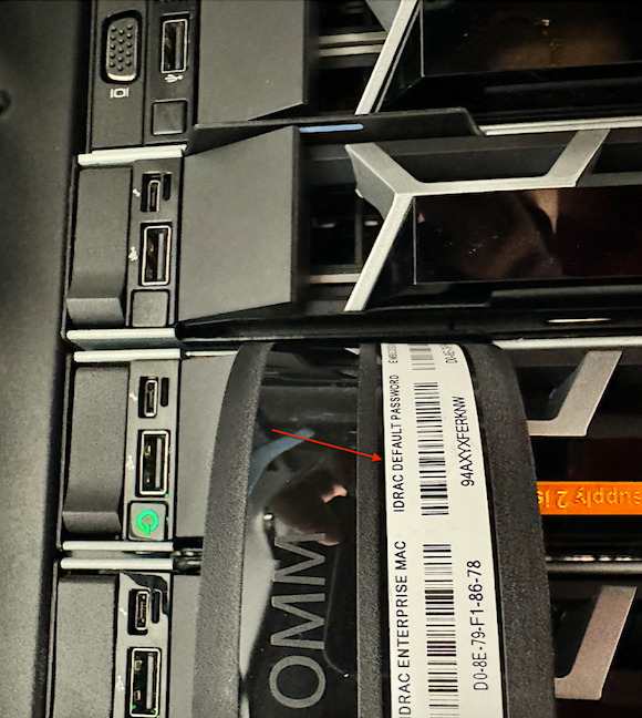
Figure 8. Change the Default Password 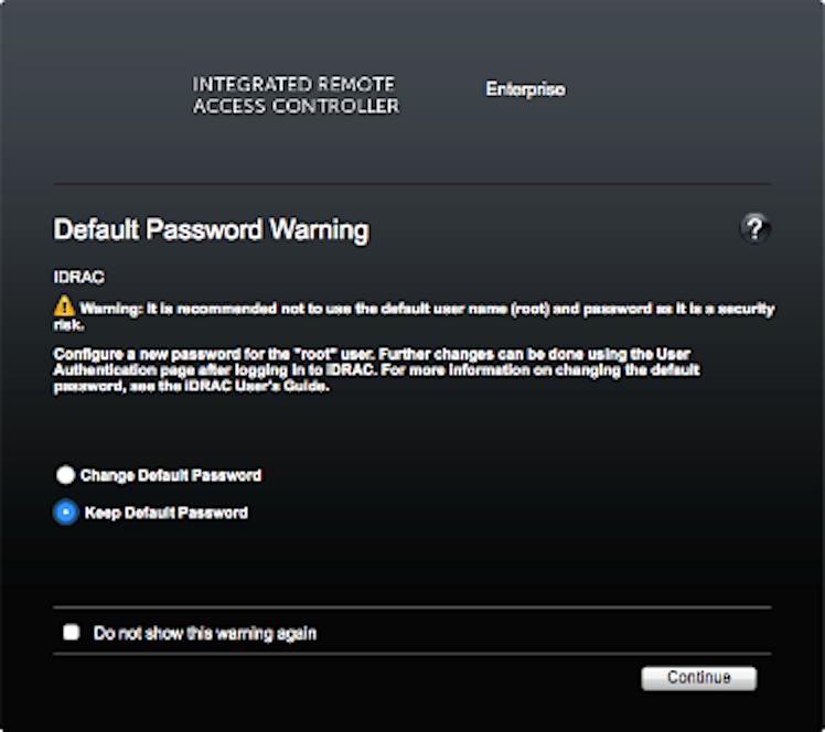
- To change the default password, type the new password, when prompted, and type it again to confirm. In this example, the password stayed the same.
Figure 9. Licensing Page 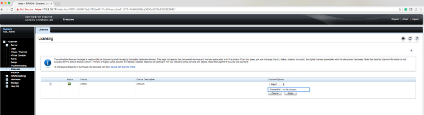
- Using the Virtual Console Preview option, click Launch.
Figure 10. System Summary Page 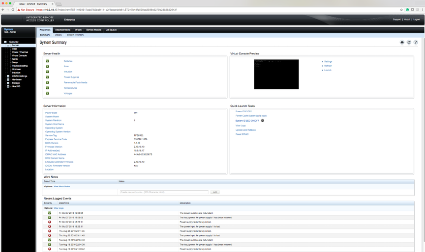
- When prompted, click Keep to confirm the operation.
Figure 11. System Summary Page 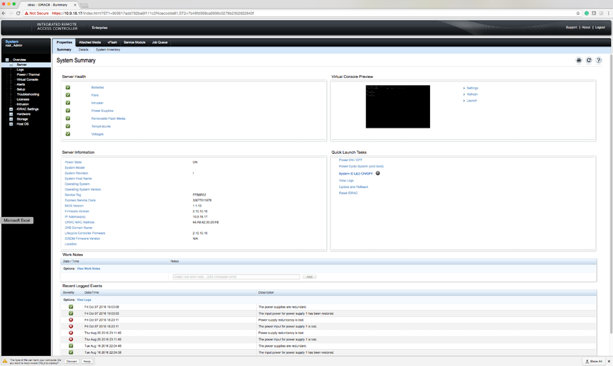
- Click the
viewer.jnlplink, as shown in the following example.Figure 12. System Summary Page 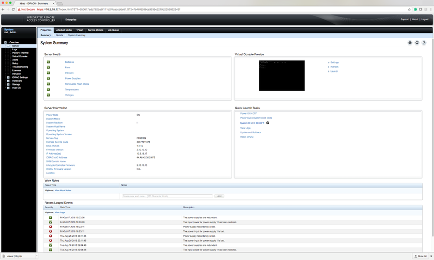
- When prompted, open the
viewer.jnlpfile.Figure 13. System Summary Page 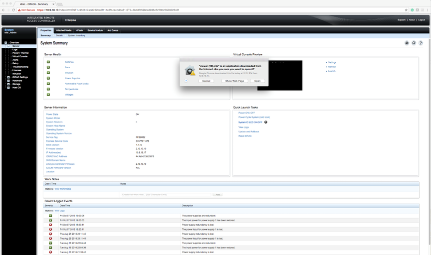 Note: JAVA is required, and the correct version downloads automatically.
Figure 14. System Summary: Continue Prompt 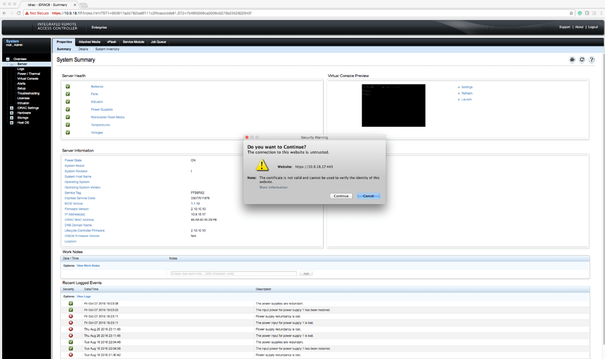
- When prompted, click Continue.
Figure 15. System Summary: Run Prompt 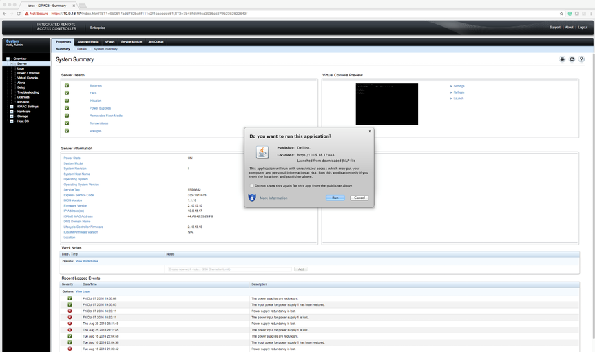
- When prompted, click Run.
Figure 16. Confirm Connection to Untrusted Network 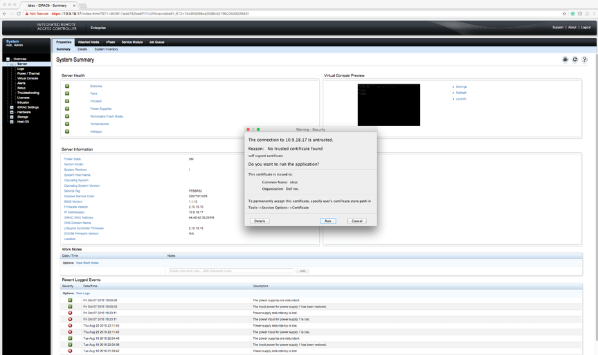
- When prompted to continue with an untrusted certificate, click Run.
Figure 17. System Summary: Confirmation Prompt 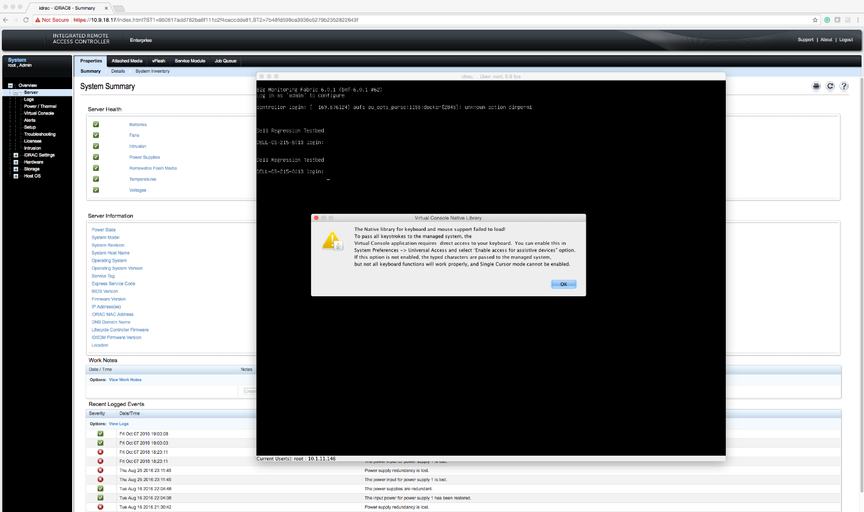
Using iDRAC to Install the DMF Controller or DMF Service Node Image
After installing the Controller software image using iDRAC, follow the instructions in Installing and Configuring the DMF Controller to complete the DMF Controller installation and initial configuration.
For DMF Release 6.3.2 onwards, the procedure for using iDRAC to install the DMF Controller or DMF Service node image is the same.
Complete the following steps using iDRAC to install the DMF Controller or Service Node image on a Dell R630/R730.
Procedure
- Direct your browser to the iDRAC web interface and log in to launch the iDRAC virtual console.
Figure 18. iDRAC Virtual Console Window 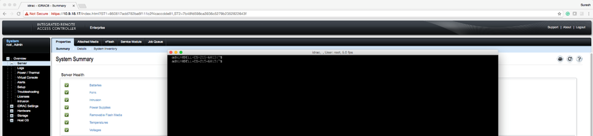
- Select .
Figure 19. Virtual Media > Connect Virtual Media Option 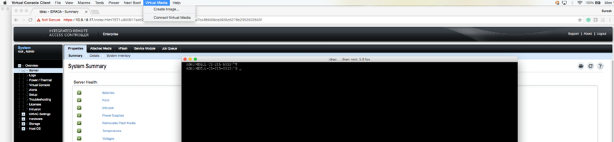
- Click Virtual Media again and select Map CD/DVD this time.
Figure 20. Virtual Media > Map CD/DVD Option 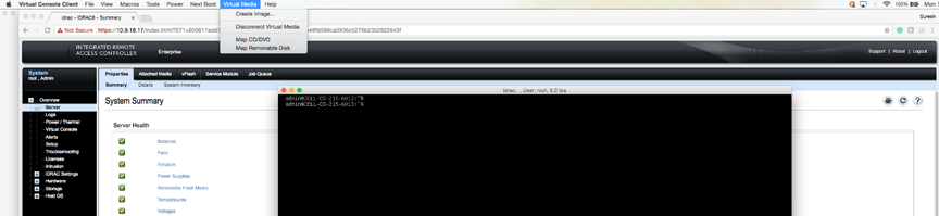
- Click Browse to choose the DMF Controller ISO file.
Figure 21. Virtual Media > Map CD/DVD Browse Option 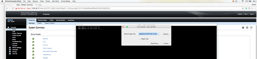
- Select the DMF Controller ISO image and click Open.
Figure 22. Open DMF Controller ISO Image 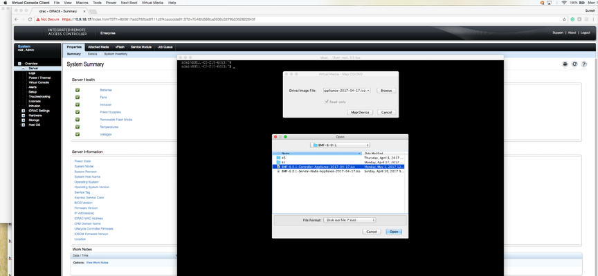
- Click Map Device.
Figure 23. Map Device 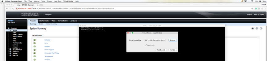
This action maps the DMF Controller ISO file to a Virtual CD/DVD on the Virtual Media menu.
Figure 24. Virtual Media > DMF Controller ISO Mapped to a Virtual CD/DVD 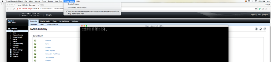
- Click Next Boot.
Figure 25. Next Boot Menu 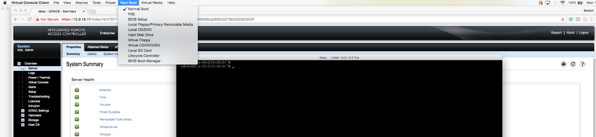
- Select Virtual CD/DVD from the Next Boot menu.
Figure 26. Next Boot > Virtual CD/DVD/ISO Option 
- When prompted, click OK.
Figure 27. Next Boot Confirmation Prompt 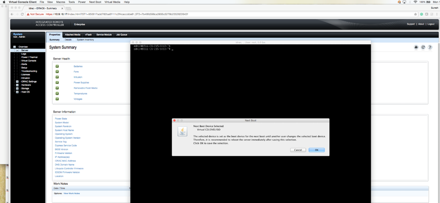
- Click Power and select Restart System (warm boot).
Figure 28. Power Restart System (warm boot) 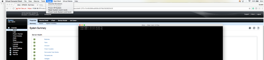
- When prompted, click OK.
Figure 29. Power Control Confirmation Prompt 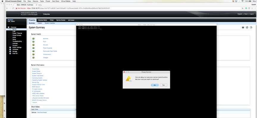 When the server boots up, it selects the Virtual CD/DVD as the boot device.
Figure 30. Booting from Virtual CD/DVD 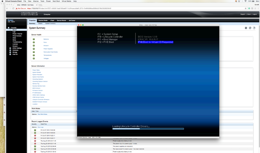 The server displays its status as it boots from Virtual CD/DVD.
Figure 31. Server Boot Status 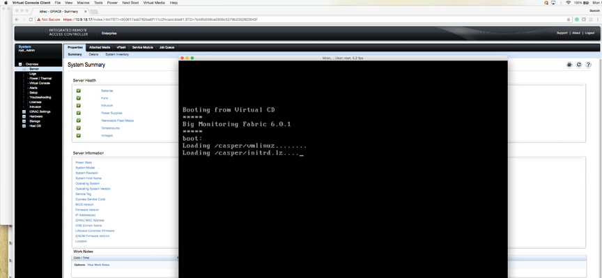 Note: Depending on the network speed, it may take a while to download the ISO image to the server.
Figure 32. Server Boot Status 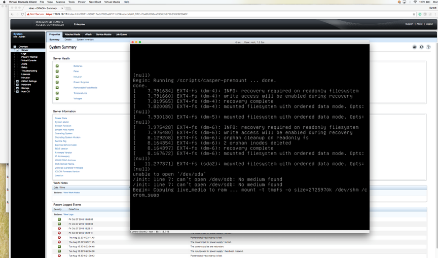
- When prompted, type yes to install the DMF Controller image on the server.
Figure 33. Installation Prompt 