Managing Switches and Interfaces
This chapter describes how to manage switches and interfaces after installing the monitoring fabric switches.
Connecting Directly to a Switch
To install the Switch Light OS individually on a switch in a different Layer 2 domain or troubleshoot the switch, use telnet or SSH to connect to the switch.
controller-1(config)# connect switch DMF-FILTER-SWITCH-1
Warning: Permanently added the RSA host key for IP address 'fe80::3617:ebff:fef2:cfc4%em1' to the
list of known hosts.
Last login: Mon Sep 18 02:32:35 2017 from fe80::46a8:42ff:fe35:29f7%ma1
SwitchLight ZTN Manual Configuration. Type help or ? to list commands.
debug admin command at the displayed ztn-config prompt.
(ztn-config) debug admin
DMF-FILTER-SWITCH-1>
- controller: adds, removes, sets, or clears the L3 ZTN Controller list
- debug: Special command to access the full switch CLI
- help: Displays CLI help
- interface: sets the ma1 address parameters
- reboot: restarts the switch
- setup: performs interactive setup
- show: displays the current settings
Manually Configuring Enhanced Hashing for Load Distribution
In some scenarios, it may be desirable to manually select the bytes in each packet that are used for load distribution among the members in a LAG.
Enter the hash-type enhanced command from the config-switch-lag-if submode to manually configure enhanced hashing.
hash command to identify the values to use for load distribution.
Changes in hash configuration do not affect the LAG configuration, so there is no need to reconfigure LAGs after changing the hash type.
Configuring Enhanced Hashing
controller-1(config-switch)# lag-enhanced-hash
controller-1(config-switch-hash)#
The hash command has the following syntax:
[no] hash gtp header-first-byte <GTP header first byte> header-first-byte-mask <GTP header first byte mask> | gtp port-match <UDP tunnel port match entry number> {dst-port <GTP tunnel UDP destination port> {and | or} src-port <GTP tunnel UDP source port> | src-port <GTP tunnel UDP source port>} | ipv4 {[dst-ip] [l4-dst-port] [l4-src-port] [protocol] [src-ip] [vlan-id]} | ipv6 {[dst-ip] [l4-dst-port] [l4-src-port] [nxt-hdr] [src-ip] [vlan-id]} | l2 [dst-mac] [eth-type] [src-mac] [vlan-id] l2gre {inner-l2 [dst-mac] [eth-type] [src-mac] [vlan-id] | inner-l3 [dst-ip] [l4-dst-port] [l4-src- port] [protocol] [src-ip] [vlan-id]} mpls {[label-1] [label-2] [label-3] [label-hi-bits] [payload-dst-ip] [payload-src-ip]} seeds { <First hash seed> [<Second hash seed>]} symmetric {enable | disable}
Symmetric Load Balancing
GTP Hashing
Generic Tunneling Protocol (GTP) hashing provides a more even distribution of GTP-encapsulated packets among the members of a port-group. When GTP hashing is enabled, DANZ Monitoring Fabric (DMF) includes the Tunnel endpoint identifier (TEID) value in the GTP packets in its hashing algorithm for outbound traffic. This applies only to GTP user data tunneling packets (udp port 2152). GTP control traffic (udp port 2123) is not affected.
hash
gtp
command. This command sets enhanced hash parameters for distributing traffic on port-channel member ports for which enhanced hashing is enabled. The command syntax is as follows:
hash gtp port-match <port-match> {dst-port <dst-port> {and | or} src-port <src-port> | dst-port
<dst- port> | src-port <src-port>}
The GTP command specifies the packet fields to identify GTP traffic. When enabled, DMF uses the TEID in the GTP header for hashing GTP traffic instead of using L4 ports—Configure l4-dst-port and l4-src-port in hash ipv4 or hash ipv6 for proper operation.
Overriding the Default Switch Configuration
- Clock
- SNMP and SNMP Traps
- Logging
- TACACS+
- override-global: Only the switch-specific configuration is applied.
- merge-global: The global config and switch-specific configuration are merged and then applied.
- Stand-alone values:If the key only exists in one of the configurations; take it as-is in the resultant configuration, otherwise:
- If the key exists in both global and switch configurations: the value of the key from the switch-config takes precedence (over its value from the global-config).
- Lists: If the list only exists in one of the configurations; take that list as-is in the result configuration, otherwise:
- If it exists in both global and per-switch configuration, then merge with this rule.
- If the global and switch-specific configuration has an entry with the same key, the switch-specific list entry completely replaces the entry from the global-config, otherwise:
- All entries from the switch-specific configuration are appended to the global-config (with de-duplication). The configurations that occur as lists for the above overridable parameters are indicated below:
- ntp
- server <- list
- time-zone
- snmp-server
- community <- list
- contact
- enable
- host <- list
- location
- switch trap
- user <- list
- logging
- controller
- remote
- remote server <- list
- tacacs
- server <- list
GUI Procedure
- To override any of the default switch configuration settings, click the Menu control next to the switch and select Configure from the pull-down menu that appears.
Figure 1. Configure Switch (Page 1) 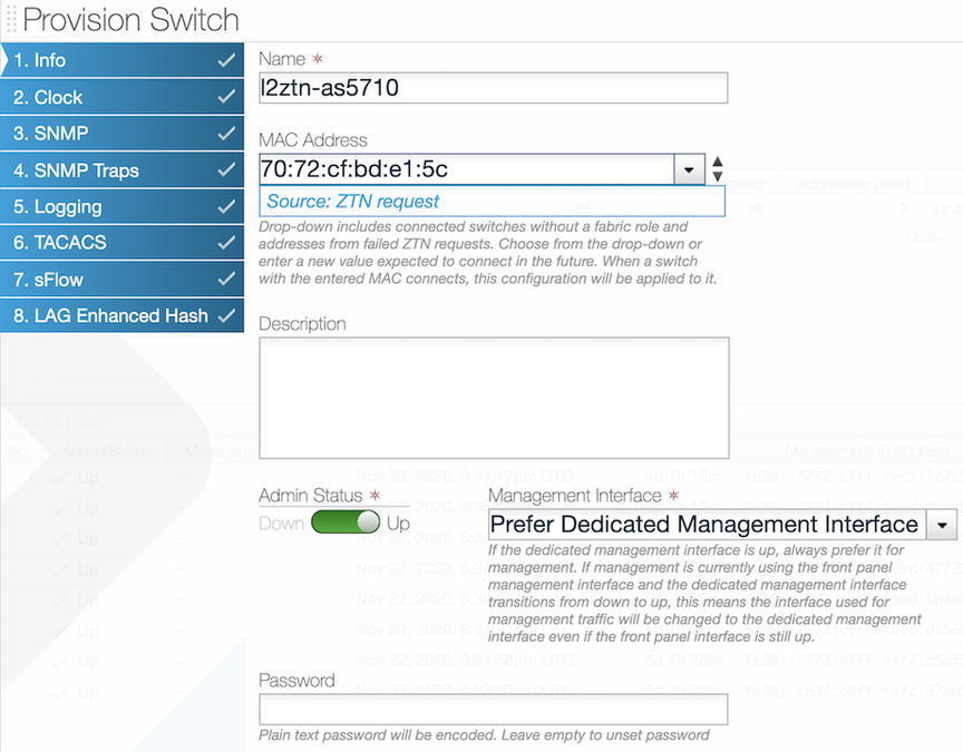 This dialog provides access to a series of dialogs used to override the default configuration that is pushed from the DMF Controller to the switch.
Configuring Switch Interfaces
Procedure
- Select from the GUI Main menu.
Figure 2. Fabric Interfaces Option 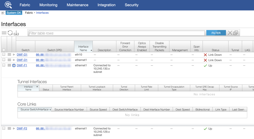 This page allows monitoring and configuring the interfaces on switches connected to the DANZ Monitoring Fabric (DMF) Controller. To display details about a specific interface, click the Expansion control to the left of the interface, and the entry expands to show any Tunnel Interfaces or Core Links currently using the interface.To configure an interface, click the Menu control next to the interface and select Configure from the pull-down menu.
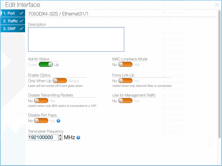
Figure 3. Configuring Interface Settings - Page 1 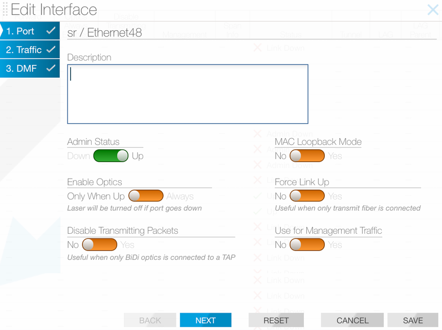 This dialog provides access to three pages.Note: Page 3 is the DMF page configuration settings for interfaces to use in policies. For further information, refer to the DANZ Monitoring Fabric User Guide.Page 1: The Port dialog provides the following options:
- Admin Status: Enable or disable the switch administratively.
- Enable Optics: Change the default to cause the optical laser to be left on after the port goes down.
- MAC Loopback Mode: Returns traffic to the originating interface.
- Force Link Up: This is useful to enable when only the transmit fiber is connected.
- Description: Assign a description for the interface.
Tip:- Ideally, only apply a force link-up configuration on a delivery interface.
- This configuration allows L1 on the port to stay up, even when the optical fiber cable is connected only in the TX direction.
- This feature helps to black hole traffic if applied on links between switches.
- When finished, click Save. To configure traffic options, click Next.
After clicking Next, the system displays the following page.Page 2:
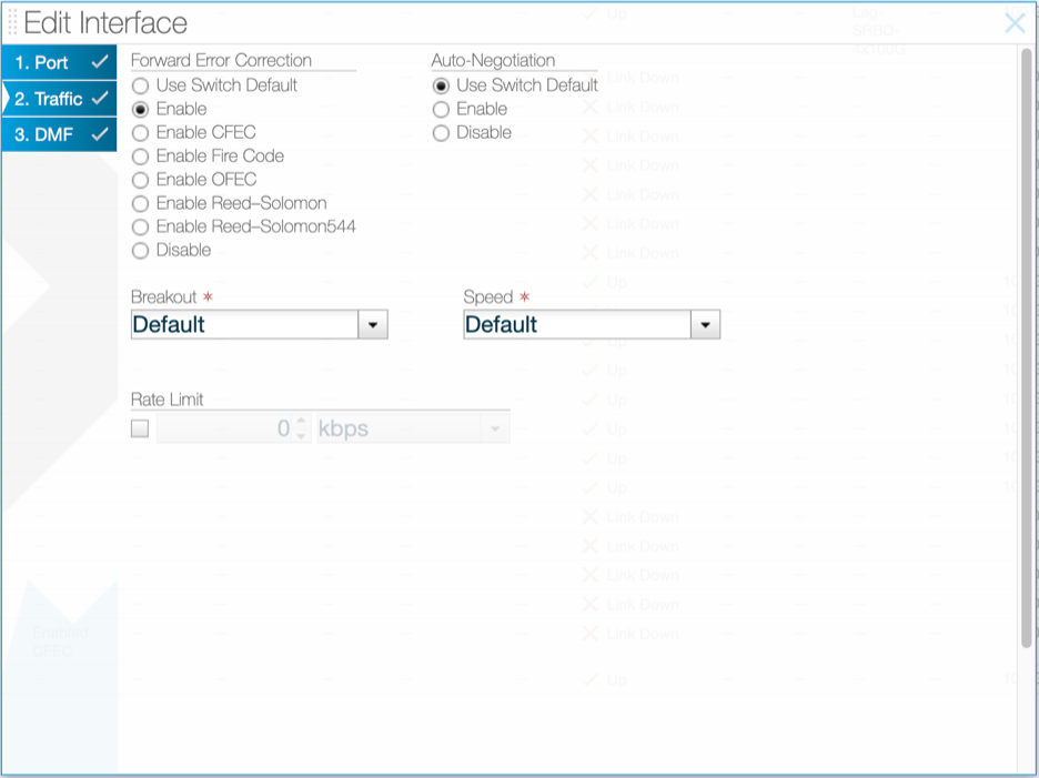
Figure 4. Configuring Interface Settings - Page 2 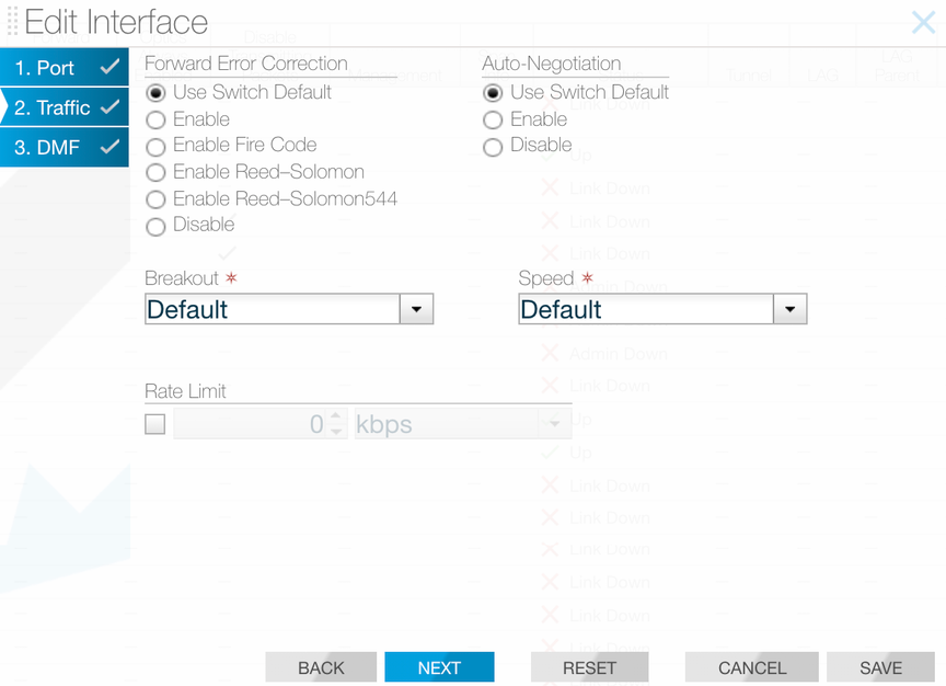 This page provides the following options.
- Forward Error Correction
- Auto-Negotiation
- Breakout
- Speed
- Rate Limit
Forward Error Correction (FEC)
Use Page 2 of the Edit Interface dialog to explicitly enable or disable forward error correction or to restore the default.
CLI Procedure
controller-1(config-switch)# interface ethernet10
controller-1(config-switch-if)# forward-error-correction
disable Force disable interface forward-error-correction
enable Force enable interface forward-error-correction
enable-fire-code Force enable interface fire-code forward-error-correction
enable-reed-solomon Force enable interface reed-solomon forward-error-correction
enable-reed-solomon544 Force enable interface reed-solomon544 forward-error-correction
controller-1(config-switch-if)# forward-error-correction enable
controller-1(config-switch-if)# show this
! switch
switch DMF-FILTER-SWITCH-1
!
interface ethernet10
autoneg disable
forward-error-correction enable
controller-1(config-switch-if)# forward-error-correction disable
controller-1(config-switch-if)# show this
! switch
switch DMF-FILTER-SWITCH-1
!
interface ethernet10
autoneg disable
forward-error-correction disable
controller-1(config-switch-if)
- disabled – Disable if possible in the current port context.
- enabled – Enable if possible in the current port context.
- enable-fire-code – Request Fire-Code FEC (CL74) in the port context.
- enable-reed-solomon – Request Reed-Solomon FEC (CL91, CL108) in the port context.
- enable-reed-solomon544 – Force Reed-Solomon544 in the port context.
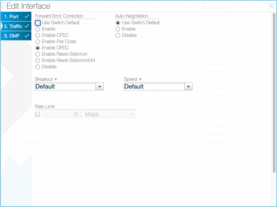
400GBASE-ZR Modules
400GBASE-ZR modules utilize coherent FEC: concatenated FEC (C-FEC) or open FEC (O-FEC), which are available amongst the FEC options in the Edit Interface window.
controller-1(config-switch)# interface ethernet31/1
controller-1(config-switch-if)# forward-error-correction
disable                    Force disable interface forward-error-correction
enable                     Force enable interface forward-error-correction
enable-cfec                Force enable interface concatenated forward-error-correction
enable-fire-code           Force enable interface fire-code forward-error-correction
enable-ofec                Force enable interface open forward-error-correction
enable-reed-solomon        Force enable interface reed-solomon forward-error-correction
enable-reed-solomon544     Force enable interface reed-solomon544 forward-error-correction

controller-1(config-switch-if)# forward-error-correction enable-ofec
controller-1(config-switch-if)# show this
! switch
switch DMF-FILTER-SWITCH-1
  !
  interface Ethernet31/1
    forward-error-correction enable-ofec
    transceiver-frequency 192100000
controller-1(config-switch-if)# forward-error-correction enable-cfec
controller-1(config-switch-if)# show this
! switch
switch DMF-FILTER-SWITCH-1
  !
  interface Ethernet31/1
    forward-error-correction enable-cfec
    transceiver-frequency 192100000
controller-1(config-switch-if)
Transceiver Frequency Configuration
All coherent transceiver modules, including 400GBASE-ZR, require their laser frequency to be explicitly configured. To configure the frequency in 400GBASE-ZR, use the transceiver frequency command under the defined interface, specifying the value in MHz in the range 191300-196100 GHz.
controller-1(config-switch-if)# transceiver-frequency
<Core/switch-config/interface/transceiver-frequency-mhz>     Enter frequency in MHz

controller-1(config-switch-if)# transceiver-frequency 193100000
controller-1(config-switch-if)# show this
! switch
switch DMF-FILTER-SWITCH-1
  !
  interface Ethernet31/1
    forward-error-correction enable-cfec
    transceiver-frequency 193100000
controller-1(config-switch-if)# transceiver-frequency 192100000
controller-1(config-switch-if)# show this
! switch
switch DMF-FILTER-SWITCH-1
  !
  interface Ethernet31/1
    forward-error-correction enable-cfec
    transceiver-frequency 192100000
controller-1(config-switch-if)
Use Page 1 of the Edit Interface dialog to configure the frequency.
Autonegotiation
- autoneg enabled – Enable if possible in the current port context.
- autoneg disabled – Disable if possible in the current port context.
- 100 GbE DAC in 100 GbE mode
- 25 GbE
- 1G-BASE-SX
- 1G-BASE-LX
GUI Procedure
Use Page 2 of the Edit Interface dialog to enable or disable autonegotiation, or to restore the default.
CLI Procedure
controller-1(config-switch)# interface ethernet10
controller-1 (config-switch-if)# autoneg enable
controller-1 (config-switch-if)# show this
! switch
switch DMF-FILTER-SWITCH-1
!
interface ethernet10 autoneg enable
controller-1 (config-switch-if)# autoneg disable
controller-1 (config-switch-if)# show this
! switch
switch DMF-FILTER-SWITCH-1
!
interface ethernet10
autoneg disable
controller-1 (config-switch-if)#
Replace intf-port-list by the interface name or port list.
Manually Setting the Interface Speed
To manually set the interface speed for an interface, from config-switch-if submode, enter the speed command, which has the following syntax.
[no] speed [{100G | 25G | 200G | 1G | 10G | 40G | 400G | 50G}]
- 100G Set interface speed to 100 Gbps
- 10G Set interface speed to 10 Gbps
- 1G Set interface speed to 1 Gbps
- 200G Set interface speed to 200 Gbps
- 25G Set interface speed to 25 Gbps
- 400G Set interface speed to 400 Gbps
- 40G Set interface speed to 40 Gbps
- 50G Set interface speed to 50 Gbps
Using Breakout Cables
For a list of supported switches, ports, and breakout cables, refer to the DANZ Monitoring Fabric 8.5 Hardware Compatibility List. The breakout cables listed in the Hardware Compatibility List are broken out automatically; manually entering the breakout command is not required.
GUI Procedure
To use the GUI to manually enable the use of multiple interfaces on a single switch port with a breakout cable, select , select Edit from the menu control for an interface, and use the settings on the Traffic page (Page 2) of the Edit Interface dialog.
To enable the use of multiple interfaces on a single switch port with a breakout cable, complete the following steps.CLI Procedure
- 2x100G Breakout to 2 sub-interfaces of 100G each
- 2x200G Breakout to 2 sub-interfaces of 200G each
- 2x40G Breakout to 2 sub-interfaces of 40G each
- 2x50G Breakout to 2 sub-interfaces of 50G each
- 4x100G Breakout to 4 sub-interfaces of 100G each
- 4x10G Breakout to 4 sub-interfaces of 10G each
- 4x1G Breakout to 4 sub-interfaces of 1G each
- 4x25G Breakout to 4 sub-interfaces of 25G each
- 4x50G Breakout to 4 sub-interfaces of 50G each
- 8x10G Breakout to 8 sub-interfaces of 10G each
- 8x25G Breakout to 8 sub-interfaces of 25G each
- 8x50G Breakout to 8 sub-interfaces of 50G each
Verifying Switch Configuration
GUI Procedure
Use the option to view the interfaces table, which provides information about the configuration and activity on each interface of the switches connected to the DANZ Monitoring Fabric (DMF) controller.
CLI Procedure
To view the configuration or activity for a specific interface, use the show
switch switchname interfaces command. The detail option provides additional information about the interface, including the up and down counts, indicating if the interface has been flapping. The output also indicates if the interface supports breakout interfaces.
controller-1# show switch DMF-DELIVERY-SWITCH-1 interfaces ethernet49 detail # IF Name MAC Address Config State Adv. Features Curr Features SupportedFeatures - |------------ |------------------------------ |------ |----- |------------------- |------------- |------------------------------- | 1 ethernet49 5c:16:c7:13:d5:d8 (Big Switch) up down fec, 25g, 50g, 100g fec fec,bsn-breakout-capable, 100g
show
switch
switchname interface description command as shown in the following example.
controller-1(config-switch-if)# show switch DMF-DELIVERY-SWITCH-1 interface description
# Switch Name           IF Name      Description
-|---------------------|------------|---------------|
1 DMF-DELIVERY-SWITCH-1 ethernet1    100g-to-SFO
2 DMF-DELIVERY-SWITCH-1 ethernet2    100g-to-NYC
Disabling the TX Direction on an Interface
Example of command usage:
dmf-controller-1(config)# switch sw-filter1
dmf-controller-1(config-switch)# interface ethernet2
dmf-controller-1(config-switch-if)# disable-xmit