Installing DMF Switches
This chapter describes installing DANZ Monitoring Fabric (DMF) switches and performing initial setup and configuration.
DMF supports secure HTTPS connectivity for Controller-hosted URLs using ZTP.
Before DMF version 8.4, the Controller used HTTP to access ZTP install scripts and software images. HTTP does not provide the security required in today’s network environments, so the need for HTTPS support arose in those customer environments where all port 80 traffic (HTTP) is blocked. Blocking HTTP access makes the DHCP-based installation of Switch Light and other required software impossible. This new feature allows access to ZTP install scripts and software images via secure HTTPS.
HTTPS Support for Controller Hosted URLs using ZTP
DANZ Monitoring Fabric (DMF) supports secure HTTPS connectivity for Controller-hosted URLs using ZTP.
Before DMF version 8.4, the Controller used HTTP to access ZTP install scripts and software images. HTTP does not provide the security required in today’s network environments, so the need for HTTPS support arose in those customer environments where all port 80 traffic (HTTP) is blocked. Blocking HTTP access makes the DHCP-based installation of Switch Light and other required software impossible. This new feature allows access to ZTP install scripts and software images via secure HTTPS.
This feature does not require any special configuration.
Use the CLI show switch-image url command to display the URLs for the ZTP install script and images.
The output contains HTTP and HTTPS URLs for the script and each available image, as shown in the following example.
C1> show switch-image url
# File                      Url                                                          Alternative Url
-|-------------------------|------------------------------------------------------------|---------------|
1 arista-ztp-install-script http://<controller IP>/switchlight/arista-ztp-install-script
2 arista-ztp-install-script https://<controller IP>/switchlight/arista-ztp-install-script
3 install-amd64             http://<controller IP>/switchlight/install-amd64
4 install-amd64             https://<controller IP>/switchlight/install-amd64
5 update-amd64              http://<controller IP>/switchlight/amd64
6 update-amd64              https://<controller IP>/switchlight/amd64
7 update-aristaeos          http://<controller IP>/eos/x86_64
8 update-aristaeos          https://<controller IP>/eos/x86_64
Chassis Support in the DMF Controller
Starting from DANZ Monitoring Fabric (DMF) release 8.7, the DMF Controller's support for modular chassis switches has been improved by adding platform compatibility with the DCS-7289-CH switches.
For DCS-7289-CH switches, the switch card module controls the chassis capabilities and no longer relies on reconciling line card ASICs by picking the least capable ASIC.
The DMF Controller now supports a new command: system reboot switch
<switch name> supervisor
<slot>. This command reboots supervisor modules.
Line card modules also provide a new port count property. They display this property per line card and at the switch level. The switch level shows properties like Max Physical Port and Max LAG components.
Platform Compatibility
DMF 8.7.0 supports the following modular switches:
-
DCS-7289-CH
Configuration
The DMF Controller provides a new command to reboot the supervisor module on a chassis, as shown below:
dmf-controller-1> enable
dmf-controller-1# system reboot switch <switch name> supervisor <slot>
DCS-7289-CH switches only have one supervisor card, so they don’t support redundancy.
Show Commands
-
The
show switch <switch> chassis
module-property
command replaces the formershow switch <switch> chassis linecard-propertycommand.The updated command output displays a
Port Countproperty showing each line card’s port count underModule Properties. For thesw-7289chassis, the switchcard module determines the capabilities of each line card. The only property reported per line card is thePort Count.dmf-controller-1> show switch sw-7289 chassis module-property ~~~~~~~~~~~~~~~~~~~~~~ Module Properties~~~~~~~~~~~~~~~~~~~~~~~~~~~~ Switch : sw-7289 Module Slot : 2 Port Count : 32 ~~~~~~~~~~~~~~~~~~~~~~ Module Properties ~~~~~~~~~~~~~~~~~~~~~~~~~~~~ Switch : sw-7289 Module Slot : 3 Port Count : 32 ~~~~~~~~~~~~~~~~~~~~~~ Module Properties ~~~~~~~~~~~~~~~~~~~~~~~~~~~~ Switch : sw-7289 Module Slot : 4 Port Count : 32 ~~~~~~~~~~~~~~~~~~~~~~ Module Properties ~~~~~~~~~~~~~~~~~~~~~~~~~~~~ Switch : sw-7289 Module Slot : 5 Port Count : 32 ~~~~~~~~~~~~~~~~~~~~~~ Module Properties ~~~~~~~~~~~~~~~~~~~~~~~~~~~~ Switch : sw-7289 Module Slot : 6 Port Count : 32 ~~~~~~~~~~~~~~~~~~~~~~ Module Properties ~~~~~~~~~~~~~~~~~~~~~~~~~~~~ Switch : sw-7289 Module Slot : 7 Port Count : 32 ~~~~~~~~~~~~~~~~~~~~~~ Module Properties ~~~~~~~~~~~~~~~~~~~~~~~~~~~~ Switch : sw-7289 Module Slot : 8 Port Count : 32 ~~~~~~~~~~~~~~~~~~~~~~ Module Properties ~~~~~~~~~~~~~~~~~~~~~~~~~~~~ Switch : sw-7289 Module Slot : 9 Port Count : 32 ~~~~~~~~~~~~~~~~~~~~~~ Module Properties ~~~~~~~~~~~~~~~~~~~~~~~~~~~~ Switch : sw-7289 Module Slot : 10 Port Count : 32 ~~~~~~~~~~~~~~~~~~~~~~ Module Properties ~~~~~~~~~~~~~~~~~~~~~~~~~~~~ Switch : sw-7289 Module Slot : Switchcard1 Tunnel Supported : BSN_TUNNEL_L2GRE,BSN_TUNNEL_DZGRE UDF Supported : BSN_UDF_6X2_BYTES Enhanced Hash Supported : BSN_ENHANCED_HASH_L2,BSN_ENHANCED_HASH_L3,BSN_ENHANCED_HASH_L2GRE,BSN_ENHANCED_HASH_MPLS,BSN_ENHANCED_HASH_SYMMETRIC PTP Timestamp Supported Capabilities : ptp-timestamp-cap-replace-smac, ptp-timestamp-cap-header-64bit, ptp-timestamp-cap-header-48bit, ptp-timestamp-cap-flow-based, ptp-timestamp-cap-add-header-after-l2 Strip Header Supported : BSN_STRIP_HEADER_CAPS_VXLAN Port Count : 0
-
The
show switch <name> chassis modulecommand reports the effectiveASICfor the switch card module, as shown below.Note: Line cards report the ASIC as aswitchcardindicating the chassis type.dmf-controller-1> show switch sw-7289 chassis module # Switch Slot Model Type ASIC --|-------|-----------|------------|----------|--------------| 1 sw-7289 2 7358-16C linecard switchcard 2 sw-7289 3 7358-16C linecard switchcard 3 sw-7289 4 7358-16C linecard switchcard 4 sw-7289 5 7358-16C linecard switchcard 5 sw-7289 6 7358-16C linecard switchcard 6 sw-7289 7 7358-16C linecard switchcard 7 sw-7289 8 7358-16C linecard switchcard 8 sw-7289 9 7358-16C linecard switchcard 9 sw-7289 10 7358-16C linecard switchcard 10 sw-7289 1 7289-SUP-S-D supervisor 11 sw-7289 Switchcard1 7289R3AK-SC switchcard jericho2c-plus
You can filter the output by module type by using the following options, as shown in the examples below:-
linecard -
supervisor -
switchcard
dmf-controller-1> show switch sw-7289 chassis module linecard
# Switch  Slot Model    Type     ASIC
-|-------|----|--------|--------|----------|
1 sw-7289 2    7358-16C linecard switchcard
2 sw-7289 3    7358-16C linecard switchcard
3 sw-7289 4    7358-16C linecard switchcard
4 sw-7289 5    7358-16C linecard switchcard
5 sw-7289 6    7358-16C linecard switchcard
6 sw-7289 7    7358-16C linecard switchcard
7 sw-7289 8    7358-16C linecard switchcard
8 sw-7289 9    7358-16C linecard switchcard
9 sw-7289 10   7358-16C linecard switchcard

dmf-controller-1> show switch sw-7289 chassis module supervisor
# Switch  Slot Model        Type
-|-------|----|------------|----------|
1 sw-7289 1    7289-SUP-S-D supervisor

dmf-controller-1> show switch switch2 chassis module switchcard
# Switch  Slot        Model       Type       ASIC
-|-------|-----------|-----------|----------|--------------|
1 sw-7289 Switchcard1 7289R3AK-SC switchcard jericho2c-plus
-
-
The
show switch <switch> propertycommand contains the following updates:-
Max Physical PortandMax Lagcomponents now appear under the switch properties, whereas previously they appeared as module properties for the chassis. -
The
Port Countvalue under the switch properties displays the sum of the port counts across all the line cards in the chassis.
dmf-controller-1> show switch sw-7289 property
Switch                               : sw-7289
Max Phys Port                        : 1000000
Min LAG Port                         : 1000001
Max LAG Port                         : 1000512
Min Tunnel Port                      : 15000001
Max Tunnel Port                      : 15001024
Max LAG Comps                        : 32
Tunnel Supported                     : BSN_TUNNEL_L2GRE,BSN_TUNNEL_DZGRE
UDF Supported                        : BSN_UDF_6X2_BYTES
Enhanced Hash Supported              : BSN_ENHANCED_HASH_L2,BSN_ENHANCED_HASH_L3,BSN_ENHANCED_HASH_L2GRE,BSN_ENHANCED_HASH_MPLS,BSN_ENHANCED_HASH_SYMMETRIC
Min Rate Limit                       : 1Mbps
Max Rate Limit                       : 400Gbps
Cpu Trap Table Supported             : False
Max Multicast Replication Groups     : 65535
Max Multicast Replication Entries    : 524280
Min Truncate Offset                  : 100
Max Truncate Offset                  : 9236
Strip Header Supported               : BSN_STRIP_HEADER_CAPS_VXLAN
PTP Timestamp Supported Capabilities : ptp-timestamp-cap-replace-smac, ptp-timestamp-cap-header-64bit, ptp-timestamp-cap-header-48bit, ptp-timestamp-cap-flow-based, ptp-timestamp-cap-add-header-after-l2
MACsec Supported Capabilities        : macsec-cap-hardware-supported
Strip VLAN on Egress Capability      : strip-one, strip-two
Port Count                           : 288
-
Limitations
-
Line card and fabric modules cannot be rebooted from the DMF Controller.
-
The DMF Controller does not report the thermal sensors for supervisors, line cards, and fabric modules.
Zero Touch Fabric Provisioning Modes
- Layer 2 Zero Touch Fabric (L2ZTF, Auto-discovery switch provisioning mode): In this mode (which was the default up to DMF release 8.4), the switch software automatically discovers the Controller via IPv6 local link addresses and downloads and installs the appropriate Switch Light OS image from the Controller. This installation method requires all the fabric switches and the DMF Controller to be in the same Layer 2 network (IP subnet). If the fabric switches need IPv4 addresses to communicate with SNMP or other external services, configure IPAM, which provides the Controller with a range of IPv4 addresses to allocate to the fabric switches.
- Layer 3 Zero Touch Fabric (L3ZTF, Pre-configured switch provisioning mode): In this mode, which is the default starting from DMF release 8.5, when fabric switches are in a different Layer 2 network from the Controller, log in to each switch individually to configure network information and download the ZTF installer. Subsequently, the switch automatically downloads Switch Light OS from the Controller. This mode requires communication between the Controller and the fabric switches to occur using IPv4 addresses, and no IPAM configuration is required.
controller-1(config)# switch <name>
controller-1(config-switch)# mac <mac-address>
controller-1(config)# switch core1
controller-1(config-switch)# mac 1234.5678.9abc
controller-1(config-switch)# show this

! switch
switch core1
  mac 12:34:56:78:9a:bc
A MAC address is always stored and presented in the colon-separated format, regardless of the address format used to enter it in the configuration.
The following table summarizes the requirements for installation using each mode:
| Requirements | Layer 2 mode | Layer 3 mode |
|---|---|---|
| Any switch in a different subnet from the Controller? | No | Yes |
| IPAM configuration for SNMP and other IPv4 services? | Yes | No |
| IP address assignment | IPv4 or IPv6 | IPv4-only |
| Refer to this section | Using L2 ZTF (Auto-Discovery) Provisioning Mode | Changing to Layer 3 (Pre-Configured) Switch Provisioning Mode |
Install all the fabric switches in a single fabric using the same mode. If there are any fabric switches in a different IP subnet than the Controller, DANZ Monitoring Fabric (DMF) requires using Layer 3 mode to install all the switches, even those in the same Layer 2 network as the Controller. Installing switches in mixed mode, with some switches using ZTF in the same Layer 2 network as the Controller, while other switches in a different subnet are installed manually or using DHCP is unsupported.
Using L2 ZTF (Auto-Discovery) Provisioning Mode
Requirements
- The DANZ Monitoring Fabric 8.5 Hardware Compatibility List lists the supported fabric switches.
- Connect the management Ethernet interface of each physical switch to the management network and power it up.
- Connect the DANZ Monitoring Fabric (DMF) Controller appliance management interface to the same Layer 2 management network as the management Ethernet interface of every physical switch.
- When upgrading switches from a previous deployment, ensure the Switch Light OS image is compatible with your Controller version.
- Designate a range of IPv4 addresses to be assigned using IPAM when switches must communicate with SNMP, NTP, syslog, or other IPv4 services.
Arista Switch Installation Procedure for 7050X Series and 7260X Series
The initial installation of Switch Light OS on the Arista platforms is accomplished by dropping it into the Aboot shell interface at boot time and telling it to boot the Switch Light switch image. This operation will install Switch Light on the system. This is a one-time extra step needed during the first installation of Switch Light OS in DMF. The boxes will subsequently boot as expected under Switch Light.
This procedure is also required for any Arista switches currently running EOS. Perform the following steps for the Arista switch to boot from the DMF Controller:
Allocating IPv4 Addresses to Fabric Switches
When using L2 ZTF, the DANZ Monitoring Fabric (DMF) Controllers and fabric switches use link-local IPv6 for communication. To enable switches to communicate with external (IPv4) services, configure IP address management (IPAM), which assigns IPv4 addresses to the switches in the fabric from a configured pool of addresses. This configuration enables a fabric switch in L2-ZTN mode to communicate with external services such as NTP, SNMP, and Syslog.
No IPv4 address is required for the switch to interact with the Controller for time synchronization (NTP) and logging (syslog).
Static IP Addresses
Static IPv4 addresses can be configured on switches in a fabric managed by IPAM.When IPAM is enabled, IPAM will automatically assign IPv4 addresses to switches on which a static IPv4 address has not been configured as long as there are allocated IP addresses available. DMF preserves both automatically and statically allocated IP addresses in the event of a reboot or Controller failure.
Using the GUI to Allocate IPv4 Addresses
- Select from the main menu and click on the IP Address Allocation tab.
Figure 1. Accessing the Switches Page 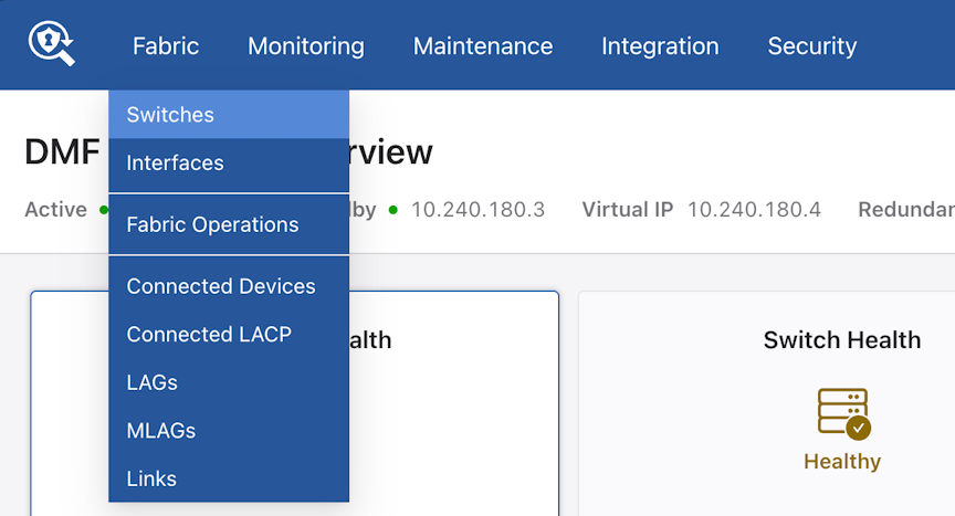 The Switches page lists the switches connected to the DANZ Monitoring Fabric (DMF) Controller, and the IP Address Allocation tab provides controls for configuring a pool of IPv4 addresses for IPAM assignment to the fabric switches.
Figure 2. Switches 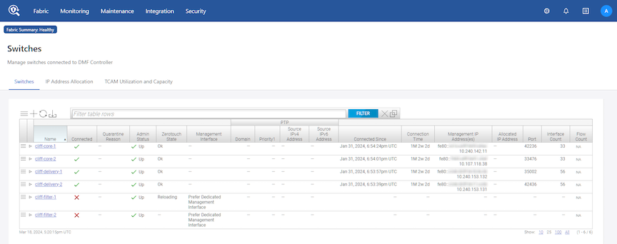
- Click the Edit Configuration control at the top of the IP Address Allocation tab.
Figure 3. IP Address Allocation Tab 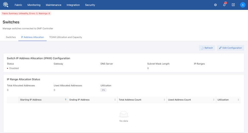
- In the Edit Switch IP Address Allocation dialog, enable IPAM using the Status switch, and specify the Gateway, DNS Server, and Subnet Mask Length.
Figure 4. Edit Switch IP Address Allocation Dialog 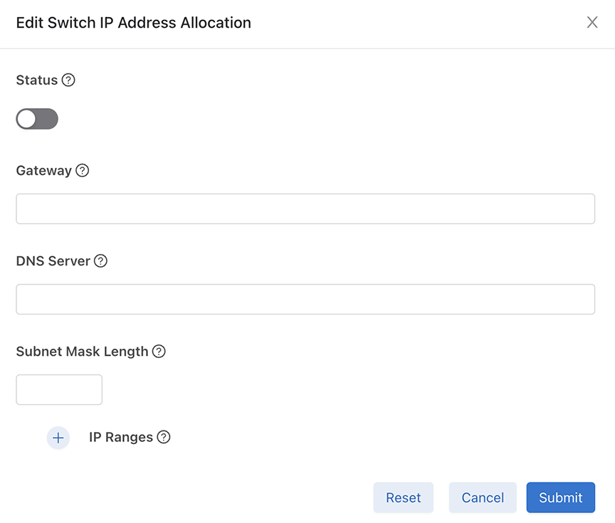
- To view the operational state of IPAM in the fabric and confirm the address range, select from the main menu and click on the IP Address Allocation tab. To view the IP address assignment for each switch, click on the + icon.
Figure 5. Viewing Operational State 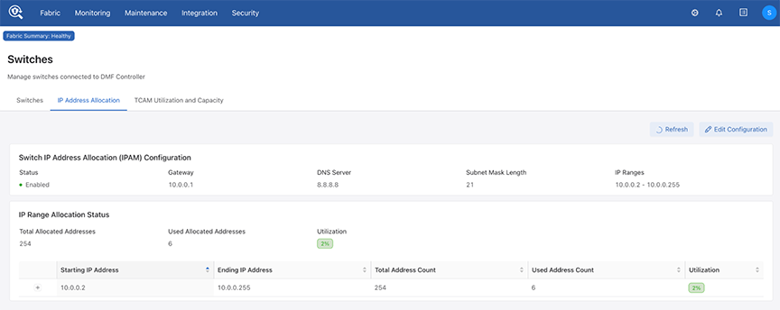
Figure 6. Viewing IP Address Assignments 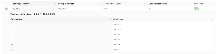
Using the CLI to Allocate IPv4 Addresses with IPAM
Assigning Static IPv4 Addresses
If needed, a static IPv4 address can be assigned to a switch in a fabric managed by IPAM. Removing the assigned address will return the switch to IPAM address management, and an IPv4 address will be assigned to it from the allocated pool if one is available.
Using the GUI to Assign a Static IPv4 Address
- Select from the main menu and select the IP Address Allocation tab.
Figure 7. Accessing the Switches Page - On the Switches tab, click the menu icon next to the switch to which the address will be assigned, and select Configure from the menu.
Figure 8. Switches Figure 9. Configure 
- In the Configure Switch dialog, set the IP Assignment Type to
Manualand enter the desired IPv4 address for the switch.Figure 10. Configure Switch 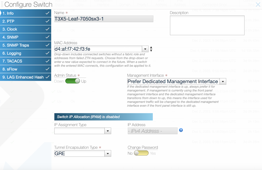 Note: The assigned static address must be in the defined IPAM subnet.
 - To confirm the IP address assignment for the switch, select from the main menu and click on the IP Address Allocation tab, then click on the + icon to display IP addresses for all switches.
Figure 11. Viewing IP Address Assignments
Using the CLI to Assign a Static IPv4 Address
auto as shown below:
controller-1(config)# show running-config switch core1

! switch
switch core1
  ip-address auto 10.0.0.2
  mac 00:53:00:57:c9:3b
Static Address Assignment Troubleshooting and Limitations
Syslog Messages and Tracing
There are no syslog messages associated with this feature. To gain insight into the IPAM IP allocation process, enable tracing logs.
controller-1(config)#logging level org.projectfloodlight.core.ipalloc trace
controller-1(config)#logging level org.projectfloodlight.zerotouch.startupconfig trace
controller-1(config)#show logging controller | grep Ipam
Locate relevant log output in the floodlight syslog at /var/log/floodlight/floodlight.log.
Troubleshooting
When troubleshooting, be sure to use the show ipam switch command to display actual IP address allocations instead of the show running-config ipam switch command, which only displays the configuration and last used auto IP addresses of the switches.
- IPAM is enabled.
- Make sure that the
allocatefield is present in the IPAM configuration. If not, configure the deployment mode as shown below:controller-1(config)#ipam switch controller-1(config-ipam-switch)#allocate
- Make sure that the ZTN deployment mode is set to
auto-discovery. If not, configure the deployment mode as shown below:controller-1(config)deployment-mode auto-discovery
- Make sure that the
- For a configured s IP address, make sure that the address is in the defined IPAM subnet.
- For an
autoIP address, make sure that there are enough IP addresses in the defined IP address ranges for all switches.Note: AnautoIP address in a switch configuration does not necessarily result in an actual IP address assignment and stays there even if the allocated IP address is unavailable, e.g., if IPAM is disabled or the corresponding IP address range is removed. If a configuration change (such as enabling IPAM or adding an IP address range that includes the allocated address), the switch will get this IP address, which was the last automatically allocated IP address, to promote IP stability. - You may cross-check the applied IP address on the running configuration of the switch as shown below:
controller-1#show switch core1 running-config | grep ip-address
swl interface ip-address 10.0.0.3 prefix 21
- An alternative way to cross-check the IP address of the switch is to connect to it and then execute the ifconfig command to view the IP address of the interface:
> connect switch core1
Switch Light OS SWL-OS-DMF-8.5.x(0), 2023-12-01.02:24-4be6844
Linux core1 4.19.296-OpenNetworkLinux #1 SMP Fri Dec 1 02:35:57 UTC 2023 x86_64

SwitchLight ZTN Manual Configuration. Type help or ? to list commands.

(ztn-config) debug bash
*****************************  WARNING  ******************************

        Any/All activities within bash mode are UNSUPPORTED
This is intended ONLY for additional debugging ONLY by Arista TAC.

         Please type "exit" or Ctrl-D to return to the CLI

*****************************  WARNING  ******************************
root@core1:~# ifconfig -a
eth1: flags=4163<UP,BROADCAST,RUNNING,MULTICAST>  mtu 1500
        inet6 2001:0DB8:0:1:5054:ff:fe59:b9b6  prefixlen 64  scopeid 0x20<link>
...
ma1: flags=5187<UP,BROADCAST,RUNNING,MASTER,MULTICAST>  mtu 1500
        inet 10.0.0.2  netmask 255.255.248.0  broadcast 0.0.0.0
...
Limitations
- Note that the show switch command does not display IPv4 addresses. To cross-check the assigned IPv4 number, examine the running config of the switch. (See Troubleshooting section.)
- In order to enable IPAM, ZTN deployment mode must be configured as
auto-discovery. - IPAM can only manage switch IP addresses in a single subnet, but multiple IP address ranges can be defined in that subnet.
Using L3 ZTN (Pre-Configured) Switch Provisioning Mode
deployment-mode pre-configured command is entered on the DMF Controller to enable Layer 3 ZTF.
Installing Arista 7050X and 7260X Series Using L3 ZTF (Preconfigured) Provisioning Mode
Procedure
Installing Arista 7280R Series Using L3 ZTF (Preconfigured) Provisioning Mode
This is a one-time setup needed to load the DMF-compatible EOS image. When set up, the next Controller upgrade will also automatically upgrade the switches.
Perform these steps on the 7280R Series switch to boot from the DMF Controller.
Installing Arista 7800R3 and 7280R3A Series Using L3 ZTF (Preconfigured) Provisioning Mode
A chassis can have one or more line cards. From a Controller's perspective, a chassis-based switch with multiple line cards, each with its own application-specific integrated circuit (ASIC), is treated as a single switch. When connected, a chassis works like any other switch and requires no user intervention for this support to work. The Controller automatically recognizes the chassis, initiates a handshake, and reacts to any chassis events like line card addition and removal.
Show commands display the modules in each chassis slot, whether line cards or supervisors, display line card properties, and what redundancy mode is active.
-
DCS-7804-CH
-
DCS-7808-CH
-
DCS-7812-CH
-
DCS-7816-CH
- DCS-7289-CH
-
The SSO redundancy protocol is not supported.
This is a one-time setup needed to load the DMF-compatible EOS image. When set up, the next Controller upgrade will also automatically upgrade the switches.
Perform these steps on a 7800R3 or a 7280R3A Series switch to boot from the DMF Controller:
Configuring the Switch Static IP and Controller IP in Interactive ZTF Mode
zcsh CLI, complete the following steps:Installing Arista 7050X and 7260X Series using DHCP with bootfile-name option
The Arista ZTP boot script is served to the Arista switch using DHCP’s bootfile-name option (option #67). The Arista switch downloads and executes this Arista ZTP boot script during its ZTP (Zero Touch Provisioning) phase following boot. The Arista ZTP boot script copies the Switch Light OS files from the DMF Controller and configures the appropriate boot settings on the Arista switch.
Procedure
Installing Arista 7280R Series using DHCP with bootfile-name option
Procedure
Registering a Switch After Initial Deployment
To add a switch to the fabric after initial deployment, register the name and MAC address of the switch with the active DANZ Monitoring Fabric (DMF) Controller. The switch downloads a compatible Switch Light OS image and configuration from the Controller and uses the registered switch name to refer to the switch in the CLI output and GUI displays.
Using the GUI to Register a Switch
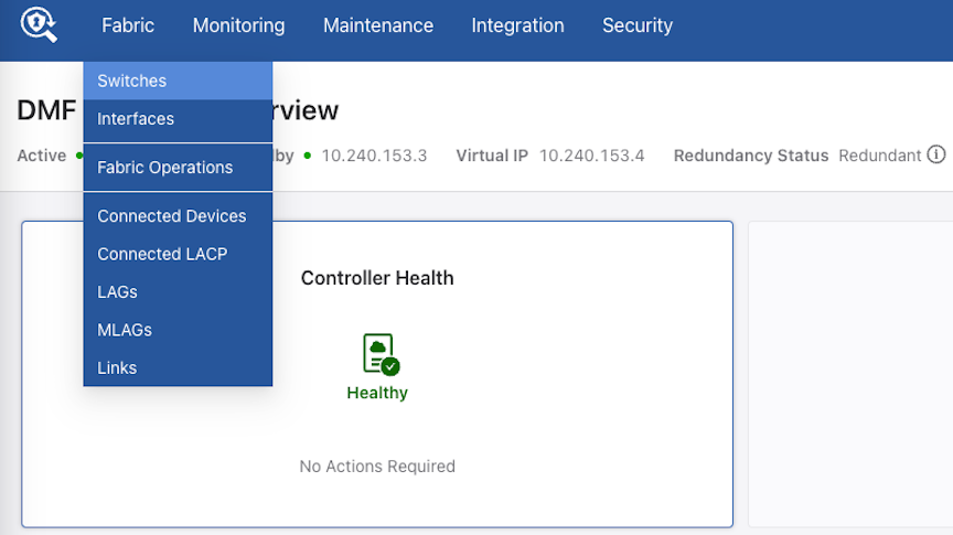
- Select from the main menu.
Figure 12. Fabric Switches Option 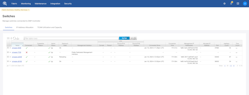
This page lists the switches connected to the DANZ Monitoring Fabric (DMF) Controller, with the current alias of the switch providing a link to the Switch View for the specified switch.
- To add an alias or change the existing alias, click the Menu control next to the switch name and select Configure from the pull-down menu that appears.
Figure 13. Configure Switch (Page 1) 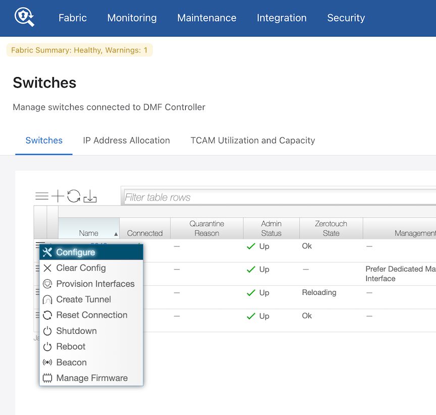
This dialog provides the means to assign a switch name and MAC address, shut down or re-enable the switch, and change the password for direct remote connections to the switch.
Figure 14. Provision Switch Dialog 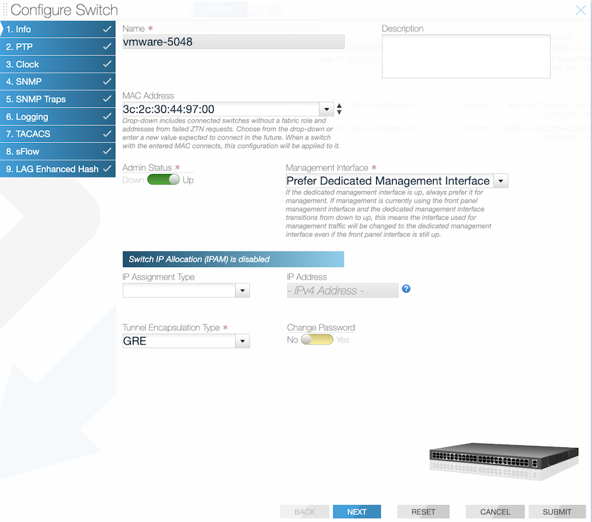
Using the CLI to Register a Switch
switch switch-name command to enter the config-switch submode, to associate the switch name with the MAC address of a physical switch. Replace switch-name with a unique alphanumeric text string. For example, the following commands assign the switch names core-sw-1, filter-sw-1, and delivery-sw-1 to three switches:
controller-1(config)# switch core-sw-1
controller-1(config-switch)# mac d4:af:f7:f9:ee:38
controller-1(config-switch)# switch filter-sw-1
controller-1(config-switch)# mac d4:af:f7:f9:ee:39
controller-1(config-switch)# switch delivery-sw-1
controller-1(config-switch)# mac d4:af:f7:f9:ee:40
show
switch
command from any mode, as in the following example:
controller-1(config)# show switch
# Switch Name   IP Address    State     Pipeline Mode
-|-------------|-------------|---------|---------------------|
1 core-sw-1     172.24.208.91 connected l3-l4-match-push-vlan
2 delivery-sw-1 172.24.208.92 connected l3-l4-match-push-vlan
3 filter-sw-1   172.24.208.93 connected l3-l4-match-push-vlan
The output shows the switch alias, IP address, state, and pipeline mode.
To view additional details about a switch, enter the show switch all detail command, as in the following example:
controller-1(config)# show switch all detail
# Switch Name   Switch MAC Address         Switch DPID             State         IP Address    TCP Port Connected Since                Pipeline Mode
-|-------------|--------------------------|-----------------------|---------|...|-------------|--------|------------------------------|---------------------|
1 core-sw-1     d4:af:f7:f9:ee:38 (Arista) 00:00:d4:af:f7:f9:ee:38 connected     172.24.208.91 37996    2025-03-21 16:04:32.837000 UTC l3-l4-match-push-vlan
2 delivery-sw-1 d4:af:f7:f9:ee:40 (Arista) 00:00:d4:af:f7:f9:ee:40 connected     172.24.208.92 43840    2025-03-21 16:04:31.937000 UTC l3-l4-match-push-vlan
3 filter-sw-1   d4:af:f7:f9:ee:39 (Arista) 00:00:d4:af:f7:f9:ee:39 connected     172.24.208.93 49049    2025-03-21 16:04:31.827000 UTC l3-l4-match-push-vlan
no switch command.
controller-1(config)# no switch DMF-CORE-SWITCH-1
After removing the switch registration, perform a new switch registration using the new switch name.
Changing the ZTF Mode After Deployment
Changing to Layer 3 (Pre-Configured) Switch Provisioning Mode
ZTF cannot be used to install the switches when the switch management network connects the DANZ Monitoring Fabric (DMF) Controllers through a Layer 3 network. However, when a switch is in a different subnet than the Controller, manually configure the switches or use a DHCP server to download the Switch Light OS image to each fabric switch. To do this, change the switch provisioning mode to Pre-Configured.
If the switches and Controllers are in the same L2 broadcast domain, use the auto-discovery switch deployment mode for an L2-ZTF deployment. If the switches and Controllers are not in the same L2 broadcast domain, use the pre-configured provisioning mode to enable an L3-ZTF deployment. The entire fabric must be in a single provisioning mode; DMF only supports the auto-discovery provisioning mode if all the switches are in the same Layer 2 domain.
Using the GUI to Change the Switch Provisioning Mode
Procedure
- Click the Settings control in the Features section on the Controller landing page.
Figure 15. Changing the Switch Provisioning Mode 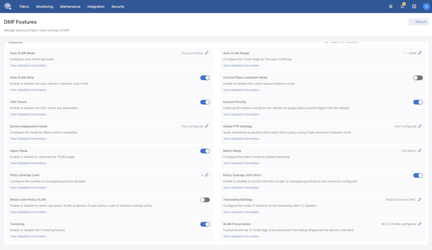 Note: For information about the other options in this section, refer to the DMF User Guide.
 - Click the Settings controller to the right of the Device Provisioning Mode option and click Submit.
Control the configuration of this feature using the Edit icon by clicking on the pencil icon.
Figure 16. Edit Device Deployment Mode 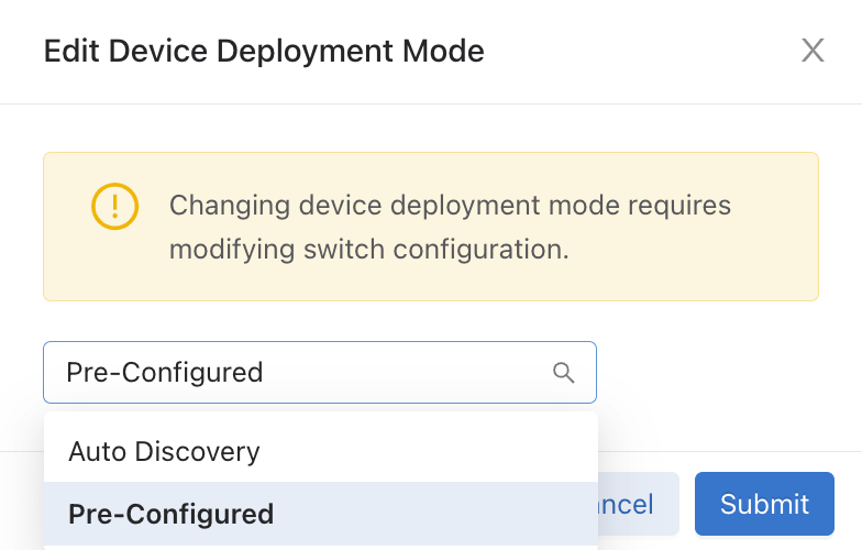
Using the CLI to Change the Switch Provisioning Mode
Procedure
Changing to Layer 3 ZTF (Preconfigured) Mode
Procedure
Changing to Layer 2 ZTF (Auto-Discovery) Mode
Procedure
System Reinstall for an EOS Switch
Perform a system reinstall by removing the local startup-config/zerotouch-config on the switch so the DANZ Monitoring Fabric (DMF) Controller no longer manages it.
Rebooting the switch restarts the Arista-native ZTP process and requests a fresh image from the Controller.
Use the following command to perform a system reinstall:
C1# system reinstall switch eos-switch-name reboot
The following is an example where the switch name is core1.
C1(config)# system reinstall switch core1 reboot
system switch reinstall: "deployment-mode pre-configured"
system switch reinstall: l3-ztn currently configured
system switch reinstall: l3-ztn implies switches are remote
system switch reinstall: l3-ztn and some switches may not rejoin
reinstall may cause service interruption
system switch reinstall ("y" or "yes" to continue): y
An optional parameter called reboot forces the switch to reboot and begin the re-installation process.
CLI Show Commands
When the switch is rebooting, ZTN cannot communicate with the switch, so a Zerotouch state error hint and Zerotouch
state error msg appear when using the following show command:
(config)# show switch core1 zerotouch
Name : core1
Ip address : 10.243.254.25
Last update : 2023-06-02 07:18:35.749000 UTC
Zerotouch state: reloading
Zerotouch state error hint : Rest API Client problem
Zerotouch state error msg : Connect to 10.243.254.25:80 [/10.243.254.25] failed: Connection refused (Connection refused)
The error message changes after the switch has fully booted.
SM-InspiringPare-Broadwater-C1(config-crypto)# show switch core1 zerotouch
Name           : core1
Ip address     : 10.243.254.25
Last update    : 2023-06-02 07:29:34.850000 UTC
Zerotouch state: reloading
Zerotouch state error hint : Rest API Client problem
Zerotouch state error msg  : No route to host (Host unreachable)
At this point, the switch has booted up entirely. Still, the Controller cannot talk to the switch, as the necessary configuration is absent. Kick-start the DMF ZTN process on the switch again using the commands below:
(config)# management dmf
(config-mgmt-dmf)# controller address ip-address
(config-mgmt-dmf)# no disabled
Troubleshooting
Check the status using the command show switch switch-name
zerotouch.
After performing the steps above for reconnecting an EOS switch, and if the state remains stuck in reloading (and there is a Zerotouch state error hint / Zerotouch state error msg output), please contact This email address is being protected from spambots. You need JavaScript enabled to view it..
SKU Reporting for EOS Switches
Like SwitchLight (SWL) OS switches, EOS switches now report their SKUs to the DANZ Monitoring Fabric (DMF) Controller.
View the EOS switch SKU using the DMF Controller CLI or GUI.
Using the CLI to Configure SKU Reporting for EOS Switches
Run the show fabric inventory command from the login mode to view the switch SKUs from the DMF Controller CLI.
SKU column indicates the SKU of each switch.
CONTROLLER-1> show fabric inventory
~~~~~~~~~~~~~~~~~ Controller Inventory ~~~~~~~~~~~~~~~~~
# Node Id Hostname             SKU        Serial Number
-|-------|-------------------|-----------|-------------|
1 29617   CONTROLLER-1        DCA-DM-C450  FF99R52
2 23262   CONTROLLER-2        DCA-DM-C450  3W9D3Y2

~~~~~~~~~~~~~~~~~~~~~~~~~~~~~~~~~ Switch Inventory ~~~~~~~~~~~~~~~~~~~~~~~~~~~~~~~~~
# Switch               SKU               Serial Number Manufacturer    Asic
-|--------------------|-----------------|-------------|---------------|------------|
1 dmf-arista-7280SR2-2 DCS-7280SR2-48YC6 JPE22123192   Arista Networks jericho-plus
2 dmf-arista-7280CR3-1 DCS-7280CR3-32P4  JPE20383391   Arista Networks jericho2
3 dmf-arista-7280SR3-1 DCS-7280SR3-48YC8 JPE22191168   Arista Networks jericho2c
4 dmf-arista-7280CR3-2 DCS-7280CR3-32P4  JPE20383398   Arista Networks jericho2
5 dmf-arista-7280SR-1  DCS-7280SR-48C6   SGD20370893   Arista Networks jericho
6 dmf-arista-7280SR2-1 DCS-7280SR2-48YC6 JPE20476226   Arista Networks jericho-plus

~~~~~~~~~ Recorder Node Inventory  ~~~~~~~~~
# Recorder Node    SKU        Serial Number
-|-----------------|----------|-------------|
1 DMF-RECORDER-NODE DCA-DM-RA3 FLC1RN3

~~~~~~~~ Service Node Inventory  ~~~~~~~~
# Service Node  SKU        Serial Number
-|-----------------|----------|-------------|
1 DMF-SERVICE-NODE  DCA-DM-SDL GS11RN3
Using the GUI to Configure SKU Reporting for EOS Switches
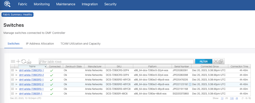
To view the switch SKUs from the DMF Controller GUI, hover the mouse over the Fabric menu bar and select Switches.
The Switches page loads.
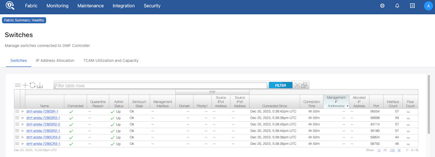
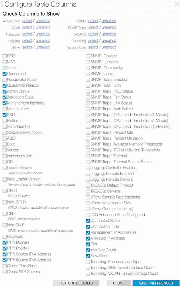
The SKUs do not appear by default but display after enabling the SKU column. To enable the column, click the menu button in the table. In the menu, select Show/Hide Columns.
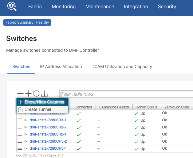
In the dialog box, select the SKU checkbox and click Save Preferences.
The SKU column appears in the Switches table and displays the SKU of each switch.