Management and Control Plane Security

This chapter describes options for increasing the security of management access to the DMF Controller node.


Management Plane Security

The management plane network is used by the administrator, whether locally or remotely, to reach the Controller management interfaces. DANZ Monitoring Fabric (DMF) uses standard, well-known cryptographic technology, such as RSA and AES. Still, system administrators must choose strong passwords and change them frequently, according to well-established security best practices.

All services the Controller uses are enabled by default except for SNMP, which is disabled by default. Refer to the Protocol Access Required to the DMF Controller section to block or permit specific protocols to the management interface.

For example, the control plane is the network between the Controllers and the switches to carry OpenFlow control traffic. The following are general requirements and recommendations for deployment:

  • The Controller must be on the same Layer 2 network as the switches—physically isolated data, control, and management plane networks.
  • The only devices on the control plane are switches and Controllers.
  • Make the control plane network not routed or minimally IP access restricted via its egress router.
  • Physically secure the management and data plane networks (for example, locks on the cage doors).

Many of the Zero-Touch Networking (ZTF) protocols (DHCP, Controller discovery, and image download) and the OpenFlow protocol are not authenticated. They are subject to spoofing in an untrusted network. The following are best practices regarding securing the control plane within the switched fabric.

  • The control plane network is “Layer 2 trusted,” meaning the attacker cannot spoof Layer 2 messages on the control network. In practice, this means the control plane network should be an isolated VLAN, ideally containing only the Controller and switches.
  • Harden the switch management interface against Layer 3 attacks (all services are authenticated, unnecessary services are turned off, and so forth).
  • The network should not be reachable by Layer 3 protocols. If Layer 3 access is required, the administrator should maintain a Layer 3 allowlist of hosts that can access the control network, for example, using an ACL on the edge router.

NTP Server Authentication

Network Time Protocol (NTP) standard authentication enforces cryptographic validation between NTP clients and servers to prevent unauthorized time modification and mitigate man-in-the-middle (MitM) spoofing attacks. Operating primarily via symmetric key cryptography, both the client and server share a pre-configured, secret key identified by a unique 32-bit Key ID. When generating an NTP packet, the sender appends an Authenticator field containing the Key ID and a Message Authentication Code (MAC). This MAC is computed over the entire NTP packet header (excluding the Authenticator field itself) using a keyed-hash algorithm. Upon receipt, the destination independently calculates the MAC using the corresponding local key matched by the Key ID; the packet is discarded if the calculated MAC fails to match the transmitted payload.

Historically, standard NTP authentication relied strictly on the MD5 hashing algorithm to generate the 128-bit MAC payload. While MD5 provides low computational overhead, it has long been cryptographically broken and vulnerable to collision attacks, making it unsuitable for high-security environments.

To address the cryptographic vulnerabilities of MD5, modern NTP implementations introduced native support for the SHA-1 and SHA-256 secure hash algorithms. By leveraging the SHA-2 family, specifically SHA-256, the protocol increases the digest length to 256 bits, substantially enhancing resistance to brute-force and collision vectors.

The DANZ Monitoring Fabric (DMF) management plane uses a standard NTP implementation, introducing support for the more secure SHA-256 hash algorithm in release 8.10 in addition to the legacy SHA-1 option.

By adding the SHA-2 family, specifically SHA-256, the NTP protocol can concurrently support legacy connections alongside hardened SHA-256 connections, facilitating a phased migration toward stronger cryptographic standards without disrupting network-wide synchronization.

Configuration

The SHA-256 hash algorithm configuration requires the administrator to specify the sha256 keyword as part of the NTP key configuration (sha1 is also an option for legacy algorithm support):

dmf-controller(config)# ntp key 65 sha256 7 025650585f5f09784f1a5d4c071244095f012b79262a306223105f4e025502005a0600585440140d0e040704070c5d08075500545d440006585c540e774d1e501d
dmf-controller(config)# ntp server 10.240.189.181 key 65

You can verify the configuration on the controller like so:

dmf-controller(config)# show run ntp
! ntp
ntp key 65 sha256 7 025650585f5f09784f1a5d4c071244095f012b79262a306223105f4e025502005a0600585440140d0e040704070c5d08075500545d440006585c540e774d1e501d
ntp server 10.240.189.181 key 65

To verify the correct synchronization, check that the show ntp status output displays synchronized:

dmf-controller(config)# show ntp status
Status : synchronized

Upon successful authentication, the auth status column should show ok.

dmf-controller(config)# show ntp auth 
ind assid status  conf reach auth condition  last_event cnt
===========================================================
  1 17767  f61a   yes   yes   ok   sys.peer    sys_peer  1

Check whether the server’s authentication is showing as bad, which might indicate that there’s a mismatch between the key set for the server on the Controller or managed device and the NTP server itself:

dmf-controller(config)# show ntp auth
ind assid status  conf reach auth condition  last_event cnt
===========================================================
  1 17767  c011   yes    no   bad    reject    mobilize  1


Moreover, the ntp-key REST API also adds support for the SHA256 hash option in the key-type field:

POST /api/v1/data/controller/os/config/global/time/ntp-key

{
  "key-id": 65,
  "key-type": "sha256",
  "key-value": "025650585f5f09784f1a5d4c071244095f012b79262a306223105f4e025502005a0600585440140d0e040704070c5d08075500545d440006585c540e774d1e501d"
}

POST /api/v1/data/controller/os/config/global/time/ntp-server
{
  "server": "10.240.189.181",
  "key-id": 65
}

Importing the Controller Private Key and Certificate

This section describes how to import a private key and a certificate to the Controller after copying it to the Controller using the copy command.

Note: DMF does not support the use of encrypted private keys, so decrypt an encrypted private key before importing/copying it to DMF, as shown in the following example:
root@Ubuntu-12:~/openssl-ca/admin/pkcs1# openssl rsa -in ../pkcsl.key -out decrypt-pcsl.key
Enter pass phrase for ../pkcsl.key: ********
writing RSA key
root@Ubuntu-12:~/openssl-ca/admin/pkcs1#
To import a private key to the Controller, enter the private-key command in the config-controller submode:
[no] private-key <controller-key-name>

Replace controller-key-name with the name of the private key. Use the no version of the command to remove the private-key.

To import the Controller certificate, use the certificate command in config-controller submode.
[no] certificate <name>

Replace the name with the name assigned to the Controller certificate. Use the no version of the command to remove the certificate.

Import the private key and certificate to the Controller using the copy command.

Using Certificates Signed by a CA for GUI Access to the Controller

By default, SSL is enabled on the Controller using a self-signed certificate. Complete the following steps to install a certificate signed by a public or private CA.

Procedure

  1. Generate the Certificate Signing Request (CSR) and the private key for the Controller.
    Perform this operation on any workstation that supports OpenSSL. The following example shows the operation performed on a Linux workstation.
    root@Ubuntu-12:~/openssl-ca/admin#openssl req -newkey rsa:2048 -nodes -keyout controller.
    key -new -out controller.csr
    Generating a 2048 bit RSA private key
    .......................................+++
    ...............................+++
    writing new private key to 'controller.key'
    -----
    You are about to be asked to enter information that will be incorporated into your
    certificate request.
    What you are about to enter is what is called a Distinguished Name or a DN. There are
    quite a few fields but you can leave some blank
    For some fields there will be a default value,
    If you enter '.', the field will be left blank.
    -----
    Country Name (2 letter code) [AU]:US
    State or Province Name (full name) [Some-State]:California
    Locality Name (eg, city) []:Santa Clara
    Organization Name (eg, company) [Internet Widgits Pty Ltd]:Arista Networks Organizational
    Unit Name (eg, section) []:Engineering
    Common Name (e.g. server FQDN or YOUR name) []:DMF Secure Certificate
    Email Address []:This email address is being protected from spambots. You need JavaScript enabled to view it.
    Please enter the following 'extra' attributes
    to be sent with your certificate request
    A challenge password []:anet1234
    An optional company name []:Arista
    root@Ubuntu-12:~/openssl-ca/admin#
    root@Ubuntu-12:~/openssl-ca/admin# ls -ltr
    total 8
    -rw-r--r-- 1 root root 1708 Feb 7 15:39 controller.key
    -rw-r--r-- 1 root root 1184 Feb 7 15:39 controller.csr
    root@Ubuntu-12:~/openssl-ca/admin#
    Important: A Subject Alternate Name (SAN) is required to access the DMF controller using the IP addresses of the active/standby controllers or any FQDN names other than the Common Name (CN). The SAN needs to be defined as part of the CSR generation process.


    The following is an example of CSR generation with SAN using the openssl command.

    You can generate a new private key and a CSR, explicitly defining the SAN in the command parameters. First, generate a private key:

    openssl genrsa -out controller.key 2048
    Then generate a CSR for a specified subjectAltName (SAN):
    openssl req -new -key controller.key -out controller.csr -addext "subjectAltName = DNS:example.com,DNS:www.example.com,DNS:sub.example.com"
    
    Alternatively, you can create a req.conf file to include the SAN definition. For example:
    [req]
    distinguished_name = req_distinguished_name
    req_extensions = v3_req
    prompt = no
    [req_distinguished_name]
    C = US
    ST = State
    L = City
    O = Organization
    CN = example.com
    [v3_req]
    keyUsage = keyEncipherment, dataEncipherment
    extendedKeyUsage = serverAuth
    subjectAltName = @alt_names
    [alt_names]
    DNS.1 = example.com
    DNS.2 = www.example.com
    IP.1 = 192.168.1.1 <active controller IP>
    IP.2 = 203.0.113.100 <standby controller IP>
    
    
    Then run:
    openssl req -new -out controller.csr -key controller.key -config req.conf. 
    
  2. Submit the CSR to the CA and get the certificate signed.

    Submit the CSR to the trusted CA for browsers used to access the DMF GUI. For organizations using GUI-based CAs, copy the contents of the CSR to the CA for signature.

    The following example shows the operation performed on a Linux workstation.
    root@Ubuntu-12:~/openssl-ca# openssl ca -config openssl-ca.cnf -policy signing_policy -
    extensions signing_req -out admin/controller.pem -infiles admin/controller.csr
    Using configuration from openssl-ca.cnf
    Check that the request matches the signature
    Signature ok
    The Subject's Distinguished Name is as follows
    countryName :Printable:'US'
    stateOrProvinceName :ASN.1 12:'California'
    localityName :ASN.1 12:'Santa Clara'
    organizationName :ASN.1 12:'Arista Networks'
    organizationalUnitName:ASN.1 12:'Engineering'
    commonName :ASN.1 12:'DMF Secure Certificate'
    Certificate is to be certified until Nov 3 23:41:17 2020 GMT (1000 days) Sign the
    certificate? [y/n]:y
    1 out of 1 certificate requests certified, commit? [y/n]y Write out database with 1 new
    entries
    Data Base Updated
    root@Ubuntu-12:~/openssl-ca#
    root@Ubuntu-12:~/openssl-ca/admin# ls -ltr
    total 16
    -rw-r--r-- 1 root root 1708 Feb 7 15:39 controller.key
    -rw-r--r-- 1 root root 1184 Feb 7 15:39 controller.csr
    -rw-r--r-- 1 root root 5882 Feb 7 15:41 controller.pem
    root@Ubuntu-12:~/openssl-ca/admin#
  3. Copy the signed certificate to the Controller:
    controller-1# copy scp://This email address is being protected from spambots. You need JavaScript enabled to view it..3:/root/openssl-ca/admin/controller.pem cert://
    This email address is being protected from spambots. You need JavaScript enabled to view it..3's password:
    controller.pem
    5.74KB - 00:00
    controller-1# copy scp://This email address is being protected from spambots. You need JavaScript enabled to view it..3:/root/openssl-ca/admin/controller.key private-key:/
    /controller- private.key
    This email address is being protected from spambots. You need JavaScript enabled to view it..3's password:
    controller.key
    1.67KB - 00:00
    controller-1#
  4. Verify that the certificate was copied correctly:
    controller-1# show secure
    <SNIP>
    ~~~~~~~~~ Cert ~~~~~~~~~
    # Name
    -|----------------------|
    1 DMF Secure Certificate 2 QA CA
    3 ovsclient
    ~~~~~~~~~~~ Csr ~~~~~~~~~~~
    #  Name
    - |------------------------ |
    1  12358.controller.cluster
    2  32591.controller.cluster
    ~~~~~~~~~~~~~~~~~~~~~~~~~~~~~~~~~~~ Private Keys~~~~~~~~~~~~~~~~~~~~~~~~~~~~~~~~~~~~~~~~~~~~~
    Name                    Algorithm  Value 
    ---------------------- |--------- |-----------------------------------------------------------------------------------------------|
    controller-private.key  sha256     DB:6D:C1:01:E2:CD:71:C4:AA:54:FA:6F:3F:80:4E:C7:25:4C:A9:2A:CA:7F:F5:44:CF:37:3C:C7:67:93:19:BB
    ovsclient               sha256     EB:88:0C:9D:EE:37:AA:BA:1A:6E:7B:F9:6E:7F:89:45:69:C4:7F:58:D3:18:D2:DC:49:16:2E:1D:2A:2B:94:89
    controller-1#
  5. Apply the certificate and private key.
    controller-1(config-controller)# certificate DMF\Secure\Certificate
    controller-1(config-controller)# private-key controller-private.key
  6. Display the Controller security configuration.
    controller-1(config-controller)# show this
    ! controller
    controller
    certificate 'DMF Secure Certificate'
    cluster-name DMF_Cluster
    private-key controller-private.key
    access-control
    !
    access-list api
    1 permit from ::/0
    2 permit from 0.0.0.0/0
    !
    access-list gui
    1 permit from ::/0
    2 permit from 0.0.0.0/0
    !
    access-list ssh
    1 permit from ::/0
    2 permit from 0.0.0.0/0
    controller-1(config-controller)#
  7. Access the DMF GUI using a browser and display the certificate.
     
  8. After connecting to the Controller, click the padlock icon to the left of the location field to display information about the certificate.

Replacing the Certificate

Please use the following steps to replace the Controller's certificate.

Scenario 1: Using the same CSR used to sign the current certificate.

Obtain a newly signed certificate from CA using the same CSR and copy it to the Controller using the following command:

# copy new certificate from the source cert://
For example:
# copy scp://This email address is being protected from spambots. You need JavaScript enabled to view it./root/openssl-ca/certificate.pem cert:// This email address is being protected from spambots. You need JavaScript enabled to view it. password certificate.pem 
6.49KB - 00:00 
# 
No other action is needed as the current certificate will be overwritten when copying the new one.

Scenario 2: Does not have the same CSR for the current certificate.

  1. Generate a new CSR and the private key.
  2. Sign the CSR to get the new certificate.
  3. Import/copy the certificate to the Controller. The current certificate will be overwritten if the Common Name matches the new one.
  4. Import/copy the new private key to the Controller. The private key will be overwritten if the file name is the same as the old one. In that case, there is no need for any config changes.
Assuming the Common Name and the private key dest file names are different from the original ones, remove the old certificate and private key and install a new certificate and private key.
To remove the old certificate and private key, use the following commands:
C1(config)# controller
C1(config-controller)# no certificate certificate name
C1(config-controller)# no private-key private-key name
C1(config-controller)#
To configure the new certificate and private key, use the following commands:
C1(config)# controller
C1(config-controller)# certificate new certificate name
C1(config-controller)# private-key new private-key name
C1(config-controller)#

Manage Certificates and Private Keys in the DMF UI

Please use the following steps to manage certificates and private keys in DMF.

Overview


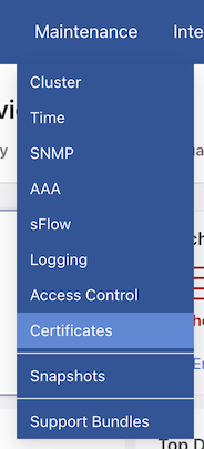
Navigate to MaintenanceCertificates and select Certificates.

Figure 1. Maintenance > Certificates
Figure 2. DMF UI Certificate


Certificates

DMF displays a list of available certificates and features to manage the certificates, including search, certificate import, deletion, data export, and filtering by column.

Figure 3. List of Available Certificates

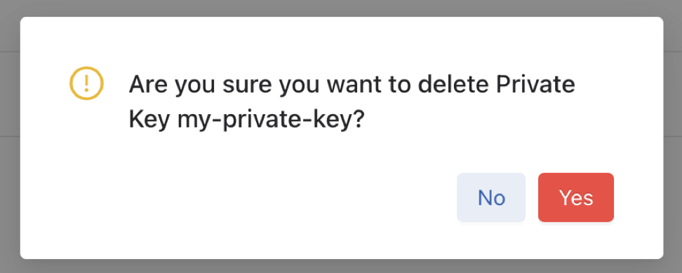
To delete individual certificates, select Delete on the row action menu, followed by Yes.

Figure 4. How to Delete Certificates
Figure 5. Confirmation Window


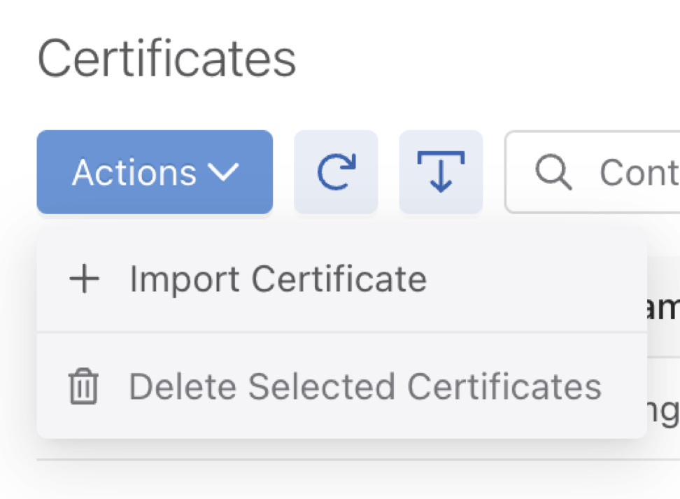
Table Actions:

Figure 6. Certificates > Import Certificate
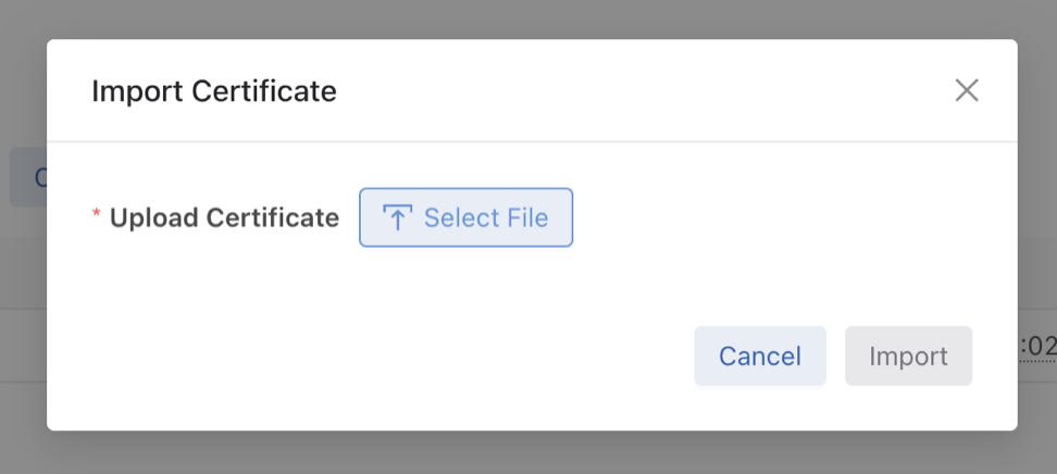
  • Import Certificate: To import a certificate, use Select File, choose the file, and click Import.

Figure 7. Import Certificate Window
  • Delete Selected Certificates: Select a table row checkbox to delete the specific certificates, followed by Yes to confirm the deletion.
Figure 8. Confirmation Window

Private Keys

DMF displays a list of available private keys and features to manage the private keys, including search, private key import, deletion, data export, and filtering by column.

Figure 9. List of Private Keys

To delete private keys, select Delete on the row action menu, followed by Yes.
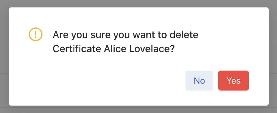
Figure 10. How to Delete Private Keys
Figure 11. Confirmation Window


Table Actions:

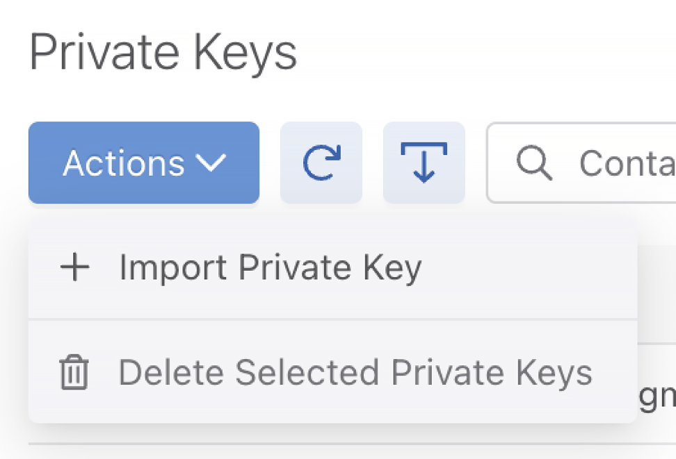
Figure 12. Private Keys > Import Private Key
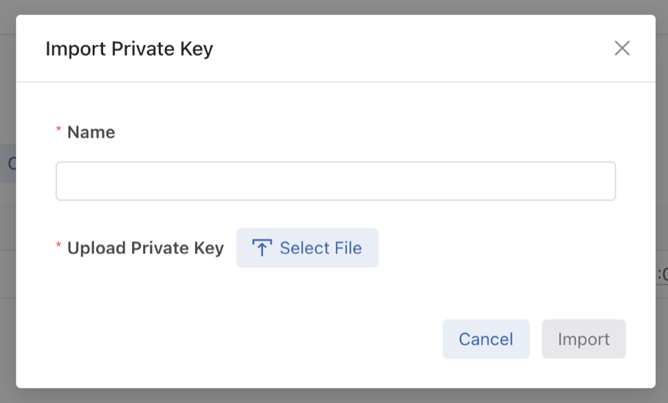
  • Import Private Key: To import a private key, use Select File, choose the file, enter the name, and click Import.

    Figure 13. Import Private Key Window


  • Delete Selected Private Keys: Select a table row checkbox to delete the specific private keys, followed by Yes to confirm the deletion.


    Figure 14. Confirmation Window


DMF UI Certificate

Figure 15. DMF UI Certificate

To configure DMF UI certificates, use the Edit button. Choose the Certificate Name and Private key Name, followed by Submit.
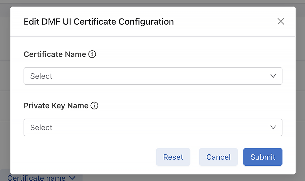
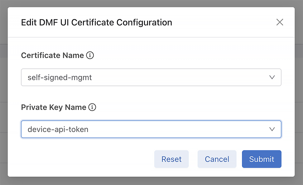
Figure 16. Edit DMF UI Certificate Configuration
Figure 17. DMF UI Certificate Selection


Figure 18. Selected DMF UI Certificate

Generate Public/Private Keys and CSRs on DMF Appliances

Starting from DMF release 8.9.0, this feature enables the direct generation of public/private key pairs and TLS Certificate Signing Requests (CSRs) on DMF appliances. With prior releases the workflow required generating keys and CSRs externally, followed by importing the private key and CA-signed certificate. This enhancement simplifies the process by securely retaining the private key on the appliance, eliminating the need for external key management.


Procedure

Install a new TLS certificate by following these steps:
  1. Generate Key Pair
    Create a new private/public key pair on the appliance. The supported encryption algorithms include:
    • RSA: 2048, 3072, or 4096-bit modulus
    • Elliptic-Curve DSA (ECDSA): P-256, P-384, or P-521 curve.
  2. Create Certificate Signing Request (CSR)
    Using the generated public key, create a CSR containing the required information for the Certificate Authority (CA).
  3. Obtain Signed Certificate
    Submit the CSR to the CA to obtain a signed certificate.
  4. Import Certificate
    Import the signed certificate onto the appliance.
     
Usage: The certificates secure GUI access and REST API queries.

Securing DMF Appliance Communications Using Custom Certificates

Configuration Summary

To secure appliance communications using custom certificates, follow this general workflow:

  1. Generate Key Pair: Create a unique public/private key pair on the appliance.

  2. Create CSR: Generate a Certificate Signing Request (CSR) linked to the generated public key.

  3. Sign Certificate: Export the CSR content and submit it to the Certificate Authority (CA) for signing.

  4. Import Certificate: Upload the signed certificate returned by the CA to the appliance.

  5. Apply Configuration: Update specific system services (such as the Controller UI, Syslog, or RADIUS) to use the new certificate by referencing its SHA256 fingerprint.

CLI Configuration

Create Public/Private Key Pairs

Generate key pairs using the create key-pair command.

# create key-pair mykeyname rsa3072
Fingerprint           : 37:4E:2F:82:08:45:88:C6:2D:6B:43:FD:73:EC:9A:08:CF:8C:41:E2:62:1A:DB:3E:19:34:CB:18:7C:5B:07:F7
Fingerprint algorithm : sha256
Name                  : test-key


Parameters
  • Nickname (Required): A unique name associated with the key pair (e.g., mykeyname). Duplicate nicknames trigger an error.

  • Algorithm (Optional): Specifies the encryption algorithm and key size. If omitted, the default is rsa2048.

  • RSA: rsa2048, rsa3072, rsa4096

  • Elliptic-Curve DSA: ecdsa256 (P-256), ecdsa384 (P-384), ecdsa521 (P-521)


Example Output


Output Details
  • Fingerprint: The SHA256 hash of the newly created public key.

  • Fingerprint algorithm: Always displays sha256.

  • Name: The unique nickname assigned to the key pair.


Note: The system reserves the names self-signed-mgmt and device-api-token. Do not use these names for new key pairs.

Show Public Keys

Display all public keys present on the appliance using the show public-key command.

# show public-key 
# Name             Algorithm Fingerprint                                                                                     
-|----------------|---------|-----------------------------------------------------------------------------------------------|
1 self-signed-mgmt sha256    7A:9C:F3:BE:79:BB:A2:C1:9F:03:4C:BD:93:EA:12:9B:5A:6A:82:85:24:26:25:B7:F0:5F:B3:F6:B9:A5:90:48
2 test-key         sha256    69:92:63:DA:C7:F9:B4:91:BD:92:3F:D3:87:14:4E:B0:88:DB:42:42:DF:0A:D5:33:3C:32:95:32:A7:78:E3:B0

# show public-key 7A:9C:F3:BE:79:BB:A2:C1:9F:03:4C:BD:93:EA:12:9B:5A:6A:82:85:24:26:25:B7:F0:5F:B3:F6:B9:A5:90:48 
Name        : self-signed-mgmt
Algorithm   : sha256
Fingerprint : 7A:9C:F3:BE:79:BB:A2:C1:9F:03:4C:BD:93:EA:12:9B:5A:6A:82:85:24:26:25:B7:F0:5F:B3:F6:B9:A5:90:48

Delete Private/Public Key Pair

Delete a key pair via the CLI using the delete public-key command.

# delete public-key 37:4E:2F:82:08:45:88:C6:2D:6B:43:FD:73:EC:9A:08:CF:8C:41:E2:62:1A:DB:3E:19:34:CB:18:7C:5B:07:F7

Procedure

  1. Retrieve Fingerprint: Identify the target key's SHA256 fingerprint using the show public-key command.

  2. Execute Deletion: Run the delete public-key command with the specific fingerprint.

Warning: Do not delete the self-signed-mgmt or device-api-token key pairs. Deleting these reserved keys results in undefined system behavior.

Create Certificate Signing Request

Generate the Certificate Signing Request (CSR) using the create csr command.

# create csr mycn.com 37:4E:2F:82:08:45:88:C6:2D:6B:43:FD:73:EC:9A:08:CF:8C:41:E2:62:1A:DB:3E:19:34:CB:18:7C:“Arista Inc.” “Customer Service” “Santa Clara” California US san-ip “1.1.1.1,2.2.2.2” san-dns “cs.mycn.com,en.mycn.com” certificate-purpose webserver digest sha256
Content : -----BEGIN CERTIFICATE REQUEST-----
MIIEMDCCApgCAQAwfDERMA8GA1UEAwwIbXljbi5jb20xFDASBgNVBAoMC0FyaXN0
YSBJbmMuMRkwFwYDVQQLDBBDdXN0b21lciBTZXJ2aWNlMRQwEgYDVQQHDAtTYW50
YSBDbGFyYTETMBEGA1UECAwKQ2FsaWZvcm5pYTELMAkGA1UEBhMCVVMwggGiMA0G
CSqGSIb3DQEBAQUAA4IBjwAwggGKAoIBgQDzBygBEa30Zq0PywZmi+IQcNJ4I8IP
tJVMQxK0ynjqTWrDcjolIA9GuoFHEtIfA2+ja3xvoFRXIFMyVUuITLkwhhZeEOUP
kyD61WPNX+DUg4ANpYW/nu2LGjQtbz24iS6In3Udi2Nvh1pn+8uM3p//GsMy7kK0
jwRHKmB9UynXFoaVkMF6XjxAJ4/n4+ck2inP29BW+q1hPlpjiXwLVmVPTpDNvAXE
H/+3zk4t8PTUlMD7xoFHghx7moV3R5A6cIT21wFae9VjjY78B6PcaP4pzZ5VV05B
aJ89559W2Mzd0HjMEv8OhkNV+xFBy6eyh6tT/FgxR7PceNzt7BwkNQ/zCIgqDv+z
NqzymK+T96sXtxrywlyVJWJmNwilqJeYVcRQ7bqItzq59OS4g0m41hi4O6IBIbZG
ngKB9g6RdXjb5oN5XGfnilCCGkq6v3f75nkPhJB4fyVvkNJWy7svNxGEbgIRHXt8
xzrIy/Qy3i8nQMw3aPVarM2UhcYlwWT8e2UCAwEAAaBvMG0GCSqGSIb3DQEJDjFg
MF4wLwYDVR0RBCgwJocEAQEBAYcEAgICAoILY3MubXljbi5jb22CC2VuLm15Y24u
Y29tMAkGA1UdEwQCMAAwCwYDVR0PBAQDAgOoMBMGA1UdJQQMMAoGCCsGAQUFBwMB
MA0GCSqGSIb3DQEBCwUAA4IBgQBUMqrUgKw6pDK4uE8lhjSArdxx5QkRwJdvszWj
WS6Tb+p6qs5yDcp4KJyxcGoyn2tp33C06AhRvAZ+ZQgsz+4wHH06b5FxtDKVBLv5
SWR9GEn8u5ZOhACUNKNh1tAAQOyLyoFKwBvFQ6IaWP8YICeXO3Jg6+uzinpN3DQx
yS8Z1nJ6c2FkjiPYHWmAaWib7iBMEnFvqkrfoFXvZBIwLV4nFYq3ZfcRlL7oQFRg
hNougNuW/KKgJ+S95RJCLnqEgmm5XhIcgXTZU262wF0ctdt3Jzpwbwvf6VnMRjMr
whxt+2wsqqqWYty0MxgTbqpqjy4nSw6eSh36NvsdA9ExCxaj24LEHomfZlRHzLl/
C5HHAeplJ8l79cDlGThnjz1qU+iRfccuqw2JSCiqUo2zMy41y+Fr38jAF7vv4RwU
xC63pe+haiVcx1H6MNgHJgGTe+tjoPvo3wpQyt9W09vXwH9Y0j6/YAWH53qFz7El
rKLrNMjwaarJrE4hv+BUC1UV/ZQ=
-----END CERTIFICATE REQUEST-----
Fingerprint :
69:CB:DD:49:7D:64:FF:DE:EA:C4:C6:E2:C9:03:E6:ED:74:A
3:49:44:88:5E:98:0D:AE:C3:46:77:0F:8B:55:69
Fingerprint algorithm : sha256
Name : mycn.com

Input Parameters

The input requires a JSON object containing the following fields:

  • cn (Common Name): Requires a valid domain name.

  • org (Organization): The legal name of the organization.

  • ou (Organization Unit): The division or department within the organization.

  • city: The city or locality name.

  • state: The state or province name.

  • country: The two-letter ISO country code.

  • san-ip: A list of IPv4 or IPv6 addresses to use as Subject Alternative Names (SANs).

  • san-dns: A list of domain names to use as Subject Alternative Names (SANs).

  • public-key-fingerprint: The fingerprint of the previously created public key.

  • certificate-purpose: Defines the Key Usage and Extended Key Usage for the certificate. The only supported value is web-server.

  • digest: The signature algorithm. Supported values include:

    • sha256

    • sha384

    • sha512

Response Fields

The system returns a response with the following fields:

  • fingerprint-algorithm: Always returns sha256.

  • fingerprint: The SHA256 fingerprint of the generated CSR.

  • name: The Common Name (CN) of the CSR.

  • content: The CSR content in PEM format. Copy this content to the Certificate Authority (CA) to request a signed certificate.

Note: The system automatically removes any existing CSR associated with the provided public key from the appliance.

Show Certificate Signing Requests

Display all Certificate Signing Requests (CSRs) present on the appliance using the show csr command.

# show csr 
# Name     Algorithm Fingerprint                                                                                     
-|--------|---------|-----------------------------------------------------------------------------------------------|
1 mycn.com sha256    69:CB:DD:49:7D:64:FF:DE:EA:C4:C6:E2:C9:03:E6:ED:74:A3:49:44:88:5E:98:0D:AE:C3:46:77:0F:8B:55:69

# show csr 69:CB:DD:49:7D:64:FF:DE:EA:C4:C6:E2:C9:03:E6:ED:74:A3:49:44:88:5E:98:0D:AE:C3:46:77:0F:8B:55:69 
Name        : mycn.com
Algorithm   : sha256
Fingerprint : 69:CB:DD:49:7D:64:FF:DE:EA:C4:C6:E2:C9:03:E6:ED:74:A3:49:44:88:5E:98:0D:AE:C3:46:77:0F:8B:55:69
Content     : -----BEGIN CERTIFICATE REQUEST-----
MIIEMDCCApgCAQAwfDERMA8GA1UEAwwIbXljbi5jb20xFDASBgNVBAoMC0FyaXN0
YSBJbmMuMRkwFwYDVQQLDBBDdXN0b21lciBTZXJ2aWNlMRQwEgYDVQQHDAtTYW50
YSBDbGFyYTETMBEGA1UECAwKQ2FsaWZvcm5pYTELMAkGA1UEBhMCVVMwggGiMA0G
CSqGSIb3DQEBAQUAA4IBjwAwggGKAoIBgQDzBygBEa30Zq0PywZmi+IQcNJ4I8IP
tJVMQxK0ynjqTWrDcjolIA9GuoFHEtIfA2+ja3xvoFRXIFMyVUuITLkwhhZeEOUP
kyD61WPNX+DUg4ANpYW/nu2LGjQtbz24iS6In3Udi2Nvh1pn+8uM3p//GsMy7kK0
jwRHKmB9UynXFoaVkMF6XjxAJ4/n4+ck2inP29BW+q1hPlpjiXwLVmVPTpDNvAXE
H/+3zk4t8PTUlMD7xoFHghx7moV3R5A6cIT21wFae9VjjY78B6PcaP4pzZ5VV05B
aJ89559W2Mzd0HjMEv8OhkNV+xFBy6eyh6tT/FgxR7PceNzt7BwkNQ/zCIgqDv+z
NqzymK+T96sXtxrywlyVJWJmNwilqJeYVcRQ7bqItzq59OS4g0m41hi4O6IBIbZG
ngKB9g6RdXjb5oN5XGfnilCCGkq6v3f75nkPhJB4fyVvkNJWy7svNxGEbgIRHXt8
xzrIy/Qy3i8nQMw3aPVarM2UhcYlwWT8e2UCAwEAAaBvMG0GCSqGSIb3DQEJDjFg
MF4wLwYDVR0RBCgwJocEAQEBAYcEAgICAoILY3MubXljbi5jb22CC2VuLm15Y24u
Y29tMAkGA1UdEwQCMAAwCwYDVR0PBAQDAgOoMBMGA1UdJQQMMAoGCCsGAQUFBwMB
MA0GCSqGSIb3DQEBCwUAA4IBgQBUMqrUgKw6pDK4uE8lhjSArdxx5QkRwJdvszWj
WS6Tb+p6qs5yDcp4KJyxcGoyn2tp33C06AhRvAZ+ZQgsz+4wHH06b5FxtDKVBLv5
SWR9GEn8u5ZOhACUNKNh1tAAQOyLyoFKwBvFQ6IaWP8YICeXO3Jg6+uzinpN3DQx
yS8Z1nJ6c2FkjiPYHWmAaWib7iBMEnFvqkrfoFXvZBIwLV4nFYq3ZfcRlL7oQFRg
hNougNuW/KKgJ+S95RJCLnqEgmm5XhIcgXTZU262wF0ctdt3Jzpwbwvf6VnMRjMr
whxt+2wsqqqWYty0MxgTbqpqjy4nSw6eSh36NvsdA9ExCxaj24LEHomfZlRHzLl/
C5HHAeplJ8l79cDlGThnjz1qU+iRfccuqw2JSCiqUo2zMy41y+Fr38jAF7vv4RwU
xC63pe+haiVcx1H6MNgHJgGTe+tjoPvo3wpQyt9W09vXwH9Y0j6/YAWH53qFz7El
rKLrNMjwaarJrE4hv+BUC1UV/ZQ=
-----END CERTIFICATE REQUEST-----

Delete a CSR

Delete a Certificate Signing Request (CSR) via the CLI using the delete csr command.

# delete csr 37:4E:2F:82:08:45:88:C6:2D:6B:43:FD:73:EC:9A:08:CF:8C:41:E2:62:1A:DB:3E:19:34:CB:18:7C:5B:07:F7
Procedure
  1. Retrieve Fingerprint: Identify the target CSR's SHA256 fingerprint using the show csr command.

  2. Execute Deletion: Run the delete csr command with the specific fingerprint.

Import a Signed Certificate

After the Certificate Authority (CA) produces a signed certificate, import it onto the appliance using Secure Copy Protocol (SCP) from an external device.

(external)$ scp ./mycert.pem username@10.0.0.1://cert


Import Behavior and Constraints
  • CSR Cleanup: If the imported certificate matches an existing CSR's Common Name and Public Key, the system successfully imports the certificate and removes the pending CSR.

  • Partial Match Error: If an existing CSR matches only the Common Name or only the Public Key (but not both), the system rejects the import and raises an error.

  • Unique Public Keys: Every certificate must use a unique public key. If the imported certificate uses a public key already associated with an existing certificate, the system removes the older certificate.

Show Certificates

Display all certificates present on the appliance using the show certificate command.

# show certificate 
# Certificate name Algorithm Fingerprint                                                                                     Not before              Not after               
-|----------------|---------|-----------------------------------------------------------------------------------------------|-----------------------|-----------------------|
1 self-signed-mgmt sha256    BA:64:1A:5D:02:B1:3F:34:43:C1:02:B1:CF:7F:4C:7D:AF:99:65:E9:9C:68:75:FE:6A:57:1F:BF:43:42:6E:4C 2025-09-18 20:16:33 UTC 2027-12-18 20:16:33 UTC
2 test-certificate sha256    CA:FD:BF:AB:0D:54:25:59:7A:BE:28:33:A1:BE:B8:FC:0A:77:79:2B:85:97:46:D2:30:4D:C3:94:3B:1F:60:8D 2022-09-23 18:26:30 UTC 2027-09-22 18:26:30 UTC

# show certificate BA:64:1A:5D:02:B1:3F:34:43:C1:02:B1:CF:7F:4C:7D:AF:99:65:E9:9C:68:75:FE:6A:57:1F:BF:43:42:6E:4C 
Certificate name : self-signed-mgmt
Algorithm        : sha256
Fingerprint      : BA:64:1A:5D:02:B1:3F:34:43:C1:02:B1:CF:7F:4C:7D:AF:99:65:E9:9C:68:75:FE:6A:57:1F:BF:43:42:6E:4C
Not before       : 2025-09-18 20:16:33 UTC
Not after        : 2027-12-18 20:16:33 UTC
Content          : -----BEGIN CERTIFICATE-----
MIIEtjCCAx6gAwIBAgIGAZljnxIAMA0GCSqGSIb3DQEBCwUAMIGGMRkwFwYDVQQD
DBBzZWxmLXNpZ25lZC1tZ210MREwDwYDVQQLDAhQbGF0Zm9ybTEeMBwGA1UECgwV
QXJpc3RhIE5ldHdvcmtzLCBJbmMuMRQwEgYDVQQHDAtTYW50YSBDbGFyYTETMBEG
A1UECAwKQ2FsaWZvcm5pYTELMAkGA1UEBhMCVVMwHhcNMjUwOTE4MjAxNjMzWhcN
MjcxMjE4MjAxNjMzWjCBhjEZMBcGA1UEAwwQc2VsZi1zaWduZWQtbWdtdDERMA8G
A1UECwwIUGxhdGZvcm0xHjAcBgNVBAoMFUFyaXN0YSBOZXR3b3JrcywgSW5jLjEU
MBIGA1UEBwwLU2FudGEgQ2xhcmExEzARBgNVBAgMCkNhbGlmb3JuaWExCzAJBgNV
BAYTAlVTMIIBojANBgkqhkiG9w0BAQEFAAOCAY8AMIIBigKCAYEAouf2xtJlWzMr
6rOJTInEip/qq7TAMLJtGT4d4yGx6t5PPIwAGZoVvwp7COg/nB6ZInlOIRTqbMCD
vv83cAV/P+e98BHQpBipQ2evp1QPZ0E9mI8+KuNtt+LryjHYrHgkyO2i7IIPgibB
+pftX9SjnZeqrq8ZkncMvLAVreKKSAHxkMXbkyxNfM0kGJGtmn4wwkqP2g8y39an
YPvXM+2CqRD716AQc3GPtUBLiQ3hzUA9fp9MlCGQBH++oDU8wV2HMNcY9KtjJz7G
+3sz6XIUgYSO9EjOmtAgyB3S5LwDrpctDhatFL/g70j06RtA/RvA/vxJXqd6wiqQ
n7ugC9JbqQFxzCbQlQZYT6QhD7A8T9tMeXMs0JRqQjqoUeDoLvTO9j4ILipY6EV/
iyiEgJwED7GA5ZGqqLvSHMaiG9KGjtL+oNavxpnLS04BvU3g7vuThdmfmXMIvKqI
PSMlw+RKXze+yigaQY34K3nVqS6JKNg4YH+wPrwXxvHqVxloUdo3AgMBAAGjKDAm
MA8GA1UdEQQIMAaHBArz/ZQwEwYDVR0lBAwwCgYIKwYBBQUHAwEwDQYJKoZIhvcN
AQELBQADggGBAGHeakL0sSZzgNTH77baC7LJBVfycIDOx4iD7HFOgy3C+ubi0JBM
Zg+OkEGkfrB3QQO6oEyDbMm4EfhjiqMAHjlifMLgsa0/W3dTBj6VWtAkT8Iad/6M
X1NeljmPop8nHVjUM+qDuRUbwFepdyMRcIuwhKeUAU++ZSpPey3+YyWQozecZND6
0f6iSaue2PN2zCvoV5S6v0GT3ywDQ3uKlnJpBfFSwVGYiPhjybNZf+CTeE1Gs+N5
uedJpsmOk1rF3UXRxbMhhj8EeuHDohxm7wc+pHHj3Kw5aj7FNP15fj4YJn8Ywf0+
c4IessbrdCJsOv6YRJX00tUX0+v+ZZv2TaYWdOLSCSLtngpebYdGCY5pLGUNZzmW
/zrvYptwuACuK92iy43wJmrsxskX9aoC+DzzpOllWuKE3dB3WKIwJF5cUIyQspQF
+CTqDCoD3mUl2aKXiSqEZq+2v+zh4ivq+k76aBg0LYP2gh26EHqxNKhvpnMLDubH
8nFnO+UT86NpzQ==
-----END CERTIFICATE-----

Delete a Certificate

Delete a certificate via the CLI using the delete cert command.

# delete cert CA:FD:BF:AB:0D:54:25:59:7A:BE:28:33:A1:BE:B8:FC:0A:77:79:2B:85:97:46:D2:30:4D:C3:94:3B:1F:60:8D
Procedure
  1. Retrieve Fingerprint: Identify the target certificate's SHA256 fingerprint using the show certificate command.

  2. Execute Deletion: Run the delete cert command with the specific fingerprint.

Controller TLS Certificate Configuration

Configure the TLS certificate used for HTTPS access (GUI and REST API) within the DMF Controller configuration mode.

(config)# controller
(config-controller)# certificate CA:FD:BF:AB:0D:54:25:59:7A:BE:28:33:A1:BE:B8:FC:0A:77:79:2B:85:97:46:D2:30:4D:C3:94:3B:1F:60:8D

Configuration Behavior

  • Fingerprint: The command requires the SHA256 fingerprint of the target certificate.

  • Automatic Private Key Association: The system automatically infers the private key from the certificate’s public key. Consequently, the separate private key configuration command found in previous versions has been removed.

Note: Ensure the private key associated with the certificate exists on the appliance. If the private key is missing, this configuration has no effect.

Other Configurations

This feature updated the CLI configuration commands described in the following sections. As a consequence, all those commands now reference certificates on the appliance using their SHA256 fingerprint.


TLS Settings for Syslog

Configure the certificate and CA for secure logging.

# TLS settings for syslog
(config)# logging secure cert CA:FD:BF:AB:0D:54:25:59:7A:BE:28:33:A1:BE:B8:FC:0A:77:79:2B:85:97:46:D2:30:4D:C3:94:3B:1F:60:8D
(config)# logging secure ca CA:FD:BF:AB:0D:54:25:59:7A:BE:28:33:A1:BE:B8:FC:0A:77:79:2B:85:97:46:D2:30:4D:C3:94:3B:1F:60:8D


RADIUS CA Certificate

Configure the CA certificate for RADIUS EAP-TLS/TTLS.

# CA certificate for RADIUS EAP-TLS/TTLS
(config)# radius ca-cert CA:FD:BF:AB:0D:54:25:59:7A:BE:28:33:A1:BE:B8:FC:0A:77:79:2B:85:97:46:D2:30:4D:C3:94:3B:1F:60:8D


Secure Control Plane Certificate

Configure the secure control plane certificate.

# Secure control plane certificate
(config)# secure control plane CA:FD:BF:AB:0D:54:25:59:7A:BE:28:33:A1:BE:B8:FC:0A:77:79:2B:85:97:46:D2:30:4D:C3:94:3B:1F:60:8D


Configuration Notes
  • Fingerprint Reference: All commands referencing certificates now require the SHA256 fingerprint.

  • Private Key Removal: Configuration commands related specifically to private keys have been removed.

  • Key Requirement: Any non-CA certificate must have its associated private key present on the appliance for the configuration to function correctly.


Syslog Messages

 
Level Message Situation
INFO TLSMGR1030: Adding key pair <name> <information> A new public/private key pair is being added to the appliance
ERROR TLSSTR7002: Failed to sync a key pair update The key pair hasn’t been synced to other nodes in the cluster
ERROR TLSSTR7001: Failed to sync a key pair delete The key pair deletion hasn’t been synced to other nodes in the cluster
INFO TLSMGR1007: Adding a CSR <CN> <fingerprint> A new CSR is being added to the appliance
WARNING TLSMGR4002: Attempted to add CSR <fingerprint> but an existing CSR with that fingerprint exists. An already existing CSR is being added to the appliance
WARNING TLSMGR4009: Attempted to add CSR <fingerprint X> that was generated by the same key pair as existing CSR <fingerprint Y>. Removing CSR <fingerprint Y>. A new CSR is being added, but an existing CSR uses the same public key. The existing CSR will be removed.
ERROR TLSMGR7003: Failed to sync CSR The new CSR hasn’t been synced to other nodes in the cluster
INFO TLSMGR1009: Removing a CSR <fingerprint> A CSR is being removed from the appliance
ERROR TLSMGR7006: Failed to sync a CSR delete The CSR deletion hasn’t been synced to other nodes in the cluster
INFO TLSMGR1008: Adding a certificate <CN> A new certificate is being added to the appliance
WARNING TLSMGR4003: Added certificate <CN X> (<fingerprint>) is overwriting certificate <CN Y> (<fingerprint>) A new certificate is replacing another certificate with a matching public key
INFO TLSMGR1006: CSR <fingerprint> has been satisfied by Cert <CN> A CSR matching the imported certificate has been found and will be removed.
ERROR TLSMGR7008: Failed to sync cert update A new certificate hasn’t been synced to other nodes in the cluster
ERROR TLSMGR7015: Failed to sync cert delete The certificate deletion hasn’t been synced to other nodes in the cluster

Troubleshooting

If certificate configurations do not take effect, verify the presence of certificates and matching public keys using the show public-key and show certificate commands.

  • Cluster Consistency: In clustered environments, ensure all nodes share the same certificates and public keys.

  • Persistent Issues: If problems persist or the system generates frequent syslog errors, create a support bundle and contact Arista TAC.

Limitations

  • The system supports Certificate Signing Requests (CSRs) only for web-server certificates.

DMF User Interface Configuration for Custom Certificates

Create CSRs and Public/Private Keys using the DMF GUI.

Navigate to Monitoring → Certificates.
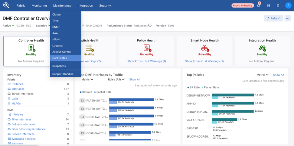
 

Figure 19. Monitoring > Certificates

Public / Private Keys

The Public/Private Keys table displays existing keys, including the Name, Fingerprint Algorithm, and Fingerprint.

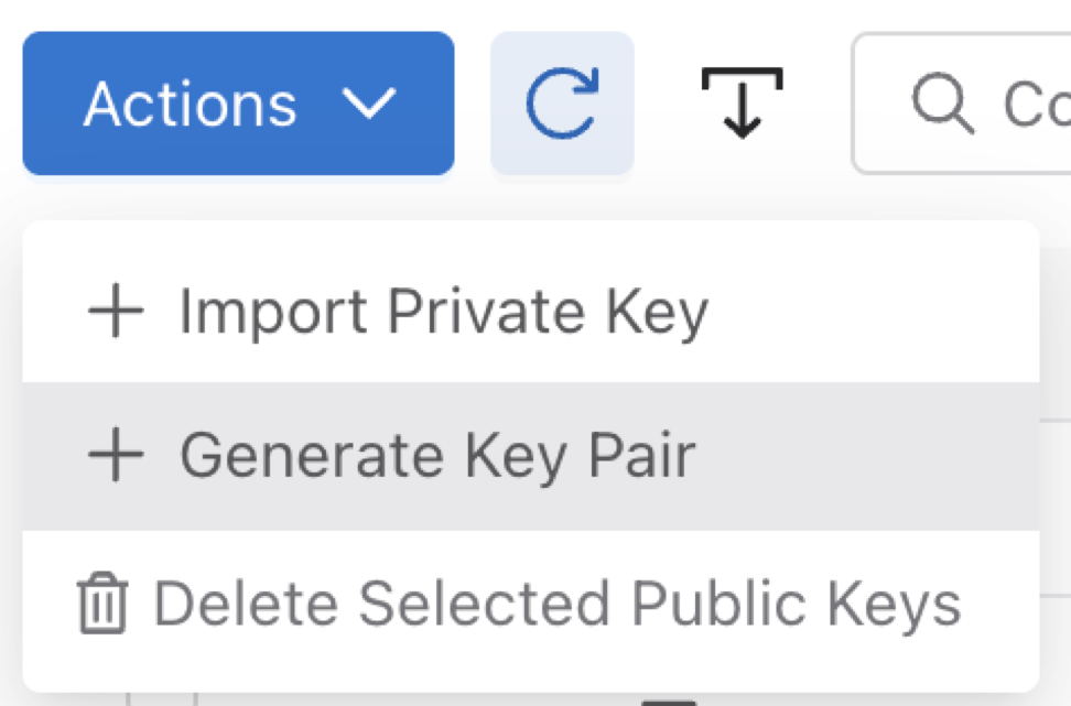
  • Import: Select Import Private key in the Actions drop-down menu to import the Public/Private Key if you have it.

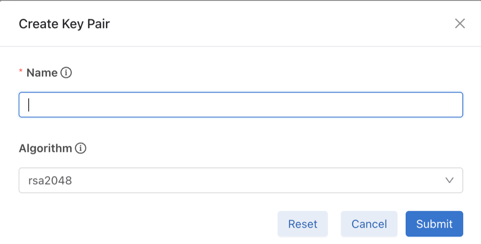
  • Create: Select Generate Key Pair in the Actions drop-down menu to open the creation window.

  • Delete: Select one or more keys using the table checkboxes, then Delete to remove them.
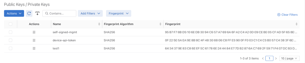
 

Figure 20. Public/Private Keys

Create


Figure 21. Generate Key Pair Action


Figure 22. Create Key Pair Window

Delete Action


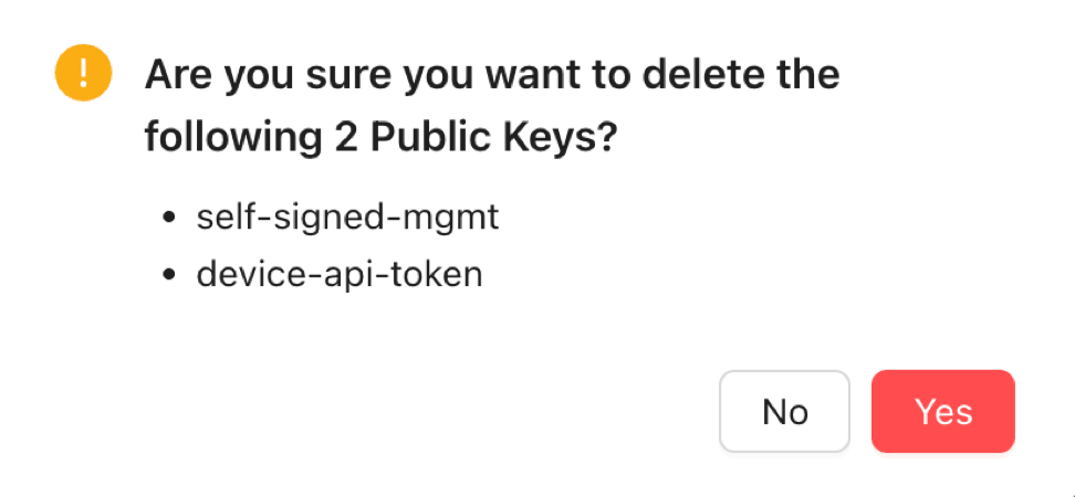
Figure 23. Deletion Confirmation Request

Certificate Signing Requests

The Certificate Signing Requests table displays existing CSRs, including the Name, Fingerprint Algorithm, and Fingerprint.

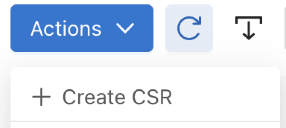
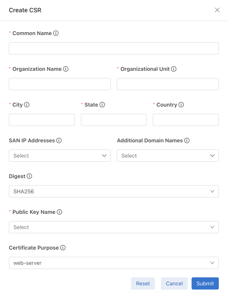
  • Create: Select Create CSR in the Actions drop-down menu to open the creation window.

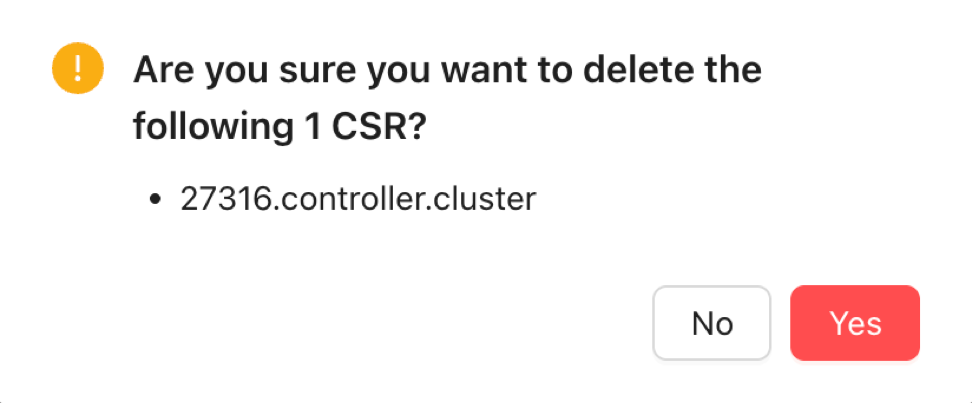
  • Delete: Select one or more CSRs using the table checkboxes, then Delete to remove them.

  • Download: Click on the created CSR’s Actionscolumn and select the Download option to download the CSR file to a local downloads folder. Submit the CSR to the signing authority.

 

Figure 24. Certificate Signing Requests

Create Action


Figure 25. Create CSR Action


Figure 26. Create CSR Window

Delete Action


Figure 27. Deletion Confirmation Request

Certificates

The Certificates table displays existing certificates, including the Name, Fingerprint Algorithm, and Fingerprint.

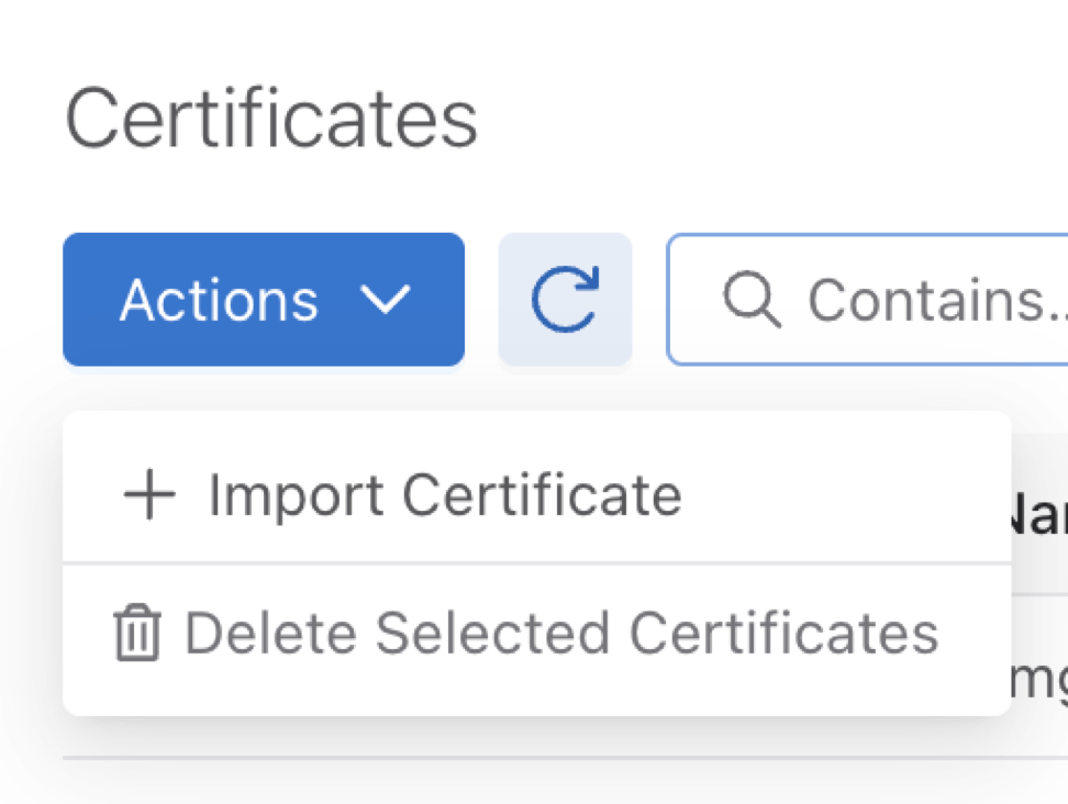
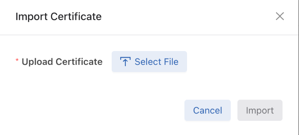
  • Import: Select Import Certificate (Import CA Signed Certificate) in the Actions drop-down menu to open the import window.

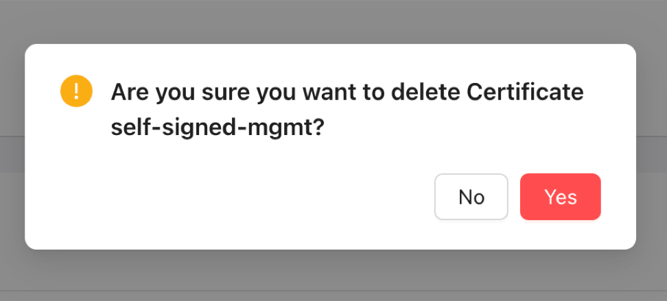
  • Delete: Select one or more certificates using the table checkboxes, then Delete to remove them.

  • Download: Click on the certificate’s Actions column and select the Download option to download the certificate file to a local downloads folder, for backup purposes.

 

Figure 28. Certificate List

Import a Certificate


Figure 29. Import Action


Figure 30. Import Certificate Window

Delete Action


Figure 31. Certificate Deletion Confirmation

DMF UI Certificate

This section displays the active DMF UI certificate.

 

Figure 32. DMF UI Certificate
  • Add or Edit: Select Edit near the title to open the certificate list. Choose the desired certificate and select Submit to apply it.

  • Reset: Select Reset to revert the certificate configuration.
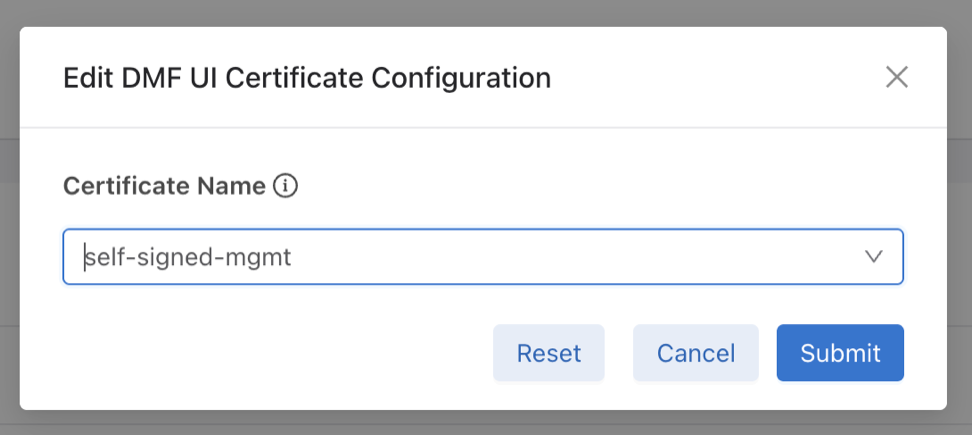
 

Figure 33. Edit DMF UI Certificate Configuration

Managing the Controller HTTP and SSH Ciphers, Protocols, and Data Integrity Algorithms

Use the crypto command to enter the config-crypto submode to configure settings for HTTP and SSH. Use the http and ssh commands in the config-crypto submode to configure the ciphers and protocols. Configure the list of enabled ciphers, protocols, or algorithms by appending to the list.

Use the no version of this command with any keyword to remove the specific cipher, protocol, or algorithm. Use the no version of the command without a keyword to restore the list to the default value. Use the CLI help feature to identify the supported ciphers, protocols, or data integrity (MAC) algorithms.

Configuring HTTP Ciphers

Enter the following commands to configure the ciphers for HTTP:
controller-1(config)# crypto
controller-1(config-crypto)# http
controller-1(config-crypto-http)# cipher <index> <cipher-name>
Note: When you configure a set of ciphers instead of using the default set, please make sure to configure at least one or all the three ciphers mentioned below in addition to your choice. ECDHE-RSA-CHACHA20-POLY1305, ECDHE-RSA-AES128-GCM-SHA256, ECDHE-RSA-AES256-GCM-SHA384.


Example:
controller-1(config)# crypto
controller-1(config-crypto)# http
controller-1(config-crypto-http)# cipher 1 <your choice of cipher-name>
controller-1(config-crypto-http)# cipher 2 <your choice of cipher-name>
controller-1(config-crypto-http)# cipher 3 <your choice of cipher-name>
controller-1(config-crypto-http)# cipher 21 ECDHE-RSA-CHACHA20-POLY1305
controller-1(config-crypto-http)# cipher 22 ECDHE-RSA-AES128-GCM-SHA256
controller-1(config-crypto-http)# cipher 23 ECDHE-RSA-AES256-GCM-SHA384

Configuring HTTP Protocols

Starting in the DANZ Monitoring Fabric 8.4 release, the TLSv1.3 HTTPS protocol is supported. DMF supports TLSv1.3 and TLSv1.2 by default, with the TLSv1.3 protocol preferred for TLS connections.

Enter the following commands to configure the protocols for HTTP:
controller-1(config)# crypto
controller-1(config-crypto)# http
controller-1(config-crypto-http)# protocol <index> <protocol-name>

Configuring SSH Ciphers

Configured SSH ciphers and MAC algorithms on the Controller are pushed to the switches running Switch Light OS via ZTN. With this enhancement, users can also restrict the SSH ciphers and MAC algorithms on the switches.

Enter the following commands to configure the ciphers for SSH:
controller-1(config)# crypto
controller-1(config-crypto)# ssh
controller-1(config-crypto-ssh)# cipher <index> <cipher-name>

Configuring SSH Data Integrity Algorithms

Enter the following command to configure data integrity (MAC) algorithms for SSH:
controller-1(config)# crypto
controller-1(config-crypto)# ssh
controller-1(config-crypto-ssh)# mac <index> <mac-name>

Configuring SSH Host Key Algorithms

Starting from DMF release 8.7.0 it is possible to enable and configure the SSH host key algorithms. Moreover, this capability enables SSH demon (sshd) configurations managed by DMF not to use obsolete SHA-1-based algorithms. DMF imposes the default sshd configuration in the absence of configured SSH host key algorithms and MACs, which excludes SHA-1-based algorithms by default.

Configuration of the SSH host key algorithm is optional.

DMF uses the built-in default set of algorithms if no host key algorithms are explicitly configured. The default set of host key algorithms does not contain any algorithms that use the SHA-1 hash algorithm.

Configuration of SSH host key algorithms follows the same pattern as the existing SSH MACs and cipher configuration under the crypto and ssh submodes.

While in the crypto-ssh submode, specify the host key algorithm to use after an index number.

controller-1> enable
controller-1# configure
controller-1(config)# crypto
controller-1(config-crypto)# ssh
controller-1(config-crypto-ssh)# 
cipher host-key-algorithm mac
controller-1(config-crypto-ssh)# host-key-algorithm 1 rsa-sha2-512
controller-1(config-crypto-ssh)# host-key-algorithm 2 ssh-ed25519


Remove the SSH host key algorithm from the enabled algorithm using the no command option specifying the index number.

After removing all algorithms, DMF uses the default set of algorithms.

controller-1(config-crypto-ssh)# show this

! crypto
crypto
  !
  ssh
    host-key-algorithm 1 rsa-sha2-512
    host-key-algorithm 2 ssh-ed25519
controller-1(config-crypto-ssh)# no host-key-algorithm 2
controller-1(config-crypto-ssh)# show this

! crypto
crypto
  !
  ssh
    host-key-algorithm 1 rsa-sha2-512
controller-1(config-crypto-ssh)#


Show Commands

Specific CLI commands display explicitly configured SSH host key algorithms. These appear in the show running-config output in the crypto ssh section.

controller-1> show running-config crypto ssh
! crypto
crypto
  !
  ssh
    host-key-algorithm 1 rsa-sha2-512
    host-key-algorithm 2 ssh-ed25519
controller-1(config-crypto-ssh)#

In the absence of a host-key-algorithm in the running config, it is implied the default set of algorithms are in effect.

controller-1> show running-config crypto ssh
controller-1(config-crypto-ssh)#

When the CLI is in the crypto-ssh configuration submode, display the current configuration using the show this command:

controller-1(config-crypto-ssh)# show this
! crypto
crypto
  !
  ssh
    host-key-algorithm 1 rsa-sha2-512
    host-key-algorithm 2 ssh-ed25519

Troubleshooting

To troubleshoot issues connecting to DMF over SSH, enable the debug output of the SSH client to view the details.

For example, if using OpenSSH, adding the option ssh -vv displays information about the handshake process.

$ ssh -vv This email address is being protected from spambots. You need JavaScript enabled to view it.
…
debug2: local client KEXINIT proposal
…
debug2: host key algorithms: rsa-sha2-512
…
debug2: peer server KEXINIT proposal
…
debug2: host key algorithms: ssh-ed25519
…
debug1: kex: host key algorithm: (no match)
Unable to negotiate with 10.243.255.120 port 22: no matching host key type found.
Their offer: ssh-ed25519

Default SSH MACs, Ciphers, Keys, and TLS Ciphers

This section specifies the default lists of supported SSH MACs, ciphers, and host-key algorithms in the DANZ Monitoring Fabric as well as the TLS versions and ciphers available by default.
  • Starting from DMF release 8.7.0, the default list of SSH MACs is:
    This email address is being protected from spambots. You need JavaScript enabled to view it.
    This email address is being protected from spambots. You need JavaScript enabled to view it.
    This email address is being protected from spambots. You need JavaScript enabled to view it.
    hmac-sha2-512
    hmac-sha2-256
    This email address is being protected from spambots. You need JavaScript enabled to view it.


  • Starting from DMF release 8.7.0, the SSH ciphers available by default are:
    This email address is being protected from spambots. You need JavaScript enabled to view it.
    This email address is being protected from spambots. You need JavaScript enabled to view it.
    This email address is being protected from spambots. You need JavaScript enabled to view it.
    aes256-ctr
    aes192-ctr
    aes128-ctr


  • Starting from DMF release 8.7.0, the default list of SSH host-key algorithms is:
    This email address is being protected from spambots. You need JavaScript enabled to view it.
    This email address is being protected from spambots. You need JavaScript enabled to view it.
    This email address is being protected from spambots. You need JavaScript enabled to view it.
    This email address is being protected from spambots. You need JavaScript enabled to view it.
    This email address is being protected from spambots. You need JavaScript enabled to view it.
    This email address is being protected from spambots. You need JavaScript enabled to view it.
    This email address is being protected from spambots. You need JavaScript enabled to view it.
    This email address is being protected from spambots. You need JavaScript enabled to view it.
    This email address is being protected from spambots. You need JavaScript enabled to view it.
    ecdsa-sha2-nistp256
    ecdsa-sha2-nistp384
    ecdsa-sha2-nistp521
    This email address is being protected from spambots. You need JavaScript enabled to view it.
    ssh-ed25519
    This email address is being protected from spambots. You need JavaScript enabled to view it.
    rsa-sha2-512
    rsa-sha2-256


  • Starting from DMF release 8.7.0, the default set of supported TLS versions is:
    TLSv1.2
    TLSv1.3


  • Starting from DMF release 8.8.0, the default list of supported TLS ciphers is:
    TLS_AES_256_GCM_SHA384         TLSv1.3  Kx=any   Au=any   Enc=AESGCM(256)            Mac=AEAD
    TLS_CHACHA20_POLY1305_SHA256   TLSv1.3  Kx=any   Au=any   Enc=CHACHA20/POLY1305(256) Mac=AEAD
    TLS_AES_128_GCM_SHA256         TLSv1.3  Kx=any   Au=any   Enc=AESGCM(128)            Mac=AEAD
    TLS_AES_128_CCM_SHA256         TLSv1.3  Kx=any   Au=any   Enc=AESCCM(128)            Mac=AEAD
    ECDHE-ECDSA-CHACHA20-POLY1305  TLSv1.2  Kx=ECDH  Au=ECDSA Enc=CHACHA20/POLY1305(256) Mac=AEAD
    ECDHE-RSA-CHACHA20-POLY1305    TLSv1.2  Kx=ECDH  Au=RSA   Enc=CHACHA20/POLY1305(256) Mac=AEAD
    ECDHE-ECDSA-AES256-GCM-SHA384  TLSv1.2  Kx=ECDH  Au=ECDSA Enc=AESGCM(256)            Mac=AEAD
    ECDHE-RSA-AES256-GCM-SHA384    TLSv1.2  Kx=ECDH  Au=RSA   Enc=AESGCM(256)            Mac=AEAD
    ECDHE-ECDSA-AES128-GCM-SHA256  TLSv1.2  Kx=ECDH  Au=ECDSA Enc=AESGCM(128)            Mac=AEAD
    ECDHE-RSA-AES128-GCM-SHA256    TLSv1.2  Kx=ECDH  Au=RSA   Enc=AESGCM(128)            Mac=AEAD


    Note: The following ciphers have been removed from the default list but are still available for configuration if needed:
    ECDHE-ECDSA-AES128-SHA256    TLSv1.2 
    ECDHE-RSA-AES128-SHA256      TLSv1.2 
    AES128-GCM-SHA256            TLSv1.2 
    AES128-SHA256                TLSv1.2
    ECDHE-ECDSA-AES256-SHA384    TLSv1.2 
    ECDHE-RSA-AES256-SHA384      TLSv1.2 
    AES256-GCM-SHA384            TLSv1.2 
    AES256-SHA256                TLSv1.2

Inherit MAC and Cipher Configuration

This feature provides the ability to mirror the SSH/HTTPS cryptographic configuration of the DMF Controller to the managed appliances (i.e., service nodes and recorder nodes) and the SSH cryptographic configuration of the Controller to the EOS switches.

Using the CLI to Configure SSH and HTTPS

The configuration that a managed appliance or EOS/Switch Light OS switch receives is intended for the Controller itself. Configuring a cipher or message authentication code (MAC) on the Controller will automatically be reflected onto a managed appliance or EOS/Switch Light OS switch.

SSH and HTTPS Cryptographic Configuration Syntax

(config)# crypto
(config-crypto)# ssh
(config-crypto-ssh)# cipher number algorithm
(config-crypto-ssh)# mac number algorithm
(config-crypto-ssh)# http
(config-crypto-http)# cipher number algorithm
(config-crypto-http)# protocol number algorithm


The following is a configuration example using common algorithms.

(config)# crypto
(config-crypto)# ssh
(config-crypto-ssh)# cipher 1 aes256-cbc
(config-crypto-ssh)# mac 1 hmac-sha2-512
(config-crypto-ssh)# http
(config-crypto-http)# cipher 1 AES128-GCM-SHA256
(config-crypto-http)# cipher 2 ECDHE-RSA-CHACHA20-POLY1305
(config-crypto-http)# protocol 2 TLSv1.2


Note: The Controller pushes both the HTTP/TLS and the SSH cryptographic configuration to managed appliances but it only pushes the SSH cryptographic configuration to EOS/Switch Light OS switches.

Verify the Cryptographic Configuration

Check the cryptographic configuration of the Controller using the show running-config command, as shown in the example below, and verify the settings in the crypto section.

# show running-config
.
.
.
! crypto
crypto
!
ssh
cipher 1 3des-cbc
mac 1 hmac-md5
.
.
.

All ciphers/protocols/MACs of the HTTPS/SSH cryptographic configuration supported on the Controller are supported on the managed appliances, with one caveat listed in the Limitations section below. Check the HTTPS/SSH cryptographic configuration by reviewing the running-config of a managed appliance, as shown below for a Recorder Node.

# show recorder-node device rn1 running-config
.
.
.
! crypto
crypto
!
ssh
cipher 1 3des-cbc
mac 1 hmac-md5
.
.
.
Note: EOS does not support all SSH ciphers and MACs that the Controller does.


The following SSH MAC algorithms supported by the Controller are not supported by EOS:
  1. This email address is being protected from spambots. You need JavaScript enabled to view it. (HMAC-MD5 in “encrypt-then-mac” mode)
  2. This email address is being protected from spambots. You need JavaScript enabled to view it. (HMAC-MD5 in “encrypt-then-mac” mode)
  3. This email address is being protected from spambots. You need JavaScript enabled to view it. (HMAC-SHA1 in “encrypt-then-mac” mode)
  4. This email address is being protected from spambots. You need JavaScript enabled to view it. (message authentication code based on universal hashing (UMAC) in “encrypt-then-mac” mode)
  5. This email address is being protected from spambots. You need JavaScript enabled to view it. (UMAC)


The following SSH cipher algorithm supported by the Controller is not supported by EOS:

  • This email address is being protected from spambots. You need JavaScript enabled to view it. (Rijndael in CBC mode)

This difference can be seen when reviewing the running-config of the Controller and the ZTN-generated running-config of an EOS switch:

# show running-config
.
.
.
.
! crypto
crypto
!
ssh
cipher 1 This email address is being protected from spambots. You need JavaScript enabled to view it.
cipher 2 3des-cbc
mac 1 This email address is being protected from spambots. You need JavaScript enabled to view it.
mac 2 This email address is being protected from spambots. You need JavaScript enabled to view it.
.
.
.
.


# show switch switch-name running-config
.
.
.
cipher 3des-cbc
mac This email address is being protected from spambots. You need JavaScript enabled to view it.
.
.
.

Only the ciphers/MACs that are supported get added to the running-config of the EOS switch. To review the disallowed MACs/ciphers when generating the running-config of the switch, use the following show command:

# show fabric warnings feature-unsupported-on-device
# Name  Warning
-|-----|---------------------------------------------------------------------|
1 core1 This email address is being protected from spambots. You need JavaScript enabled to view it. is not a supported cipher on EOS switches
2 core1 This email address is being protected from spambots. You need JavaScript enabled to view it. is not a supported mac on EOS switches

Syslog Messages

No syslog messages are generated when the DMF Controller’s cryptographic configuration is mirrored to the managed appliances and EOS switches.

Limitations

  1. There are limitations to the HTTPS configuration (some options may cause ZTN protocol/communication and controller-to-controller communication failures). The following HTTPS protocol versions are required to be used to avoid communication failures:
    1. TLSv1.2
    2. TLSv1.3
  2. It is not apparent when a cipher/MAC is not reflected onto an EOS switch (due to it being unsupported). To ascertain this scenario, check the Controller's running-config and the switch's ZTN-generated running-config and compare them (alternatively, check the “show fabric warnings” command output to review any generated warnings).
  3. An ECDSA-based cryptographic cipher configuration inherited by the managed appliances will cause a failure in communication with the Controller.

Protocol Access Required to the DMF Controller

Management Plane Access

You can control access to the DMF Controller for specific protocols, and in the case of SSH, you can allow access only from specific IP addresses or subnetworks. The following table summarizes the TCP/UDP protocol ports that DMF uses. The CLI access-list option column shows the options for the ports that can be enabled or disabled using the CLI access-list command (config-controller-access submode). The ports listed are open by default on the Controller, except for SNMP, which is disabled by default.

These ports must also be open on any device, such as a router or firewall, that connects the management console or application to the DMF Controller.
Table 1. List of Open Ports
Protocol Port Application

CLI access-list option

Match criteria
HTTP TCP 80 GUI auto-redirect    
HTTPS TCP 443 GUI remote access gui, applicable to Controller, Service Node, Recorder Node, Analytics Node

Default any, configurable

HTTPS TCP 8443 REST API api, applicable to Controller, Service Node, Recorder Node, Analytics Node

Default any, configurable

ICMP/ICMPv6 ICMP/ICMPv6     selected ICMP types
SNMP UDP 161, 162 SNMP, applicable to Controller, Service Node, Analytics Node snmp

Default none, configurable

SSH TCP 22 CLI remote access ssh, applicable to Controller, Service Node, Recorder Node, Analytics Node

Default any, configurable

syslog UDP 514      
vce-api UDP 7443 vCenter integration vce-api Enabled by default
Note: Be careful when configuring firewall rules for the SSH protocol, which is permitted from all subnetworks by default. The option exists to restrict SSH access to one or more specific subnetworks. However, this denies access from all other subnetworks. If no connectivity from a specified subnetwork is available, accessing the Controller is only through the local console.

Control Plane Access for DMF Controller

The following ports must be open between the DMF Controller and any connected devices. No further configuration is required if all devices are in the same Layer 2 network as the DMF Controller. However, if any DMF nodes or fabric switches connect over a Layer 3 network, these ports must be open on any firewalls or routers that connect the devices to the DMF Controller.
Table 2. DMF Controller
Protocol Port Direction Application In Flows Out Flows
TCP 22 Both Directions SSH Customer

Switches, managed appliances

TCP 49 Out TACACS+  

Customer

TACACS+ server

TCP 53 Out DNS   Customer DNS server
UDP 53 Out DNS   Customer DNS server
UDP 67 Out DHCP   Customer DHCP server
UDP 68 In DHCP Customer DHCP server  
TCP 80 In HTTP Switches  
UDP 123 Both Directions NTP

Switches, Service Node, Recorder Node, Analytics Node

Customer NTP server
UDP 161 In SNMP Customer  
UDP 162 Out SNMP Traps   Customer
TCP 443 In GUI Customer  
UDP 514 Out Syslog   Customer Syslog server
UDP 1813 Out RADIUS  

Default RADIUS accounting port

UDP 5353 In ZTN MDNS

Switches, Service Node, Recorder Node

 
TCP 6379 Out Controller Stats   Analytics Nodes
TCP 6642 Both Directions Cluster Sync Controller HA Controller HA
TCP 6653 In OpenFlow

Switches, Recorder Node, Service Node

 
TCP 7443 In VCE API vCenter API  
TCP 8443 Both Directions

Floodlight

REST API

Customer, Recorder Node

Recorder Node, Service Node

TCP 8443 Out Controller-to-switch traffic   Fabric switches using the Switch Light OS
TCP 8843 In ZTN

Switches, Service Node, Recorder Node

 
TCP 9379 Out

Analytics Node Replicated Redis

  Analytics Node
Note: Starting from DMF release 8.5.0, Controllers use port 8443 to apply configurations to fabric switches using the Switch Light OS. In earlier releases it was port 443. If using Switch Light OS, network administrators must update the firewall configuration to permit traffic on port 8443 between Controllers and fabric switches.
To enable SNMP access to the Controller or to restrict access to the Controller for the REST API, web-based GUI access, or SSH applications, complete the following steps.

Procedure

  1. Enter the controller command from config mode to enter config-controller submode.
    controller-1(config)# controller
    controller-1(config-controller)#
  2. Enter the access-control command from config-controller submode.
    controller-1(config-controller)# access-control
    controller-1(config-controller-access)#
  3. Enter the access-list command from config-controller-access submode followed by the protocol for which you want to configure a rule.
    The protocols for which you can configure rules include the following:
    • api: Enter the config-controller-access-list submode for REST/API access to the Controller.
    • gui: Enter the config-controller-access-list submode for web-based GUI access to the Controller.
    • ns-api: Enter the config-controller-access-list submode to manage NS-API access to the Controller, for example, from OpenStack or vCenter.
    • ssh: Enter the config-controller-access-list submode for SSH access to the Controller.
    • snmp: Enter the config-controller-access-list submode for SNMP access to the Controller.

    By default, the access list for all services except for SNMP is 0.0.0.0/0, which allows access from any IPv4 subnetwork and ::/0, which allows access from any IPv6 subnetwork. For SNMP, the access list is empty, meaning access is not permitted unless specifically enabled. SNMP UDP port 161 is blocked on Controllers and fabric switches by default. You must configure an SNMP access list using the Controller's CLI to communicate using SNMP.

    For example, the following command enters config-controller-access-list submode for the SSH protocol:
    controller-1(config-controller-access)# access-list ssh
                  controller-1(config-controller-access-list)#
    When configuring the following access list on the Controller, the ACL is pushed to all connected switches, and the SNMP ACL is applied to each switch ma1 management interface.
    controller-1(config-controller-access)# access-list snmp
    controller-1(config-controller-access-list)# 1 permit from ::/0
    controller-1(config-controller-access-list)# 2 permit from 10.0.0.0/8
  4. Specify the subnetworks from which access is permitted for the specified protocol. Specify the subnetwork followed by a slash and the number of bits in the subnet mask.
    For example, the following commands allow access to the SSH protocol only from the subnetwork 192.168.1.0:
    controller-1(config-controller-access)# access-list
    ssh controller-1(config-controller-access-list)# 10 permit from 192.168.1.0/24
  5. To view the current firewall configuration for the Controller, enter the show running-config command and see the access-control section.

Protocol Access Required to the DMF Controller - Sync

Sync has been added to the access list. All traffic is permitted for IPv4 (0.0.0.0/0) and IPv6 (::/0) by default. If the active standby Controller High Availability (HA) pair is deployed in different L3 subnets, permitting all traffic for sync services can be a security risk. For a secure connection between the active and standby Controller, the access list for syncing should only permit the active and standby Controller's management IP addresses.

Procedure

  1. Add a rule to permit active Controller management IP address. Do not overwrite the existing default rule for sync. Use a different rule number when adding a new rule for the sync access list. The example below shows how to configure Rule ID 3 (3 permit from 10.240.130.17/32).
    DMF-CTL2(config)# show controller access-control access-list
    #   Access-list  Rule  Action  Source
    -- |----------- |---- |------ |--------- |
    1  api          1     permit  ::/0
    2  api          2     permit  0.0.0.0/0
    3  gui          1     permit  ::/0
    4  gui          2     permit  0.0.0.0/0
    5  ntp          1     permit  ::/0
    6  ntp          2     permit  0.0.0.0/0
    7  snmp         1     permit  0.0.0.0/0
    8  ssh          1     permit  ::/0
    9  ssh          2     permit  0.0.0.0/0
    10 sync         1     permit  ::/0
    11 sync         2     permit  0.0.0.0/0
    12 vce-api      1     permit  ::/0
    13 vce-api      2     permit  0.0.0.0/0
    DMF-CTL2(config-controller-access-list)# controller
    DMF-CTL2(config-controller)# access-control
    DMF-CTL2(config-controller-access)# access-list sync
    DMF-CTL2(config-controller-access-list)# 3 permit from 10.240.130.17/32
    DMF-CTL2(config-controller-access-list)#
  2. Add another rule to permit standby Controller management IP address. Do not overwrite the existing default rule for sync. Use a different rule number when adding a new rule for sync access list. The example below shows how to configure Rule ID 4 (4 permit from 10.240.130.16/32).
    DMF-CTL2(config-controller-access-list)# 4 permit from 10.240.130.16/32
    DMF-CTL2(config-controller-access-list)# show controller access-control access-list
    #  Access-list  Rule  Action  Source
    -- |----------- |---- |------ |----------------|
    1  api          1     permit  ::/0
    2  api          2     permit  0.0.0.0/0
    3  gui          1     permit  ::/0
    4  gui          2     permit  0.0.0.0/0
    5  ntp          1     permit  ::/0
    6  ntp          2     permit  0.0.0.0/0
    7  snmp         1     permit  0.0.0.0/0
    8  ssh          1     permit  ::/0
    9  ssh          2     permit  0.0.0.0/0
    10 sync         1     permit  ::/0
    11 sync         2     permit  0.0.0.0/0
    12 sync         3     permit  10.240.130.17/32
    13 sync         4     permit  10.240.130.16/32
    14 vce-api      1     permit  ::/0
    15 vce-api      2     permit  0.0.0.0/0
    DMF-CTL2(config-controller-access-list)#
  3. Remove the default permit entry.
    DMF-CTL2(config-controller-access-list)# no 1 permit
    DMF-CTL2(config-controller-access-list)# no 2 permit
    DMF-CTL2(config-controller-access-list)# show controller access-control access-list
    #  Access-list  Rule  Action  Source
    -- |----------- |---- |------ |---------------- |
    1  api          1     permit  ::/0
    2  api          2     permit  0.0.0.0/0
    3  gui          1     permit  ::/0
    4  gui          2     permit  0.0.0.0/0
    5  ntp          1     permit  ::/0
    6  ntp          2     permit  0.0.0.0/0
    7  snmp         1     permit  0.0.0.0/0
    8  ssh          1     permit  ::/0
    9  ssh          2     permit  0.0.0.0/0
    10 sync         3     permit  10.240.130.17/32
    11 sync         4     permit  10.240.130.16/32
    12 vce-api      1     permit  ::/0
    13 vce-api      2     permit  0.0.0.0/0
    DMF-CTL2(config-controller-access-list)#
  4. Verify cluster state using show controller details and make sure cluster state is redundant.
    DMF-CTL2(config)# show controller details
    Cluster Name : DMF-7050
    Cluster UID : a5de38214971de42aa7b51b96ac7345f4f228b20
    Cluster Virtual IP : 10.240.130.18
    Redundancy Status : redundant
    Redundancy Description : Cluster is Redundant
    Last Role Change Time : 2022-11-05 00:56:04.862000 UTC
    Cluster Uptime : 2 months, 1 week
    # IP            Hostname @ Node Id Domain Id State   Status    Uptime
    -|-------------|--------|-|-------|---------|-------|---------|---------------|
    1 10.240.130.17 DMF-CTL2 * 22049           1 active  connected 2 weeks, 2 days
    2 10.240.130.16 DMF-CTL1   27671           1 standby connected 2 weeks, 2 days
    ~~~~~~~~~~~~~~~~~~~~~~~~~~~~~~~~~~~~~~~~~~~~~~~~~~~~~~~ Failover History ~~~~~~~~~~~~~~~~~~~~~~~~~~~~~~~~~~~~~~~~~~~~~~~~~~~~~~~
    # New Active Time completed                 Node  Reason                Description
    -|----------|------------------------------|-----|---------------------|-------------------------------------------------------|
    1 22049      2022-11-05 00:55:35.994000 UTC 22049 cluster-config-change Changed connection state: cluster configuration changed
    DMF-CTL2(config)#

    Removing default rules before adding the new sync access-list rules can break Controller cluster communication. To recover from this, please refer to Controller Cluster Recovery.

Control Plane Access for DMF Switches

The following ports must be open for DMF Switches to communicate with DMF Controller, Analytics Node, and other services (e.g., NTP, DHCP, etc.). No further configuration is required if all devices are in the same Layer 2 network as the DMF Controller. However, if any DMF Controller and fabric switches connect over a Layer 3 network, these ports must be open on any firewalls or routers that connect the devices to the DMF Controller.
Table 3. DMF Switch
Protocol Port Direction Application In Flows Out Flows
TCP 22 In SSH Customer, DMF Controller  
TCP/UDP 53 Out DNS   Customer DNS Server
UDP 67 Out DHCP   Customer DHCP Server
UDP 68 In DHCP Customer DHCP Server  


TCP


443*


In


cAPI*


DMF Controller
 
UDP 123 Out NTP   Customer NTP Server
UDP 161 In SNMP Customer  
UDP 162 Out SNMP Trap   Customer
UDP 514 Out Syslog   Customer Syslog Server
UDP 5353 Out ZTN MDNS   DMF Controller


TCP


6030


In


Telemetry*


UDP


6343


Out


sFlow®*


Analytics Node
UDP 6380 Out Control Packets   Analytics Nodes
TCP 6653 Out OpenFlow   DMF Controller
TCP 8443 In BigDB DMF Controller  
TCP 8843 Out ZTN   DMF Controller

Use Port 443 as Default cAPI Port

Starting from DMF Release 8.9.0, the Command-API (cAPI) client on the DMF Controller utilizes port 443 for EOS connectivity. Follow the procedure below when upgrading from using port 80.

Show Commands

Verify the HTTPS protocol and the port assignment on core switches by executing the following command:

dmf-controller-1# show switch core1 running-config | grep https
protocol https port 443

Pre-upgrade Validation

Upgrading from previous DMF versions that depend on port 80 requires configuring HTTPS on port 443 on EOS switches to maintain the ZTN functionality. A cAPI client can use port 443 for connectivity after the upgrade.

The bigtap_eos_https_port_validate utility validates this configuration as a pre-upgrade step, ensuring port availability before the upgrade rather than after it:

  • Action: Verifies port 443's availability on EOS switches.

  • Reason: Necessary for post-upgrade cAPI client connectivity.

  • Impact: Inaccessible ports result in ZTN initialization failure.

A pre-validation failure triggers the following upgrade launch error:

POST /api/v1/rpc/controller/os/upgrade/launch
Response 
{  
   "description": "Error launching upgrade: launch aborted: 
validation failed: EOS devices:   <switch_names> cannot be 
upgraded, the https port 443 is not open for connection, fix 
and retry the upgrade- Completed upgrade state cleanup on 
exception",
   "error-code": 500
}

Troubleshooting

Perform the following validation procedures to resolve ZTN state issues:

  • Verify ZTN Configuration Synchronization - Confirm the configuration sync status on managed devices by executing the following command:

    dmf-controller-1# show managed-devices all zerotouch 
    # Name  Device                        Ip address     Platform                   Serial number                    Last update                    Zerotouch state 
    -|-----|-----------------------------|--------------|--------------------------|--------------------------------|------------------------------|---------------
    1 core1 52:54:00:58:86:3a (Linux KVM) 10.243.254.71  x86-64-bigswitch-bs3240-r0 SN-MAC-5c:16:c7:1d:bb:97         2025-09-19 12:19:37.455000 UTC ok
    2 core2 52:54:00:5f:f9:a8 (Linux KVM) 10.243.254.214 x86_64-cloudeos-eos        49E66AEBA5054CA1D825B37D5B534FF6 2025-09-19 12:19:48.985000 UTC ok
    3 rn1   52:54:00:88:17:cc (Linux KVM) 10.243.254.38                             Not Specified                    2025-09-19 12:19:33.533000 UTC ok
    4 sn1   52:54:00:c6:66:a7 (Linux KVM) 10.243.253.62                             Not Specified                    2025-09-19 12:19:32.534000 UTC ok
    
  • Verify the EOS HTTPS Server Status - Validate that the HTTPS server on an EOS switch is active and listening on port 443 using the following command:

    core1(config)# show management api http-commands
    Enabled: Yes
    HTTPS server: running, set to use port 443
    HTTP server: running, set to use port 80
    Local HTTP server: shutdown, no authentication, set to use port 8080
    Unix Socket server: shutdown, no authentication
    VRFs: default
    Hits: 62
    Last hit: 0:00:10 ago
    Bytes in: 11775
    Bytes out: 9785
    Requests: 58
    Commands: 86
    Duration: 8.851 seconds
    SSL Profile: none
    FIPS Mode: No
    QoS DSCP: 0
    Session Timeout: 1440 minutes
    Log Level: none
    CSP Frame Ancestor: None
    TLS Protocols: 1.0 1.1 1.2 1.3
    

Control Plane Access for DMF Service Node

The following ports must be open for the DMF Service Node to communicate with the DMF Controller, Analytics Node, and other services (e.g., NTP, DHCP, etc.). No further configuration is required if all devices are in the same Layer 2 network as the DMF Controller. However, if the DMF Controller and Service Nodes connect over a Layer 3 network, these ports must be open on any firewalls or routers.

Table 4. DMF Service Node
Protocol Port Direction Application In Flows Out Flows
TCP 22 In SSH Customer, DMF Controller  
TCP 49 Out TACACS+  

Customer TACACS+ Server

TCP/UDP 53 Out DNS   Customer DNS Server
UDP 67 Out DHCP   Customer DHCP Server
UDP 68 In DHCP Customer DHCP  
UDP 123 Out NTP   Customer NTP Server
UDP 161 In SNMP Customer  
UDP 162 Out SNMP Trap  

Customer SNMP Trap Server

UDP 514 Out Syslog   Customer Syslog Server
UDP 1812 Out

Default RADIUS

Authentication port

  Customer RADIUS Server
UDP 1813 Out

Default RADIUS

Accounting port

  Customer RADIUS Server
UDP 5353 Out ZTN MDNS   DMF Controller
TCP 6030 In Telemetry    
TCP 6634 In Telemetry    
TCP 6653 Out OpenFlow   DMF Controller
TCP 8443 Both Direction

Floodlight REST

API

DMF Controller DMF Controller
TCP 8843 Out ZTN   DMF Controller

Control Plane Access for DMF Recorder Node

The following ports must be open between the DMF Recorder Node and any connected devices. No further configuration is required if all devices are in the same Layer 2 network as the DMF Recorder Node. However, if the DMF Controller, Analytics Node, or fabric switches connect over a Layer 3 network, these ports must be open on any firewalls or routers that connect the devices to the DMF Recorder Node.

Table 5. DMF Recorder Node
Protocol Port Direction Application In Flows Out Flows
TCP 22 In SSH Customer, DMF Controller  
TCP 49 Out TACACS+  

Customer TACACS+ Server

TCP/UDP 53 Out DNS   Customer DNS Server
UDP 67 Out DHCP   Customer DHCP Server
UDP 68 In DHCP Customer DHCP Server  
UDP 123 Out NTP   Customer NTP Server
UDP 161 In SNMP Customer  
UDP 162 Out SNMP Trap  

Customer SNMP Trap Server

TCP 443 In

Stenographer

Query API

Customer, DMF Controller  
UDP 514 Out Syslog   Customer Syslog Server
UDP 1812 Out

Default RADIUS

Authentication port

  Customer RADIUS Server
UDP 1813 Out

Default RADIUS

Accounting port

  Customer RADIUS Server
TCP 2049 Both NFS   Customer NSF Server
UDP 2049 Both NFS   Customer NFS Server
UDP 5353 Out ZTN MDNS   DMF Controller
TCP 6653 Out OpenFlow   DMF Controller
TCP 8443 Both Direction

Floodlight REST

API

DMF Controller DMF Controller
TCP 8843 Out ZTN   DMF Controller

Control Plane Access for Analytics Node

The following ports must be open between the Analytics Node and any connected devices. No further configuration is required if all devices are in the same Layer 2 network as the Analytics Node. However, if the Analytics Node connects over a Layer 3 network, these ports must be open on any firewall or router.

Table 6. DMF Analytics Node
Protocol Port Direction Application In Flows Out Flows
TCP 22 In SSH Customer  
TCP 25   SMTP  

Analytics Nodes to Mail

Server

TCP 49 Out TACACS+  

Customer TACACS+ Server

TCP/UDP 53 Out DNS   Customer DNS Server
UDP 67 Out DHCP   Customer DHCP Server
UDP 68 In DHCP Customer DHCP Server  
UDP 123 Out NTP   Customer NTP Server
UDP 161 In SNMP Customer  
UDP 161 In SNMP

from Analytics Nodes to

DMF switch

 
UDP 162 Out SNMP Trap   Customer
UDP 162 Out SNMP Trap   From Analytics Nodes to DMF switch
TCP 443 In GUI Customer  
TCP 467   SMTP   Analytics to Mail Server
UDP 514 Out Syslog   Customer Syslog Server
UDP 1812 Out

Default RADIUS

Authentication port

  Customer RADIUS Server
UDP 1813 Out

Default RADIUS

Accounting port

  Customer RADIUS Server
UDP 2055 In NetFlow v5

DMF Service Nodes and

Switches

 
UDP 4739 In

IPFIX & NetFlow

v9

DMF Service Nodes and

Switches

 
TCP 5043 Both Direction Active Directory

Customer Active Directory

Server

Customer Active Directory

Server

UDP 6343 In

sFlow®*

DMF Switches  
TCP 6379 Both Direction Controller Stats

Controller to Analytics

VIP

 
UDP 6380 In Control Packets DMF Switches  
TCP 6642 Both Direction

Analytics Cluster

sync

HA controller HA controller
TCP 8443 Both Direction

Floodlight REST

API

Customer Managed Appliances
TCP 9379 Both Direction Replicated Redis

DMF Controller to Analytics Node VIP

 
TCP 9379 Out Analytics Node

Replicated Re- dis Server (for dpid.port -> Filter Name)

  Analytics Node
* Starting from DMF release 8.9.0 the cAPI port on the Controller is automatically changed to 443 for EOS connectivity. It used to be 80 in prior releases.
* Port to be opened on firewalls for Arista switches running EOS to communicate with the DMF Controller.
* sFlow® is a registered trademark of Inmon Corp.

Using Authentication, Authorization, and Accounting

This chapter describes how to manage administrative access to the DANZ Monitoring Fabric (DMF) Controller using local groups and users (RBAC) and AAA servers in general, and it also provides specific configuration for TACACS+ or RADIUS servers.


Overview

Access privileges to the DANZ Monitoring Fabric (DMF) Controller are associated with groups. Each user assigned to the group obtains the access permissions associated with the group. The current version of DMF supports the following two groups:
  • Admin Group: Root privileges with access to all modes, including debug modes.
  • Read-Only: Read-only administrative access.
DMF also supports communication with a remote AAA server. All authentication, authorization, and accounting functions are set to local by default. The general options that control where these functions occur are:
  • Local only: The accounts on the remote AAA server are ignored, using only the local database accounts.
  • Local primary and remote backup: The accounts on the local database are used first. If the account is not found locally, DMF uses the database on the remote server.
  • Remote only: Authentication and authorization do not fall back to local for users other than the admin and recovery accounts, no matter what happens.
  • Remote primary and local backup: Uses the accounts on the remote AAA database first. If the remote server is unavailable, DMF uses the local database accounts.
Note: The admin and recovery user accounts are special accounts that cannot be authenticated remotely using RADIUS or TACACS+. These accounts are always authenticated locally to prevent administrative access from being lost in case a remote AAA server is unavailable. The following list summarizes the options available for each function:
The following list summarizes the options available for each function:
  • Accounting: local, local and remote, or remote.
  • Authentication: local, local then remote, remote then local, or remote.
  • Authorization: local, local then remote, remote then local, or remote.
Note: Authorization falls back to local only if remote authorization fails because the remote AAA server is unreachable.

For information about using AAA with remote servers to manage administrative access to the DMF Controller, refer to the Configuring AAA to Manage DMF Controller Access section.

Using Local Groups and Users to Manage DMF Controller Access

Administrative access to the monitoring fabric is managed by assigning interfaces to groups and then assigning user accounts to the group, which can then view and use the assigned interfaces.

Viewing Existing Groups and Users

To view the current allocation and assignment of groups and resources, enter the following command from any CLI mode on the active DANZ Monitoring Fabric (DMF) Controller.

To use the GUI to manage groups and users, select Security from the DMF GUI main menu.

Figure 1. Security


The system displays the Security page menu options.
  • Users
  • Groups
  • Sessions
  • Login/Lockout History
  • HTTP/SSH Ciphers

Groups

Displays the following preconfigured default groups on the DMF Controller:
  • admin group: Provides full administrative access to all interfaces. Global configuration options, such as assigning a role to a switch or interface, must be performed by the admin user.
  • read-only group: Provides access to view and monitor fabric activity and switch configuration for all interfaces but does not allow changing configuration or clearing statistics.

All switch interfaces are assigned to both default groups. The admin user has read, use, and configure access to all the interfaces. Any user added to the read-only group has read-only access to all the interfaces.

You can define a new group, in which case a user added to the group will be a restricted user with privileges to view and use only the interfaces assigned to the group.

Using the GUI to Manage User Accounts & Security Groups

To add a user to a group or to add a group, complete the following steps.
Add users from the main Security page or the following page when selecting Security > Users from the DMF GUI main menu.
Figure 2. Security > Users


  1. Select Actions > + Add User in the Users section.
    The system displays the Add User dialog.
    Figure 3. Add User


  2. Click Submit.
  3. To edit a user, click the Actions > Edit icon for the requisite Username.
  4. To delete a user, select Actions > Delete Selected Users .
  5. To add a Security Group, select Security > Groups in the Groups section.
    Figure 4. Security Groups
     
  6. Select Actions > + Create Group .
    The system displays the Create Group menu.
    Figure 5. Create Group


  7. Enter a name for the group and all other required group settings, including:
    • Category Access
      • Default - Inherit, Does Not Elevate, Read Only, Read Write (drop-down)
      • AAA - Inherit, Does Not Elevate, Read Only, Read Write (drop-down)
      • App Log - Inherit, Does Not Elevate, Read Only, Read Write (drop-down)
      • Sysops - Inherit, Does Not Elevate, Read Only, Read Write (drop-down)
      • Time - Inherit, Does Not Elevate, Read Only, Read Write (drop-down)
      • Telemetry - Inherit, Does Not Elevate, Read Only, Read Write (drop-down)


    • Role Based Access Control (RBAC)
      • Policy - Policies Configured, + Add Policy
      • Service - Service Configured, + Add Service
      • Switch Interface - Switch Interface Configured, + Add Switch Interface
      • Recorder Node - Recorder Nodes Configured, + Add Recorder Node


  8. When complete, click Create. The table displays the new group.
  9. To edit a security group, click the Actions > Edit icon for the requisite Group Name.
  10. To delete a security group, select Actions > Delete Selected Groups .

Using the CLI to Manage Groups and User Accounts

To add a group, enter the group command from config mode, as in the following example:
controller-1(config)# group dc-group
To associate users with a group, enter the associate command from config-group mode, as in the following example:
controller-1(config-group)# associate user bob
controller-1(config-group)# associate user susan
To associate interfaces with the group, enter the associate command for each interface, as in the following example:
controller-1(config-group)# associate switch DMF-FILTER-SWITCH-1 interface TAP1-ethernet1

To associate other resources with the group, use the following options with the associate command:

[no]associate object{policy|service}<object-name>
[created-by<object-creator>[created-on<date-and-time>]]

Enter the show group command to display the currently configured groups and users.

To display the group configuration in the current running-config, enter the show running-config group command, as in the following example:
controller-1# show running-config group
! group
group admin
associate user admin
group dmf-qa
associate switch DMF-FILTER-SWITCH-1 interface ethernet1
associate switch DMF-FILTER-SWITCH-1 interface ethernet2
associate switch DMF-FILTER-SWITCH-1 interface ethernet25
associate switch DMF-FILTER-SWITCH-1 interface ethernet26
associate user test1
group read-only
To use the CLI, enter the following commands from config mode.
controller-1(config)# user bob
controller-1(config-local-user)# full-name Robert Smith
controller-1(config-local-user)# password
Password:
Re-enter:
controller-1(config-local-user)# group admin
controller-1(config-group)# associate user bob
controller-1(config-group)# show user
#  User name  Full name      Groups
- |--------- |------------- |--------- |
1  admin      Default admin  admin
2  bob        Robert Smith   admin
Enter the no user command from config mode to delete a user, as in the following example.
node1(config)# no user bob
controller-1(config)# show user
#  User name  Full name      Groups
- |--------- |------------- |------- |
1  admin      Default admin  admin
To add a read-only user, run the following commands from config mode.
controller-1(config)# user john
controller-1(config-local-user)# full-name John Smith
controller-1(config-local-user)# password
Password:
Re-enter:
controller-1(config-local-user)# group read-only
controller-1(config-group)# associate user john
controller-1(config-group)# show user
#  User name  Full name      Groups
- |--------- |------------- |--------- |
1  admin      Default admin  admin
2  bob        Robert Smith   admin
3  john       John Smith     read-only

Changing User Passwords

To change the password for the admin user or other user accounts, select the Actions > Edit icon for the requisite Username from the Security > Users page.
Figure 6. Security Users


Note: Entering a new password will overwrite the existing one. Leaving it blank retains the original password.


Figure 7. Change Password


Type the new password, confirm it, and click Submit.

Password Reset

Resetting the Password for the Recovery User

To reset the password for the recovery user, please follow one of the following procedures. Perform these steps on each cluster Controller as resetting the password of the recovery user on one Controller won't change it for the recovery user on the other Controller.

  1. Using the Controller’s bash:
    1. Go to the Controller bash by executing debug bash.
    2. Execute sudo passwd recovery.
      admin@controller-1:~$ sudo passwd recovery
      New password:
      Retype new password:
      passwd: password updated successfully
      admin@controller-1:~$
  2. From the recovery login account login:
    For this to work, the current password for the recovery user is required.
    recovery@controller-1:~$ passwd recovery
    Changing password for recovery.
    Current password:
    New password:
    Retype new password:
    passwd: password updated successfully
    recovery@controller-1:~$
  3. Using the API /api/v1/rpc/controller/os/action/system-user/reset-password:
    The API call below will reset the recovery user's password to AdminAdmin. The example below uses curl initiated from a Linux host, but any RESTful API client can call the API.
    curl -g -H "Cookie: session_cookie=<session_cookie>" 
    'https://<controller IP>:8443/api/v1/rpc/controller/os/action/system-user/reset-password'
    -d '{"user-name" : "recovery","password" : "AdminAdmin"}' -X POST              
Resetting Password for admin and Other Local Users

To reset the password for admin and other local users, log in to the Controller using recovery user credentials. Use the floodlight-reset-password command to reset the user’s password.

The example below example resets the admin user’s password.
recovery@controller-1:~$ floodlight-reset-password --user admin
Enter new admin password:
Re-enter new admin password:
Password updated for user admin
recovery@controller-1:~$
The example below resets the password for the guest account, a read-only group user.
recovery@controller-1:~$ floodlight-reset-password --user guest
Enter new guest password:
Re-enter new guest password:
Password updated for user guest
recovery@controller-1:~$

Authentication with a User Token and REST API

Use the access-token command to create a long-lived token for authentication with external scripting, such as RESTful API. The token can be deleted (repudiated) at any time. DMF preserves a hashed version of the token in the running-config.

The following example shows an access token with the key sam assigned to the user fred.
controller-1(config)# user fred
controller-1(config-user)# access-token sam
access-token : Y9yVwLawjJ03lSthnBKVh3XeplaJ6sSE

The system replies with the session cookie for use in the REST API.

To display the hashed version of the session cookie, enter the show this command or show running-config fred.
controller-1(config-user)# show this
! user
user fred
access-token sam 459d1d5e0bc42c5bbbee091a984e2807592d11d8a5d4cbac110d32da3f0e436c 2018-01-
08T15:44:02.353Z
hashed-password
method=PBKDF2WithHmacSHA512,salt=N9E9jaPIFTc_ZO9Oq0gd4A,rounds=25000,ph=true,
7eCf1PGAYqUw53vJ2bsGpSVEU5-D6ix5sHufFUi3gFr3AHB4Jqj2eLNZzoo66y_qIRFOOOL8nc5oG5i1gJ1FxA
controller-1(config-user)#
The session cookie does not appear in the running-config; the hashed session cookie instead appears. Because the cookie is in the running-config, it persists over upgrade. To remove the token, enter the no access-token command, as in the following example:
controller-1(config-user)# no access-token sam

Configuring AAA to Manage DMF Controller Access

Authentication, Authorization, and Accounting (AAA) is a general standard for controlling and auditing access to network resources. Various implementations are possible using technologies such as LDAP, RADIUS, Kerberos, TACACS+, or a local database.

The current version of DANZ Monitoring Fabric (DMF) supports AAA using a local database on the Controller node or with a remote TACACS+ or RADIUS server. All authentication, authorization, and accounting functions are set to local by default.
Note: The DMF Controller does not support pushing RADIUS and TACACS+ configurations to EOS switches. The DMF Controller only supports pushing TACACS+ configurations to Switch Light OS switches.

Authentication and authorization occur only once, and whatever privileges are associated with the first account found are used. Configuring options separately for authentication and authorization is possible, but Arista Networks recommends using the same settings for simplicity.

When one or more remote AAA servers are available, the best practice is to enable remote logging as the primary authorization method. The local database is only used if no remote server responds to the authorization request before the timeout. By default, the timeout is five seconds per server, with a maximum total timeout of 25 seconds for up to four remote servers.
Note: The admin and recovery user accounts are special accounts that cannot be authenticated remotely using RADIUS or TACACS+. These accounts are always authenticated locally to prevent administrative access from being lost in case a remote AAA server is unavailable.
Note: If the user fails to be authorized by any AAA server, the user account can be authorized as a member of the default group and chosen from the Default Group selection list. The options are admin or read-only when configuring the latter group.

DMF supports AAA services using RADIUS and TACACS+ servers using up to four servers of each type. The default timeout for each AAA server is five seconds, which was previously 30 seconds in earlier releases. The total aggregate timeout for all configured servers is 20 seconds.

By default, the Controller waits five seconds before trying the next server or falling back to the local services provided by the Controller database if that is the configuration. You can change the default timeout, but the maximum aggregated time for all the servers is 25 seconds. Five servers are supported only with a default timeout of five seconds or less.

Using the GUI - Enabling Remote AAA Services

GUI Procedure

To manage the configuration of AAA settings on the DMF Controller, select Maintenance > AAA .
Figure 8. AAA Settings Page


AAA configuration tabs and features include:
  • Accounting
  • Authentication
  • Authorization
  • RADIUS
  • TACACS+
  • Audit Logging

This page supports identifying up to five destination TACACS+ or RADIUS servers, configuring the server secret, and specifying a timeout.

Accounting

To log accounting log messages to a remote server, click Accounting > Edit in the Configuration section.
Figure 9. Accounting Settings


By default, DMF saves accounting logs on the local Controller. If local logging is disabled, these logs will not be available for analysis locally. To send the accounting logs to a remote server, select the Order preference:
  • Local Only - Default.
  • Remote Only - Enter a Remote Method, TACACS or RADIUS from the drop-down list.
  • Local Before Remote - Enter a Remote Method, TACACS or RADIUS from the drop-down list.
  • Remote before Local - Enter a Remote Method, TACACS, or RADIUS from the drop-down list.
Click Submit.
Tip: Use the Reset button to return to the default setting, if required.

Authentication

To configure the authentication method, click Authentication > Edit in the Configuration section.

Figure 10. Authentication Settings


Select the Authentication Order preference:

  • Local Only - Default.
  • Remote Only - Enter a Remote Method, TACACS or RADIUS from the drop-down list.
  • Local Before Remote - Enter a Remote Method, TACACS or RADIUS from the drop-down list.
  • Remote before Local - Enter a Remote Method, TACACS or RADIUS from the drop-down list.

Lockout Policy Mode

Configuration for the time-based user lockout policy. In no-lockout mode, the configuration of this container is ignored, and lockout is disabled. In lockout-remote mode, this container's values (or, in their absence, the defaults) dictate the lockout behavior.

Select the desired Lockout Policy Mode:
  • No Lockout
  • Lockout Remote
Click Next and set the Password Compliance Requirements from the drop-down list:
  • None
  • NIST-800-63B
  • Custom-Check - Enter the requirements for the detailed password (min/max, etc.).
  • No-Check

Click Submit.

Authorization

To use a remote server for authorization, click Authorization > Edit in the Configuration section.

Select the Authorization preference:
Figure 11. Authorization Settings


Select the Authorization Order preference:

  • Local Only - Default.
  • Remote Only - From the drop-down list.
  • Local Before Remote - From the drop-down list.
  • Remote before Local - From the drop-down list.

Click Submit.

RADIUS

To configure RADIUS refer to the Using RADIUS for Managing Access to the DMF Controller section.

TACACS+

To configure TACACS+ refer to the Using TACACS+ to Control Access to the DMF Controller section.

Audit Logging

To configure the audit logging method, click Audit Logging > Edit in the Configuration section.
Figure 12. Audit Logging


Set the type of audit logging of request leaf values; if no value is specified, request leaf values will not be audit logged.

Select the Log Request Leaf Values from the drop-down list:
  • None - Default.
  • Record All Request Values

Click Submit.

Using the CLI - Enabling Remote AAA Services

CLI Procedure

Use the aaa authorization role default command to assign a default role to the current account. DMF uses the default group if authentication on a remote server is successful but no role is specifically assigned. This command does not apply to local authorization or authentication. If a local user is not associated with a group on the Controller, login is not allowed.
Note: Use the authorization role default admin command carefully because the effect is to provide every user account that authenticates successfully on a remote server with admin-level privileges unless the user account is specifically assigned to a different group.

Time-based User Lockout

Starting in the DMF 8.0 release, DANZ Monitoring Fabric supports time-based user lockout functionality. Users are locked out for ‘t2’ time when attempting with ‘n’ incorrect passwords within ‘t1’ time.

Locked-out users must either be cleared of lockout or wait for the lockout period to expire before attempting another login with a correct password. The feature is disabled by default.

To enable, use the following command:
aaa authentication policy lockout failure <number of failed attempts> window <within t1 time>
duration <lockout for t2 time>
  • The value range for ‘failure’ is 1 to 255.
  • The value range for ‘window’ and ‘duration’ is 1 to 4294967295 seconds (2^32-1).
The example below locks out any user out for 15 minutes when attempting three incorrect logins within 3 minutes.
controller-1(config)# aaa authentication policy lockout failure 3 window 180 duration 900
Note:
  • This feature affects only remote logins such as SSH/GUI/REST API using username/password. Console-based login and password-less authentications such as SSH keys, Single Sign-on, and access tokens are unaffected. Locked-out users can still access the Controller via console/password-less authentication.
  • The feature is node-specific concerning the functionality, i.e., if user1 is locked out of accessing the active Controller in the cluster, they can log in to the standby Controller with the correct password and vice versa. Lockout user information is not persistent across Controller reboot/fail-over.


To view if a user is locked out, admin-group users can run the following command:
show aaa authentication lockout


controller-1# show aaa authentication lockout
User name Host           Failed Logins  Lockout Date                    Lockout Expiration
--------- |------------ |------------- |------------------------------  |------------------------------ |
admin     10.240.88.193  1              2020-09-08 16:07:36.283000 PDT  2156-10-15 22:35:51.283000 PDT
To clear the lockout for a user, admin-group users can run the following command:
clear aaa authentication lockout user <username>
To clear all the locked-out users use the following command:
clear aaa authentication lockout
The following example shows how to clear a locked-out admin user:
controller-1# clear aaa authentication lockout user admin
controller-1# show aaa authentication lockout
None.

A Recovery user will also be locked out if attempting with incorrect passwords.

To check if the user is locked out, use the ‘pam_tally2’ tool:
admin@controller-1:~$ sudo pam_tally2 -u recovery
Login Failures Latest failure From
recovery 9 09/08/20 16:16:04 10.95.66.44
To reset the lockout for the user, use the following command:
admin@controller-1:~$ sudo pam_tally2 --reset --user recovery
Login Failures Latest failure From
recovery 9 09/08/20 16:16:04 10.95.66.44
admin@controller-1:~$ sudo pam_tally2 -u recovery
Login Failures Latest failure From
recovery
Note: The window parameter does not apply to the Recovery user login as the ‘pam_tally2’ tool does not support it.

Using TACACS+ to Control Access to the DMF Controller

Use remote Authentication, Authorization, and Accounting (AAA) services employing a TACACS+ server to control administrative access to the switch CLI. The following table lists the accepted Attribute-Value (AV) pairs:

Table 1. Accepted Attribute-Value (AV) Pairs
Attributes Values
BSN-User-Role admin
  read-only
  bigtap-admin
  bigtap-read-only
Note: The remotely authenticated admin and bigtap-admin users and the read-only and bigtap-read-only users have the same privileges. The bigtap-admin and bigtap-read-only values are supported to allow the creation of DMF-specific entries without affecting the admin and read-only TACACS+ server entries.


A remotely authenticated admin user has full administrative privileges. Read-only users on the switch must be remotely authenticated. Read-only access is not configurable for locally authenticated user accounts on the switch.

Read-only users can only access login mode, from where they can view most show commands, with some limitations, including the following:
  • TACACS+, SNMP, and user configuration are not visible to the read-only user in the output from the show running-config command.
  • show snmp, show user, and show support commands are disabled for the read-only user.
    Note: Local authentication and authorization take precedence over remote authentication and authorization.


Configure privileges on the remote TACACS+ server using the following attribute-value pairs:
  • Supported attribute name: BSN-User-Role
  • Supported attribute values: admin, read-only, bigtap-admin, bigtap-read-only

Use the TACACS+ server to maintain administrative access control instead of using the Controller's local database. However, it is best practice to maintain the local database as the secondary authentication and authorization method in case the remote server becomes unavailable.

DANZ Monitoring Fabric requires the following configuration on TACACS+ servers in addition to the configuration required on the Controller.

Authentication Method
  • Configure the TACACS+ server to accept ASCII authentication packets. Do not use the single connect-only protocol feature.
  • The DANZ Monitoring Fabric TACACS+ client uses the ASCII authentication method. It does not use PAP.
Device Administration
  • Configure the TACACS+ server to connect to the device administration login service.
  • Do not use a network access connection method, such as PPP.
Group Memberships
  • Create a bigtap-admin group. Make all DANZ Monitoring Fabric users part of this group.
  • TACACS+ group membership is specified using the BSN-User-Role AVPair as part of TACACS+ session authorization.
  • Configure the TACACS+ server for session authorization, not for command authorization.
Note: Specify the BSN-User-Role attribute as Optional in the tac_plus.conf file to use the same user credentials to access Arista and non-Arista devices.

Using the GUI to Add a TACACS+ Server

To identify a TACACS+ server to provide remote AAA services, complete the following steps. Repeat this procedure to identify up to five servers.

Procedure

Note: To set the secret and timeout values for all the TACACS+ servers, click the controls under the Default Settings section. Otherwise, set these values individually for each server.


Figure 13. Maintenance AAA


  1. Click the Add TACACS Server from the Actions menu in the TACACS Servers table.
    Figure 14. Create TACACS+ Server Dialog


    Note: Do not use the pound character (#) in the TACACS secret, as it will be interpreted as the start of a comment in the PAM config file.


  2. Enter the IP address of the TACACS+ server.
     
  3. Type the password required to access the server in the Secret field.
    Note: Click the lock icon to encrypt the password if plain-text passwords are not used in the AAA environment.


  4. Click Submit.

Using the CLI to Enable Remote Authentication and Authorization on the DMF Fabric Controller

CLI Procedure

Use the following commands to configure remote ‘login’ authentication and authorization. The examples use the SSH default for connection type.
controller-1(config)# tacacs server host 10.2.3.201
controller-1(config)# aaa authentication login default group tacacs+ local
controller-1(config)# aaa authorization exec default group tacacs+ local

As a result, all users in the bigtap-admin group on TACACS+ server 10.2.3.201 have full access to the DANZ Monitoring Fabric Controller.

Using the CLI to Add a TACACS+ Server

To view the current TACACS+ configuration, enter the show running-config tacacs command.

Complete the following steps to configure the DMF Controller with TACACS+ to control administrative access to the switch.

  1. Identify the IP address of the TACACS+ server and any key required for access using the tacacs server command with the following syntax:
    tacacs server host <server> key {<plaintext-key> | 0 <plaintext-key> | 7 <encrypted-key>}
    Enable up to four AAA servers by repeating this command for each server. For example, using a plaintext key, the following command enables TACACS+ with the server running at 10.2.3.4.
    controller-1(config)# tacacs server 10.2.3.4 key 0 secret
    If the key is omitted, an empty key is used.
    Note: Do not use the pound character (#) in the TACACS+ secret, as it will be interpreted as the start of a comment in the PAM config file.


  2. Encrypt each TACACS+ server connection using a pre-shared key. To specify a key for a specific host, use one of the following:
    controller-1(config)# tacacs server host <ip-address> key <plaintextkey>
    controller-1(config)# tacacs server host <ip-address> key 0 <plaintextkey>
    controller-1(config)# tacacs server host <ip-address> key 7 <plaintextkey>
    Replace plaintextkey with a password up to 63 characters in length. This key can be specified either globally, or for each individual host. The first two forms accept a plaintext (literal) key, and the last form accepts a pseudo-encrypted key, such as that displayed with show running-config.
    The following is an example using the key 7 option followed by the encrypted string:
    controller-1(config)# tacacs server 10.2.3.4 key 7 0832494d1b1c11
    To configure a global key, use the following command:
    controller-1(config)# tacacs server key 0 secret
    The global key value is used if no key is specified for a given host. If no key is specified globally and no key is specified for a given host, then an empty key is assumed.
    Note: Be careful configuring TACACS+ to avoid disabling access to the DANZ Monitoring Fabric (DMF) Controller.


  3. Configuring device-specific TACACS+ server parameters overriding that of the global TACACS+ servers is possible. This applies to supported switches, service nodes, and recorder nodes. The configuration must be made from the config-device submode. An example to configure a switch-specific TACACS+ server is described below:
    controller-1(config)# switch DMF-DELIVERY-SWITCH-1
    controller-1(config-switch)# tacacs inheritance-control override-global
    controller-1(config-switch)# tacacs server host 1.1.1.1 key 7 020700560208
    Similarly, TACACS+ server keys and timeout values can also be overridden:
    controller-1(config)# switch DMF-DELIVERY-SWITCH-1
    controller-1(config-switch)# tacacs inheritance-control override-global
    controller-1(config-switch)# tacacs server timeout 8
    controller-1(config-switch)# tacacs server key 0 qwerty
    To move back to using the globally defined TACACS+ servers, run the no tacacs inheritance-control override-global command at the config-switch submode.
    Note: The DMF Controller only supports pushing TACACS+ configurations to Switch Light OS switches.
  4. To view the TACACS+ configuration on a specific switch, use the show effective-config switch switch-name tacacs command:
    controller-1(config-switch)# show effective-config switch DMF-DELIVERY-SWITCH-1 tacacs
    ! switch
    switch DMF-DELIVERY-SWITCH-1
    tacacs server host 1.1.1.1 key 7 020700560208
    tacacs server timeout 8
    The TACACS+ key value displays as a type7 secret instead of plaintext.

Setting up a Tac_Plus Server

After installing the tac_plus server, complete the following steps to set up authentication and authorization for the DMF Controller with the TACACS server:
  1. Configure users and groups.
  2. In the /etc/tacacs/tac_plus.conf file, specify the user credentials and group association.
    # user details
    user = user1 {
    member = anet-vsa-admin
    login = des a9qtD2JXeK0Sk
    }
  3. Configure the groups to use one of the AV pairs supported by the DMF Controller (for example, BSN-User-Role="admin" for admin users).
    # group details
    # ANET admin group
    group = anet-vsa-admin {
    service = exec {
    BSN-User-Role="admin"
    }
    }
    # ANET read-only group
    group = anet-vsa-read-only {
    service = exec {
    BSN-User-Role="read-only"
    }
    }
    Note: Different TACACS+ servers need different ways to define the attributes. The following is an example of configuring an Aruba Clearpass server.


    <TacacsServiceDictionaries>
    <TacacsServiceDictionary dispName="Big Switch Networks" name="shell:ip">
    <ServiceAttribute dataType="String" dispName="BSN User Role" name="BSN-User-Role"/>
    </TacacsServiceDictionary>
  4. Configure the TACACS+ server and AAA on the DMF Controller.
    tacacs server host <IP address> key server’s secret>
    aaa authentication login default group tacacs+ local
    aaa authorization exec default group tacacs+ local
    aaa accounting exec default start-stop locals group tacacs+

    This configuration allows authentication and authorization to connect to the TACACS+ server to verify user credentials and privileges. Checking the user account locally only occurs when the remote server is unreachable. In this example, accounting is set to store audit logs locally and send them to the remote server.

    Refer to your AAA server documentation for further details or instructions for setting up other servers.

Using the Same Credentials for DMF and Other Devices

To use the same user credentials to access DMF and a non-DMF device, the BSN-User-Role attribute must be specified as Optional in the tac_plus.conf file, as shown in the following example.
group = group-admin {
default service = permit
service = exec {
optional BSN-User-Role = "admin"
}
}

RBAC-Based Configuration for Non-Default Group User

To create an RBAC configuration for a user in a non-default group, complete the following steps:
  1. Create a group AD1.
    group AD1

    Do not associate any local users.

  2. Use the same group name on the TACACS+ server and associate a user to this group.
    Note: The attribute should be BSN-User-Role, and the value should be the group-name.


    The following is an example from the open TACACS+ server configuration.
    group = AD1 {
    service = exec {
    BSN-User-Role="AD1"
    }
    }
  3. After you create the group, associate a user to the group.
    user = user3 {
    member = AD1
    login = cleartext user3
    }

Using RADIUS for Managing Access to the DMF Controller

By default, the Authentication and Authorization functions are set to local while the Accounting function is disabled. The only supported privilege levels are as follows:
  • admin: Administrator access, including all CLI modes and debug options.
  • read-only: Login access, including most show commands.
Note: RADIUS does not separate authentication and authorization, so be careful when authorizing a user account using a remote RADIUS server to use the correct password configured for the user on the remote server.


The admin group provides full access to all network resources, while the read-only group provides read-only access to all network resources.
Note: The admin and recovery user accounts cannot be authenticated remotely using RADIUS. These accounts are always authenticated locally to prevent administrative access from being lost in case a remote AAA server is unavailable.


DANZ Monitoring Fabric also supports remote AAA server (RADIUS) communication. The following summarizes the options available for each function:
  • Accounting: local, local and remote, or remote.
  • Authentication: local, local then remote, remote then local, or remote.
  • Authorization: local, local then remote, remote then local, or remote.
Note: Fallback to local authentication occurs only when the remote server is unavailable, not when authentication fails.


Configure privileges on the remote RADIUS server using the attribute-value pairs shown in the following table:
Table 2. Attribute-value Pairs
Supported attribute names Supported attribute values
BSN-User-Role admin

bigtap-admin read-only

bigtap-read-only

The BSN-AV-Pair attribute sends CLI command activity accounting to the RADIUS server.

Using the GUI to Add a RADIUS Server

To identify a RADIUS server to provide remote AAA services, complete the following steps. Repeat this procedure to identify up to five servers.

GUI Procedure

  1. Select Maintenance > AAA > RADIUS from the GUI.
    Figure 15. Maintenance AAA: Radius Section


  2. Click the Add RADIUS Server from the Actions menu in the RADIUS Servers table.
    Figure 16. Create RADIUS Server Dialog


  3. Enter the IP address of the RADIUS server.
  4. Type the password required to access the server in the Secret field.
    Note: Click the lock icon to encrypt the password if plain-text passwords are not used in your AAA environment.


  5. Click Submit.

Using the CLI to Add a RADIUS Server

Use the following command to identify the remote RADIUS server:
radius server host <server-address> [timeout {<timeout>}][key {{<plaintext>} | 0 {<plaintext>} | 7 {
<secret>}}]
For example, the following command identifies the RADIUS server at the IP address 192.168.17.101.
controller-1(config)# radius server host 192.168.17.101 key admin

You can enter this command up to five times to identify multiple RADIUS servers. The Controller tries to connect to each server in the order they are configured.

Setting up a FreeRADIUS Server

After installing the FreeRADIUS server, complete the following steps to set up authentication and authorization for the DMF Controller with the RADIUS server.

Procedure

  1. Create the BSN dictionary and add it to the list of used dictionaries.
    create dictionary /usr/share/freeradius/dictionary.arista with the contents below:
    VENDOR Big-Switch-Networks 37538
    BEGIN-VENDOR Arista-Networks
    ATTRIBUTE BSN-User-Role 1 string
    ATTRIBUTE BSN-AVPair 2
    string
    END-VENDOR Arista-Networks


    Note: Make sure that the BSN-User-Role attribute is in the first position in the Radius attribute dictionary, followed by BSN-AVPair.


  2. Include the arista dictionary in the radius dictionary file: /usr/share/freeradius/dictionary
    $INCLUDE dictionary.arista
  3. Configure a sample user with admin and read-only privileges.
    The following is an example that defines and configures a user, opens the user file /etc/freeradius/users, and inserts the following entries:
    Note: This example shows how the VSA is associated with the user and its privileges. In an actual deployment, a database and encrypted password are necessary.


    "user1" Cleartext-Password := "passwd"
    BSN-User-Role := "read-only",
    The following example authorizes user2 for RBAC group AD1:
    "user2" Cleartext-Password := "passwd"
    BSN-User-Role := "AD1",
    The following example authorizes user3 for RBAC group admin:
    "user3" Cleartext-Password := "passwd"
    BSN-User-Role := "admin",
  4. Configure the RADIUS server and AAA on the DMF Controller.
    radius server host <IP address> key server’s secret>
    aaa authentication login default group radius local
    aaa authorization exec default group radius local
    aaa accounting exec default start-stop group radius local
    This configuration allows authentication and authorization to connect to the RADIUS server to verify user credentials and privileges. AAA fallback to local occurs only when the remote server is unreachable. In this example, accounting is set to store audit logs locally and send them to the remote server.
  5. Add the DMF Controller subnet to the allowed subnets (clients.conf) on the RADIUS server.
    This entry is required if access to the RADIUS server is limited to allowed clients/subnets. The following is an example of the clients.conf file:
    client anet {
    ipaddr = 10.0.0.0/8
    secret = <server’s secret>
    }
  6. Restart the FreeRADIUS service on the server to enable the configuration.
    The following is an example accounting record sent from the Controller to the RADIUS server after adding the BSN-AVPair attribute to the /usr/share/freeradius/dictionary.arista file.
    root@radius-bsnl:/var/log/freeradius/radacct/10.8.41.11# tail -f detail-20180123
    Tue Jan 23 17:48:22 2018
    Acct-Session-Id = "Session@9c7e1872"
    Acct-Status-Type = Interim-Update
    BSN-AVPair = "auth_description=session/
    9c7e18722d6b9334ff6cac2924ae06baa4cdc6b53756e93120145cfd7712b466"
    User-Name = "admin"
    BSN-AVPair = "remote_address=10.1.2.86"
    BSN-AVPair = "cmd_args=show version"
    NAS-IP-Address = 10.8.41.11
    Acct-Unique-Session-Id = "8d80262884a1abde"
    Timestamp = 1516729702

Custom admin role

Use the custom admin roles feature, which allows the definition of a group that grants the privilege to read or write like a built-in admin group, but only for specific use cases/categories. Configure the required privileges for each predefined set of categories.

This configuration allows a user to define a more flexible group role, such as a group that will enable its users to read and write most of the general configuration like admin, but not the AAA-related parts of the configuration.

This approach helps to create user profiles on DANZ Monitoring Fabric with limited admin access restricted only for the required features.

Categories

Users can be created and associated to groups with the following categories:

category:AAA

Configuration and state related to AAA, including but not limited to local user management, group management AAA group creation and user association.
Controller-1> enable
Controller-1# configure
Controller-1(config)# group aaa-mgmt-group
Controller-1(config-group)# permission category:AAA privilege read-write
Controller-1(config)# user aaa-user
Controller-1(config-user)# password <user_configured_password>
Controller-1(config-user)# group aaa-mgmt-group
Controller-1(config-group)# associate user aaa-user
AAA group user sample configuration
Controller-1(config)# aaa authentication login default local
Controller-1(config)# tacacs server host <REMOTE_TACACS_SERVER_IP>


Controller-1(config)# show group aaa-mgmt-group configured-permission
# Permission Privilege
1 category:AAA read-write
Controller-1(config)# show group aaa-mgmt-group effective-permission
#  Effective-permission       Inferred privilege
- |-------------------------- |------------------------- |
1  category:DEFAULT           inferred-does-not-elevate
2  category:DEFAULT/SENSITIVE inferred-does-not-elevate
3  category:AAA               read-write
4  category:AAA/SENSITIVE     does-not-elevate
5  category:APPLOG            inferred-does-not-elevate
6  category:SYSOPS            inferred-does-not-elevate
7  category:SYSOPS/SENSITIVE  inferred-does-not-elevate
8  category:TIME              inferred-does-not-elevate
9  category:TIME/SENSITIVE    inferred-does-not-elevate

When AAA group user tries to configure sensitive information

category:AAA/SENSITIVE:

Sensitive data included in configuration and state related to AAA, including but not limited to local user management, group management.

AAA/SENSITIVE group creation and user association
Controller-1> enable
Controller-1# configure
Controller-1(config)#
Controller-1(config)# group aaa-sen-mgmt-group
Controller-1(config-group)# permission category:AAA/SENSITIVE privilege read-write
Controller-1(config)# user aaa-sen-user
Controller-1(config-user)# password <user_configured_password>
Controller-1(config-user)# group aaa-mgmt-group
Controller-1(config-group)# associate user aaa-sen-user
Controller-1(config)# show group aaa-sen-mgmt-group configured-permission
# Permission Privilege
1 category:AAA/SENSITIVE read-write
Controller-1(config)# show group aaa-sen-mgmt-group effective-permission
# Effective-permission Inferred privilege
1 category:DEFAULT inferred-does-not-elevate
2 category:DEFAULT/SENSITIVE inferred-does-not-elevate
3 category:AAA read-write
4 category:AAA/SENSITIVE inferred-read-write
5 category:APPLOG inferred-does-not-elevate
6 category:SYSOPS inferred-does-not-elevate
7 category:SYSOPS/SENSITIVE inferred-does-not-elevate
8 category:TIME inferred-does-not-elevate
9 category:TIME/SENSITIVE inferred-does-not-elevate
Controller-1(config)#

AAA group user sample configuration

Controller-1(config)# tacacs server host 10.240.176.159 key 12323243
Controller-1(config)#

category:TIME:

Configuration and state related to system time and NTP. TIME group creation and user association
Controller-1> enable
Controller-1# configure
Controller-1(config)#
Controller-1(config)# group time-mgmt-group
Controller-1(config-group)# permission category:TIME privilege read-write
Controller-1(config)# user time-user
Controller-1(config-user)# password <user_configured_password>
Controller-1(config-user)# group time-mgmt-group
Controller-1(config-group)# associate user time-user


Controller-1(config)# show group time-mgmt-group configured-permission
# Permission Privilege
1 category:TIME read-write
Controller-1(config)# show group time-mgmt-group effective-permission
# Effective-permission Inferred privilege
1 category:DEFAULT inferred-does-not-elevate
2 category:DEFAULT/SENSITIVE inferred-does-not-elevate
3 category:AAA inferred-does-not-elevate
4 category:AAA/SENSITIVE inferred-does-not-elevate
5 category:APPLOG inferred-does-not-elevate
6 category:SYSOPS inferred-does-not-elevate
7 category:SYSOPS/SENSITIVE inferred-does-not-elevate
8 category:TIME read-write
9 category:TIME/SENSITIVE does-not-elevate

TIME group user sample configuration

Controller-1(config)# ntp server <NTP_SERVER_IP>
Controller-1(config)#

category:TIME/SENSITIVE:

Sensitive data included in Configuration and state related to system time and NTP.

TIME/SENSITIVE group creation and user association
Controller-1> enable
Controller-1# configure terminal
Controller-1(config)#
Controller-1(config)# group time-mgmt-group
Controller-1(config-group)# permission category:TIME/SENSITIVE privilege read-write
Controller-1(config)# user time-user
Controller-1(config-user)# password <user_configured_password>
Controller-1(config-user)# group time-mgmt-group
Controller-1(config-group)# associate user time-user


Controller-1(config)# show group time-mgmt-group configured-permission
# Permission Privilege
1 category:TIME/SENSITIVE read-write
Controller-1(config)# show group time-mgmt-group effective-permission
# Effective-permission Inferred privilege
1 category:DEFAULT inferred-does-not-elevate
2 category:DEFAULT/SENSITIVE inferred-does-not-elevate
3 category:AAA inferred-does-not-elevate
4 category:AAA/SENSITIVE inferred-does-not-elevate
5 category:APPLOG inferred-does-not-elevate
6 category:SYSOPS inferred-does-not-elevate
7 category:SYSOPS/SENSITIVE inferred-does-not-elevate
8 category:TIME read-write
9 category:TIME/SENSITIVE read-write
TIME group user sample configuration
Controller-1(config)# ntp key 5 sha1 0 abcdfa5cdfabcdfabcdfa3cdfabcdfabcdfabcdf
Controller-1(config)#

category:SYSOPS

Configuration and state related to system operation

SYSOPS group creation and user association
Controller-1> enable
Controller-1# configure terminal
Controller-1(config)#
Controller-1(config)# group sysops-mgmt-group
Controller-1(config-group)# permission category:sysops privilege read-write
Controller-1(config)# user sysops-user
Controller-1(config-user)# password <user_configured_password>
Controller-1(config-user)# group sysops-mgmt-group
Controller-1(config-group)# associate user sysops-user


Controller-1(config)# show group sysops-mgmt-group configured-permission
# Permission Privilege
1 category:SYSOPS read-write
Controller-1(config)# show group sysops-mgmt-group effective-permission
# Effective-permission Inferred privilege
1 category:DEFAULT inferred-does-not-elevate
2 category:DEFAULT/SENSITIVE inferred-does-not-elevate
3 category:AAA inferred-does-not-elevate
4 category:AAA/SENSITIVE inferred-does-not-elevate
5 category:APPLOG inferred-does-not-elevate
6 category:SYSOPS read-write
7 category:SYSOPS/SENSITIVE does-not-elevate
8 category:TIME inferred-does-not-elevate
9 category:TIME/SENSITIVE inferred-does-not-elevate
SYSOPS group user sample configuration
Controller-1(config)# boot partition alternate
Controller-1(config)#

category:SYSOPS/SENSITIVE:

Sensitive data included in Configuration and state related to system time and NTP.

SYSOPS group creation and user association
Controller-1> enable
Controller-1# configure terminal
Controller-1(config)#
Controller-1(config)# group sysops-mgmt-group
Controller-1(config-group)# permission category:sysops/SENSITIVE privilege read-write
Controller-1(config)# user sysops-user
Controller-1(config-user)# password <user_configured_password>
Controller-1(config-user)# group sysops-mgmt-group
Controller-1(config-group)# associate user sysops-user


Controller-1(config)# show group sysops-mgmt-group configured-permission
# Permission Privilege
1 category:SYSOPS/SENSITIVE read-write
Controller-1(config)# show group sysops-mgmt-group effective-permission
# Effective-permission Inferred privilege
1 category:DEFAULT inferred-does-not-elevate
2 category:DEFAULT/SENSITIVE inferred-does-not-elevate
3 category:AAA inferred-does-not-elevate
4 category:AAA/SENSITIVE inferred-does-not-elevate
5 category:APPLOG inferred-does-not-elevate
6 category:SYSOPS read-write
7 category:SYSOPS/SENSITIVE read-write
8 category:TIME inferred-does-not-elevate
9 category:TIME/SENSITIVE inferred-does-not-elevate
SYSOPS group user sample configuration
Controller-1(config)# connect switch filter-1
Controller-1(config)#

category:APPLOG:

Configuration and state related to appliance log level.

APPLOG group creation and user association
Controller-1> enable
Controller-1# configure terminal
Controller-1(config)#
Controller-1(config)# group APPLOG-mgmt-group
Controller-1(config-group)# permission category:APPLOG privilege read-only
Controller-1(config)# user APPLOG-user
Controller-1(config-user)# password <user_configured_password>
Controller-1(config-user)# group APPLOG-mgmt-group
Controller-1(config-group)# associate user APPLOG-user


Controller-1(config)# show group APPLOG-mgmt-group configured-permission
# Permission Privilege
1 category:APPLOG read-write
Controller-1(config)# show group APPLOG-mgmt-group effective-permission
# Effective-permission Inferred privilege
1 category:DEFAULT inferred-does-not-elevate
2 category:DEFAULT/SENSITIVE inferred-does-not-elevate
3 category:AAA inferred-does-not-elevate
4 category:AAA/SENSITIVE inferred-does-not-elevate
5 category:APPLOG read-write
6 category:SYSOPS inferred-does-not-elevate
7 category:SYSOPS/SENSITIVE inferred-does-not-elevate
8 category:TIME inferred-does-not-elevate
9 category:TIME/SENSITIVE inferred-does-not-elevate
APPLOG group user sample configuration
Controller-1(config)# show logging controller
Controller-1(config)#

category:DEFAULT

General configuration and states

DEFAULT group creation and user association
Controller-1> enable
Controller-1# configure
Controller-1(config)# group DEFAULT-mgmt-group
Controller-1(config-group)# permission category:DEFAULT privilege read-write
Controller-1(config)# user DEFAULT-user
Controller-1(config-user)# password <user_configured_password>
Controller-1(config-user)# group DEFAULT-mgmt-group
Controller-1(config-group)# associate user DEFAULT-user


Controller-1(config)# show group DEFAULT-mgmt-group configured-permission
# Permission Privilege
1 category:DEFAULT read-write
Controller-1(config)# show group DEFAULT-mgmt-group effective-permission
# Effective-permission Inferred privilege
1 category:DEFAULT read-write
2 category:DEFAULT/SENSITIVE inferred-read-write
3 category:AAA inferred-read-write
4 category:AAA/SENSITIVE inferred-read-write
5 category:APPLOG inferred-read-write
6 category:SYSOPS inferred-read-write
7 category:SYSOPS/SENSITIVE inferred-read-write
8 category:TIME inferred-read-write
9 category:TIME/SENSITIVE inferred-read-write

GUI

Navigate to the following page to create the custom admin groups from GUI.

  1. Login to DMF.
    Figure 17. Group Creation


  2. Proceed to Security > Groups and add the required settings.
    Figure 18. Custom Group

Permissions & Privileges

Privileges are the permissions set of each category.

  • Read Only: Grants the user privileges to read only the configurations for the enabled category.
  • Read-Write: Grants the user read and write privileges for configurations for the enabled category.
  • Does Not Elevate: The user can neither read nor write configurations for that category. Any category, such as AAA, TIME, etc., configured with Does Not Elevate will not inherit from the parent category.
  • Inherit: Categories will inherit their permission from their parent category. The DEFAULT category is considered the root of all categories.

For example, if TIME/SENSITIVE is set to inherit and TIME has read-only, then users associated with this group will inherit from the parent category, and it will effectively have the privilege of read-only for TIME/SENSITIVE.

Similarly, if AAA is set to inherit and DEFAULT has read-only, then users associated with this group can read all configurations related to AAA.

Category Identification

DMF helps identify which feature comes under what category, achieved using the following command.

Syntax: :: category <feature_name>

For example, the AAA feature.
Controller-1# configure
Controller-1(config)#
Controller-1(config)# category aaa authentication login default local
syntax of variant:
aaa authentication login default {local | group {tacacs+ | radius} | local group {tacacs+ | radius}
| group {tacacs+ | radius} local}
no aaa authentication login default [local | group {tacacs+ | radius} | local group {tacacs+ |
radius} | group {tacacs+ | radius} local]
Configure authentication parameters
AAA "aaa authentication login default local"
Although the category can be configured, allow-all read access is enabled for the command
Exact matching commands: 1, similar commands (same prefix): 1

In the above output, the AAA "aaa authentication login default local" line signifies that the above feature comes under the AAA category.

Group Management

View Group permissions:
NS-178-37(config-group)# group aaa-user
Controller-1(config)# permission category:AAA privilege read-write
Controller-1(config)# show group aaa-user configured-permission
# Permission Privilege
1 category:AAA read-write
Controller-1(config)# show group aaa-user effective-permission
# Effective-permission Inferred privilege
1 category:DEFAULT inferred-does-not-elevate
2 category:DEFAULT/SENSITIVE inferred-does-not-elevate
3 category:AAA read-write
4 category:AAA/SENSITIVE inferred-read-write
5 category:APPLOG inferred-does-not-elevate
6 category:SYSOPS inferred-does-not-elevate
7 category:SYSOPS/SENSITIVE inferred-does-not-elevate
8 category:TIME inferred-does-not-elevate
9 category:TIME/SENSITIVE inferred-does-not-elevate
Controller-1(config)#

Summary:

Category: AAA is set as read-write privilege as per the user configuration Category: AAA/SENSITIVE is set as read-write since it inherits from the immediate parent, i.e., Category: AAA which is “read-write”.

Rest of the categories are set as does-not-elevate since they inherit from Category: DEFAULT

Example to configure a user part of all categories except AAA:
Controller-1(config)# group all-except-AAA-group
Controller-1(config-group)# permission category:DEFAULT privilege read-write
Controller-1(config-group)# permission category:AAA privilege does-not-elevate
Controller-1(config-group)# show group all-except-AAA-group configured-permission
# Permission Privilege
1 category:AAA does-not-elevate
2 category:DEFAULT read-write
Controller-1(config-group)# show group all-except-AAA-group effective-permission
# Effective-permission Inferred privilege
1 category:DEFAULT read-write
2 category:DEFAULT/SENSITIVE inferred-read-write
3 category:AAA does-not-elevate
4 category:AAA/SENSITIVE inferred-does-not-elevate
5 category:APPLOG inferred-read-write
6 category:SYSOPS inferred-read-write
7 category:SYSOPS/SENSITIVE inferred-read-write
8 category:TIME inferred-read-write
9 category:TIME/SENSITIVE inferred-read-write
Controller-1(config-group)#

Summary:

Category: DEFAULT is set as “read-write” privilege as per the user configuration. Category: AAA is set as “does-not-elevate” privilege as per the user configuration. Category: AAA/SENSITIVE is set as “does-not-elevate” since it inherits from the immediate parent, i.e., Category: AAA which is “does-not-elevate”. The rest of the categories are set as “read-write” since they inherit from Category: DEFAULT.

Remote Users

With Custom Admin, associate users with the groups with required privileges using remote TACACS+ and RADIUS servers. To do that, follow these steps:
  1. Create a user bns-user1 and a desired password.
  2. Create a group “BSN-User-Role with the required categories and privileges and associate the above user to the group.
  3. Configure the username and password, and the group created steps 1 and 2 on the TACACS+/RADIUS servers.
  4. Login to the DANZ Monitoring Fabric (DMF) Controller using the above credential.

Commonly Used Profiles

User Administration

Users belonging to this group can only manage users and groups.
Controller-1> enable
Controller-1# configure terminal
Controller-1(config)#
Controller-1(config)# group user-administration
Controller-1(config-group)# permission category:AAA privilege read-write
Controller-1(config-group)# permission category:DEFAULT: does-not-elevate
Controller-1(config)# user time-user
Controller-1(config-user)# password <user_configured_password>
Controller-1(config-user)# group time-mgmt-group
Controller-1(config-group)# associate user time-user


Controller-1(config)# show group user-administration configured-permission
# Permission Privilege
1 category:AAA read-write
2 category:DEFAULT does-not-elevate

Controller-1(config)# show group user-administration effective-permission
# Effective-permission Inferred privilege
1 category:DEFAULT does-not-elevate
2 category:DEFAULT/SENSITIVE inferred-does-not-elevate
3 category:AAA read-write
4 category:AAA/SENSITIVE inferred-read-write
5 category:APPLOG inferred-does-not-elevate
6 category:SYSOPS inferred-does-not-elevate
7 category:SYSOPS/SENSITIVE inferred-does-not-elevate
8 category:TIME inferred-does-not-elevate
9 category:TIME/SENSITIVE inferred-does-not-elevate

Network-admin

Users belonging to this group will have admin without the privilege to manage AAA.
Controller-1> enable
Controller-1# configure terminal
Controller-1(config)#
Controller-1(config)# group network-admin
Controller-1(config-group)# permission category:AAA privilege does-not-elevate
Controller-1(config-group)# permission category:DEFAULT: read-write
Controller-1(config)# user time-user
Controller-1(config-user)# password <user_configured_password>
Controller-1(config-user)# group time-mgmt-group
Controller-1(config-group)# associate user time-user


Controller-1(config)# show group network-admin configured-permission
# Permission Privilege
1 category:AAA does-not-elevate
2 category:DEFAULT read-write
Controller-1(config)# show group network-admin effective-permission
# Effective-permission Inferred privilege
1 category:DEFAULT read-write
2 category:DEFAULT/SENSITIVE inferred-read-write
3 category:AAA does-not-elevate
4 category:AAA/SENSITIVE inferred-does-not-elevate
5 category:APPLOG inferred-read-write
6 category:SYSOPS inferred-read-write
7 category:SYSOPS/SENSITIVE inferred-read-write
8 category:TIME inferred-read-write
9 category:TIME/SENSITIVE inferred-read-write

Auditor

Users belonging to this group can read everything for auditing.
Controller-1> enable
Controller-1# configure terminal
Controller-1(config)#
Controller-1(config)# group auditor
Controller-1(config-group)# permission category:DEFAULT: read-only
Controller-1(config)# user time-user
Controller-1(config-user)# password <user_configured_password>
Controller-1(config-user)# group time-mgmt-group
Controller-1(config-group)# associate user time-user


Controller-1(config)# show group auditor configured-permission
# Permission Privilege
1 category:DEFAULT read-only
Controller-1(config)# show group auditor effective-permission
# Effective-permission Inferred privilege
1 category:DEFAULT read-only
2 category:DEFAULT/SENSITIVE inferred-read-only
3 category:AAA inferred-read-only
4 category:AAA/SENSITIVE inferred-read-only
5 category:APPLOG inferred-read-only
6 category:SYSOPS inferred-read-only
7 category:SYSOPS/SENSITIVE inferred-read-only
8 category:TIME inferred-read-only
9 category:TIME/SENSITIVE inferred-read-only

Filtered-auditor

Users belonging to this group can audit everything but cannot see sensitive data.
Controller-1> enable
Controller-1# configure terminal
Controller-1(config)#
Controller-1(config)# group filtered-auditor
Controller-1(config-group)# permission category:DEFAULT: read-only
Controller-1(config-group)# permission category:AAA/SENSITIVE privilege does-not-elevate
Controller-1(config-group)# permission category:DEFAULT/SENSITIVE privilege does-not-elevate
Controller-1(config-group)# permission category:TIME/SENSITIVE privilege does-not-elevate
Controller-1(config-group)# permission category:SYSOPS/SENSITIVE privilege does-not-elevate
Controller-1(config)# user time-user
Controller-1(config-user)# password <user_configured_password>
Controller-1(config-user)# group time-mgmt-group
Controller-1(config-group)# associate user time-user


.

Commonly used Category-feature Matrix

Table 3. Software Requirements for DANZ Monitoring Fabric
CATEGORY FEATURE
AAA TACACS
AAA/SENSITIVE TACAS-PASSWORD
AAA RADIUS
AAA/SENSITIVE RADIUS-PASSWORD
AAA ACCOUTING
AAA AUTHENTICATION
AAA AUTHORIZATION
AAA USERS
AAA CLEAR AAA parameters
AAA CLEAR SESSION parameters
TIME TIME-Time Zone
TIME TIME-NTP-servers
TIME/SENSITIVE TIME-NTP-KEYS
APPLOG Show logging commands
SYSOPS/SENSITIVE connect
SYSOPS boot
SYSOPS clear async
SYSOPS Delete dump files
SYSOPS Reload Controller
DEFAULT auto-vlan-mode
DEFAULT auto-vlan-range
DEFAULT Clear debug counters
DEFAULT Clear statistics
DEFAULT Policy
DEFAULT System restart local-node
DEFAULT filter-interface-group

Known Limitations

  • Viewing audit logs is only possible through the built-in admin user.
  • There must be a built-in admin user to upgrade the DMF Controller and managed appliances.
  • RBAC has a higher preference over custom admin groups.
  • The custom group feature doesn't apply to DMF Managed Appliances.

Managing SNMP

This chapter describes how to manage SNMP services on a DANZ Monitoring Fabric (DMF) Controller.


SNMP Overview

SNMP provides a method for communication between an NMS or other client and agents (servers) on network devices, which send reports, called traps, regarding their operation and configuration. An SNMP agent manages and organizes the information as a collection of objects called MIBs.

In SNMPv3, an engineID identifies the agent (SNMP server), which helps prevent unauthorized SNMPv3 messages, such as traps, from being accepted or intercepted by unauthorized receivers. The engineID of the SNMP agent is required when configuring an SNMPv3 trap receiver to receive messages from an agent, including a DMF Controller or fabric switch.

In DMF, the engineID is auto-generated for the Controller and fabric switches. The engineID of the DMF Controller is configured for the local node. This configuration must be entered separately on the active and standby Controllers. The acceptable practice recommends configuring a different engineID for each Controller.

Using the DMF GUI to Configure SNMP

Complete the following steps to manage or view the DANZ Monitoring fabric (DMF) Controller SNMP configuration. SNMP configuration tabs and features include:
  1. Select Maintenance > SNMP from the DMF main menu.
    Figure 1. Configuring SNMP
    Note: By default, SNMP access is disabled.


  2. To enable access to SNMP for the Controller, click the link and enter the required fields, ID, Source, and Action (permit), in the Edit Access Control section.
    Figure 2. Edit Access Control
  3. Click Submit to continue.
    Figure 3. SNMP Enabled
  4. Under Local Configuration, click Edit and enter an Engine ID value, as required.
    Figure 4. Edit SNMP Local Configuration
  5. Click Submit to continue.
    Tip: Use the Reset button to clear the Engine ID value, if required.


    Figure 5. Local Configuration
  6. To enable SNMP traps, select Global Configuration.
    Figure 6. Global Configuration
  7. Click Edit and enter the Contact and Location details. Enable Trap Enabled by moving the selector switch to the right.
    Figure 7. Edit SNMP Global Configuration
  8. Click Next to continue.
  9. Enter the Trap Host details for the Server and UDP Port (162 by default) using the Provision control (+) button.
    Figure 8. SNMP Trap Host
  10. Click Submit. The dashboard displays the information and confirms Trap Enabled.
    Figure 9. Global Configuration Trap Enabled
  11. To create a new Community, select the Actions button under Communities and click + Add Community.
    Figure 10. Add Community
  12. Select the Permission type (read-only) from the drop-down and enter the Secret.
    Figure 11. Add Community Details
  13. Click Submit—the dashboard updates with the Community details.
    Figure 12. Communities
  14. To create an SNMPv3 user, select the Actions button under Users and click + Add User.
    Figure 13. Add Users
  15. Enter the required information, such as the Name of the user, the Authentication Passphrase for the user, and the Privacy Passphrase. Use the Privacy Protocol drop-down to select Advanced Encryption Standard (AES) or Data Encryption Standard (DES) encryption to encrypt the SNMP messages between the SNMP agent and the manager.
    Figure 14. User Details and Encryption
  16. Click Submit to continue—the dashboard updates with the User details.
    Figure 15. Users

Configuring SNMP Traps

Complete the following steps to configure the SNMP traps sent to the trap host. SNMP Traps configurations include:
  1. Select Controller Traps on the SNMP landing page.
    Figure 16. Controller Traps
  2. Click Edit and enter the Disk Percent value.
    Figure 17. Edit SNMP Controller Traps
  3. Click Submit. The dashboard displays the Disk Percent value.
    Figure 18. Disk Percent
  4. Select Switch Traps on the SNMP landing page.
    Figure 19. Switch Traps
  5. Click Edit and enter the Events values:
    • PSU Status Change in seconds(s).
    • Fan Status Change in seconds(s).
    • Link Status Change in seconds(s).

    Enable Authentication Failure by moving the selector switch to the right.

    Figure 20. Edit SNMP Switch Traps - Events
  6. Click Next to continue.
  7. Enter the Thresholds values:
    • 1-Minute CPU Load Threshold in percentage.
    • 5-Minute CPU Load Threshold in percentage.
    • 15-Minute CPU Load Threshold in percentage.
    • Percent Idle in percentage.
    • Percent Utilization in percentage.
    • Memory Free in bytes.
    • Full-Match Flow Table in percentage.
    Figure 21. Edit SNMP Switch Traps - Thresholds
  8. Click Next to continue.
  9. Enter the Thermal values:
    • Min in degrees Celsius.
    • Max in degrees Celsius.
    • Interval in seconds(s). It must be equal to or greater than 10.
    • Status from the drop-down list (None, All, Failed, Good, Missing).
    Figure 22. Switch Traps - Thermal
  10. Click Submit. The dashboard displays the Switch Traps values.
    Figure 23. Switch Traps Values

Configuring the System Name

Complete the following steps to configure the SNMP system name in the local configuration to a desired value such as a fully qualified domain name (FQDN).
  1. Select Local Configuration on the SNMP landing page.
    Figure 24. Local Configuration
  2. Click Edit and enter the chosen System Name string.
  3. Click Submit. The dashboard displays the new System Name string.

Using the CLI to Configure SNMP

This section describes using the CLI to configure and manage SNMP settings for the DMF Controller cluster.

Note: To configure a separate SNMP server for switches or Service Nodes, configure an access list to permit access from required clients.

Configuring SNMP Access to the Controller

By default, SNMP access to the Controller is disabled. The default SNMP access list is empty, meaning access is not permitted unless specifically enabled.

The following commands enable access to the Controller by remote SNMP clients on the specified subnetwork:
controller-1(config)# controller
controller-1(config-controller)# access-control
controller-1(config-controller-access)# access-list snmp
controller-1(config-controller-access-list)# 10 permit from 10.8.67.0/24/0
Note: The permit command enables access to the Controller from an SNMP client in the subnetwork 10.8.67.0.


To enable access from any subnet, use the access list entry 0.0.0.0/0 (IP v4) and ::/0(IPv6), as in the following example:
controller-1(config)# controller
controller-1(config-controller)# access-control
controller-1(config-controller-access)# access-list snmp
controller-1(config-controller-access-list)# 10 permit from 0.0.0 .0/0
controller-1(config-controller-access-list)# 20 permit from ::/0

Identifying the SNMP Trap Receiver

To identify a host to receive SNMP traps while in the config mode, enter the snmp-server host command, which has the following syntax:
controller-1(config)# snmp-server host <ipaddress> [udp-port <udp-port>]
Replace ipaddress with the IP address of the host. Replace udp-port with the port number used by the SNMP traps. For example, the following command identifies a management system at 192.168.17.150 using UDP port 162.
controller-1(config)# snmp-server host 192.168.17.150 udp-port 162

UDP port 162 is the default for SNMP trap messages; UPD port 161 is the default port for general SNMP messages.

The following are the SNMP traps generated by the Controller running on a VM or the hardware appliance:
Name OID Trap generation
--------------------------------------------------------------------------
cpuload .1.3.6.2.4.1.2021.10.1.5.1 when load (average over 1 minute) > %90
memtotalfree .1.3.6.2.4.1.2021.4.11.0 when freemen (of entire Linux OS) < 50K
The following are the SNMP traps generated only by the hardware appliance:
cputemp .1.3.6.2.2.1.99.1.1.1.4.1001 when CPU core temp > vendor
specified threshold value
ambienttemp .1.3.6.2.2.1.99.1.1.1.4.2001 when chassis inlet temp >
vendor specified threshold value
powersupply .1.3.6.2.2.1.99.1.1.1.4.3001 when power consumption >
vendor specified threshold value
fan**speed .1.3.6.2.2.1.99.1.1.1.4.40** when fan speed < vendor
specified threshold
Configuring disk-percent trap will monitor the root partition and the /var/log partition. To configure the trap:
controller-1(config)# snmp-server trap
disk-percent set logging partition space use percentage at which to send trap
<disk-percent> Percent disk utilization (1..100)
controller-1(config)# snmp-server trap disk-percent 75
The following is the entry created in the /etc/snmp/snmpd.conf file when you configure the trap on the DMF controller:
monitor -r 30 -I dskPercent .1.3.6.2.4.1.2021.9.1.9.1 > 75

Configuring SNMP Settings

To set the SNMP community string, which is a password used by a management application for accessing SNMP information, enter the snmp-server community command from config mode, as in the following example:

Note: Even though the CLI has options for ro or read-only and rw or read-write types of community strings, DANZ Monitoring Fabric supports only the ro option.


controller-1(config)# snmp-server community ro <string>
This command sets the community string for read-only access to the SNMP trap server.
Note: To push the SNMP trap host configuration to the monitoring switches, configure the community string to access the MIBs on the controller and switches. The SNMP trap server uses the same community string to receive and process the traps.


To set the SNMP location, enter the snmp-server location command from config mode, as in the following example:
controller-1(config)# snmp-server location <location>
To set the SNMP contact, enter the snmp-server contact command from config mode, as in the following example:
controller-1(config)# snmp-server contact <contact>
To view the current SNMP configuration, enter the show running-config snmp command.
Note: The community string appears as a Type 7 encoded value in the running-config.


To monitor the Controller’s /var/log and root partitions, configure the following trap:

  • disk-percent percent: Replace percent with the percentage that triggers a trap when exceeded.
    Note: Configuring the disk-percent trap on the Analytics Node will monitor the /var/lib/analytics/data folder, the /var/log folder, and the root partition.


To set the SNMP system name string to a desired value such as a fully qualified domain name (FQDN), the Controller configuration must be updated in the local node mode and hence must be done individually for each Controller node in the cluster.

Note: The same configuration applies also to Service Nodes, Recorder Nodes, and Analytics Nodes.


You can enter a chosen string as shown in the example below:

controller-2# conf 
controller-2(config)# local node 
controller-2(config-local)# snmp-server 
engine-id       Value for the SNMP engine ID, a text string up to 27 characters long 
system-name     SNMP system name to expose (sysName) 
DMF-MACSEC-2(config-local)# snmp-server system-name 
<System-name>      <String> 
controller-2(config-local)# snmp-server system-name DMF-C2.aristanetworks.com
controller-2(config-local)# end 
controller-2# show run local 

! local 
local node
  hostname controller-2 
  snmp-server system-name DMF-C2.aristanetworks.com 
  interface management     
    ! 
    ipv4 
      ip 10.240.189.233/27 gateway 10.240.189.225 
      method manual 
      dns search qa.bsn.sjc.aristanetworks.com 
      dns server 10.240.48.6 
    ! 
    ipv6 
      method manual


host ~ % snmpwalk -v2c -c bigswitch 10.240.189.233 sysName.0 
SNMPv2-MIB::sysName.0 = STRING: DMF-C2.aristanetworks.com

Without the above configuration, an snmpwalk command would return the hostname in the sysName parameter, as shown in the following:

controller-2# conf 
controller-2(config)# local node 
controller-2(config-local)# no snmp-server system-name DMF-C2.aristanetworks.com
controller-2(config-local)# end 
controller-2#


host ~ % snmpwalk -v2c -c bigswitch 10.240.189.233 sysName.0 
SNMPv2-MIB::sysName.0 = STRING: controller-2

Configuring SNMP Switch Trap Thresholds

To configure the thresholds for the SNMP traps generated by fabric switches, use the following command:

[no] snmp-server switch trap {cpu-load <cpu-load> | cpu-load 5min <cpu-load5> | cpu-load 15min <cpu-load15> | fm-flow-table-util <util> | mem-free <mem-free> | percent-idle <percent> | percent-utilization <percent> | psu-status <psu-status> | fan-status <fan-status> | link- status <link-status> | auth-fail | thermal [all | failed | good | missing | <interval> <min-temp> <max- temp>]

Use the following keywords with the snmp-server switch trap command as required.
  • auth-fail: Sends a trap when an authentication attempt fails.
  • cpu-load cpu-load: Replace cpu-load with the threshold for CPU utilization.
  • fan-status: Sends a trap when the fan status changes. Set the interval for monitoring between 10 and 100,000 seconds.
  • fm-flow-table-util util: Replace util with the percentage that triggers a trap when exceeded.
  • link-status: Sends a trap when the status of a link changes. Set the interval for monitoring between 1 and 100,000 seconds.
  • mem-free mem-free: Replace mem-free with the threshold (in bytes) for memory utilization.
  • percent-idle percent: Replace percent with the percentage of CPU idle utilization that triggers a trap when exceeded.
  • percent-utilization percent: Replace percent with the with the percentage of CPU utilization that triggers a trap when exceeded.
  • psu-status: Generate a trap when PSU status changes. Set the interval for monitoring between 10 and 100,000 seconds.
  • thermal: Sends a trap when the thermal sensor status changes as specified using the following options.
    • all: Includes failed, good, and missing.
    • failed: Sends a trap when the thermal sensor fails.
    • good: Sends a trap when the thermal environment is normal.
    • missing: Sends a trip when the thermal sensor is not present.
    • interval: Sends the trip after the expiry of the specified interval. The range is 10 to 100,000 seconds.
    • [ min-temp | max-temp ]: A trap is generated when the temperature in degrees Celsius is less than min-temp or greater than max-temp.
      Note: It is highly recommended to use percent-idle or percent-utilization instead of cpu-load trap.

SNMP Traps for DMF Service Node Appliance

The following are the SNMP traps supported by the DANZ Monitoring Fabric (DMF) Service Node appliance.
  • PSU failed/recovered
  • Fan failed/recovered
  • Temp exceeded some threshold or came back to normal
  • Interfaces up/down
  • SN inaccessible by the Controller
  • SN NetFlow GW is inaccessible
  • Percent (%) packet drop exceeded some threshold

Managing the SNMPv3 Engine ID for Trap Receivers

SNMPv3 adds authentication and encryption to the features provided by earlier versions of SNMP (v1 and v2). DANZ Monitoring Fabric (DMF) supports the SNMPv3 user-based security model (USM) for message security through authentication and encryption.

In SNMPv3, an engineID identifies the agent (SNMP server), which helps prevent unauthorized SNMPv3 messages, such as traps, from being accepted or intercepted by unauthorized receivers. The engineID of the SNMP agent is required when configuring an SNMPv3 trap receiver to receive messages from an agent, including a DMF Controller or fabric switch.

In DMF, the engineID is auto-generated for the fabric switches. To view the engineID for a specific fabric switch, enter the following command:
controller-1> show switch <switch-name> running-config
For the DMF Controller, specify an engine-ID keyword that is used to generate the Controller engine-ID. The engine-ID keyword is a text string, up to 27 characters. To configure the engine-id, use the snmp-server engine-id string command from the config-local-node submode, as in the following example:
controller-1(config)# local node
controller-1(config-local)# snmp-server engine-id controller-1_EngineID
The engineID of the DMF Controller is configured for the local node. This configuration must be entered separately on the active and standby Controllers. The acceptable practice recommends configuring a different engineID for each Controller.
Note: The engine-id configuration is not included when applying a saved running-config to the Controller. The engine-id configuration must be reapplied using snmp-server engine-id command.


The snmp-server engine-id command sets the engine-ID for the Controller using the following format:
0x80001f8804 + <hex string>
where hex string is the ASCII hex version of the user-supplied string, which can be found using a tool like xxd:
$ echo "abcdef--g" | xxd -ps
6162636465662d2d670a
This command lets you calculate the engine ID, as in the following example.
snmp-server engine-id Controller2_Engine_ID
workstation$ echo "Controller2_Engine_ID" | xxd -ps
436f6e74726f6c6c6572325f456e67696e655f49440a
workstation$
The following is the output from the above with the trailing 0a removed.
0x80001f8804
workstation:~$ sudo cat /var/lib/snmp/snmpd.conf | grep old
oldEngineID 0x80001f8804436f6e74726f6c6c6572325f456e67696e655f4944 <--------

Configuring SNMPv3 Users

Use the snmp-server user command in config mode to create a user account for SNMP v3 access. When running an snmpwalk (snmpget, snmpgetnext, snmpbulkget) from a shell, passphrases should be enclosed in single quotes. Entering the passphrase with double quotes (” “), may result in an error. This command has the following syntax:

[no] snmp-server user <name> {auth [0] <cleartext passphrase> | 7 <auth-passphrase>} [ priv {aes | des}{[0] <cleartext passphrase> | 7 <priv-passphrase>}]

The following is the meaning of each keyword:

  • auth | auth 0 | auth 7: Use a plaintext passphrase or a type 7 encoded passphrase.
  • cleartext-passphrase: A cleartext passphrase from 8 to 64 alphanumeric characters including dash (“-” and space). A dash or whitespace is not allowed at the beginning or end of the passphrase. Other special characters are not allowed.
  • private-passphrase: A type 0 encoded passphrase from 8 to 64 alphanumeric characters including dash (“-”) and space. A dash or whitespace is not allowed at the beginning or end of the passphrase. Other special characters are not allowed.
  • type-7-passphrase: A type 7 encoded passphrase from 8 to 128 alphanumeric characters including dash (“-”) and space. The maximum text string length that can be used with a Type 7 encoder, which can be found online, is 64. A dash or whitespace is not allowed at the beginning or end of the passphrase. Other special characters are not allowed.
  • priv {aes | des}: Optional keyword to perform Advanced Encryption Standard (AES) or Data Encryption Standard (DES) encryption of the following passphrase, which is used as an encryption key to encrypt the SNMP messages between the SNMP agent and the manager.
  • user username: Up to 32 alphanumeric characters including dash (“-“) and underscore (“_”) Spaces are not permitted. After you configure the username with a plaintext passphrase, the output from the show snmp-server command displays the passphrases in Type7 encoded strings. The Controller's configuration gets pushed through zero touch networking (ZTN) to the connected fabric switches.
    Note: DANZ Monitoring Fabric (DMF) only supports the ro or read-only type of community string option.

SHA-256 and AES-256 Support For SNMPv3

Starting from DMF release 8.9.0, SHA-256 and AES-256 support for SNMPv3 implements 256-bit authentication and encryption on the DMF Controller and managed devices. Configuring the SHA-256 authentication and AES-256 privacy protocol options enhances the User-based Security Model (USM) by enforcing 256-bit authentication and encryption standards.

Configuration

You can configure SHA-256 for SNMPv3 using the CLI, GUI, or REST API.

With the CLI you can specify the auth sha256 option like so:

dmf-controller-c1(config)# snmp-server user testuser auth sha256 password123 priv aes password123
Access rules may need updating: e.g.:controller; access-control ; access-list snmp; 1 permit from 0.0.0.0/0
Note: The configuration example utilizes a clear-text passphrase for the SHA-256 protocol. The system also supports type-7 obfuscated passphrases.
dmf-controller-c1(config)# show run snmp
! snmp-server
snmp-server user testuser auth sha256 7 0216054818110033481f5b4a priv aes 7 0216054818110033481f5b4a
Note: sha is the default option when unspecified.


You can also configure AES-256 for SNMPv3 using the CLI, GUI, or REST API.

With the CLI you can specify the priv aes256 option like so:

dmf-controller-c1(config)# snmp-server user testuser auth sha password123 priv aes256 password123
Access rules may need updating: e.g.:controller; access-control ; access-list snmp; 1 permit from 0.0.0.0/0
Note: The above configuration shows the AES-256 protocol being configured with a clear-text passphrase. However, the same can be configured with type-7 obfuscated passphrases as well.
dmf-controller-c1(config)# show run snmp
! snmp-server
snmp-server user testuser auth sha 7 0216054818110033481f5b4a priv aes256 7 0216054818110033481f5b4a
Note: aes (which means AES-128) is the default option when unspecified.


REST API Changes

You can configure SHA-256 and AES-256 for SNMPv3 using the REST API, which has been expanded to support the new parameters:

POST /api/v1/data/controller/os/config/global/snmp/user
{
  "name": "test-user",
  "auth-passphrase": "0216054818110033481f5b4a",
  "auth-protocol": "sha256",
  "priv-passphrase": "0216054818110033481f5b4a",
  "priv-protocol": "aes"
}

POST /api/v1/data/controller/os/config/global/snmp/user
{
  "name": "test-user",
  "auth-passphrase": "0216054818110033481f5b4a",
  "auth-protocol": "sha",
  "priv-passphrase": "0216054818110033481f5b4a",
  "priv-protocol": "aes256"
}


SNMP Schema Changes

The SNMP schema includes the auth-protocol option, which adds support for the SHA-256 algorithm. In addition, the priv-protocol option adds support for the AES-256 algorithm, expanding the encryption options beyond the previous aes parameter.

leaf auth-protocol {
   description "The encryption protocol used for authentication.
                Protocol is assumed SHA if unspecified.";
   type enumeration {
       enum sha;
       enum sha256;
   }
   default "sha";
}

leaf priv-protocol {
   description
    "The encryption protocol used for messages.
     Protocol is assumed AES if unspecified.";
   type enumeration {
       enum aes;
       enum aes256;
   }
   default "aes";
}


Troubleshooting

  • Verify the ZTN state and the SNMP configuration synchronization by running the show managed-devices all zerotouch command:
    dmf-controller-c1# show managed-devices all zerotouch
    # Name  Device                        Ip address     Platform             Serial number                    Last update                    Zerotouch state 
    -|-----|-----------------------------|--------------|--------------------|--------------------------------|------------------------------|---------------|
    2 core2 52:54:00:5f:f9:a8 (Linux KVM) 10.243.254.214 x86_64-cloudeos-eos  49E66AEBA5054CA1D825B37D5B534FF6 2025-09-19 12:19:48.985000 UTC ok
    3 rn1   52:54:00:88:17:cc (Linux KVM) 10.243.254.38                       Not Specified                    2025-09-19 12:19:33.533000 UTC ok
    4 sn1   52:54:00:c6:66:a7 (Linux KVM) 10.243.253.62                       Not Specified                    2025-09-19 12:19:32.534000 UTC ok
    
  • Validate the SNMP configuration by querying the managed device with the snmpwalk command, using the correct security name and authentication/privacy details, like so:

    admin@c1:~$ snmpwalk -v 3 -l authPriv -a SHA256 -A password123 -x AES256 -X password123 -u testuser 10.243.254.176
    SNMPv2-MIB::sysDescr.0
    SNMPv2-MIB::sysDescr.0 = STRING: DANZ Monitoring Fabric 8.9.0-alpha (master #16341)

SNMPv3 Command Examples

Example 1. The snmp_1 user is configured for authentication (authNoPriv) with the plaintext password authauth1.
controller-1(config)# snmp-server user snmp_1 auth authauth1
Example 2. The snmp-2 user is configured for authentication (authNoPriv) with the plaintext password authauth1.
controller-1(config)# snmp-server user snmp-2 auth 0 authauth2
Example 3. The snmp11 user is configured for authentication and DES encryption (authpriv) with the auth password authauth11 and the encryption key privpriv11.
controller-1(config)# snmp-server user snmp11 auth 0 authauth11 priv des 0 privpriv11
Example 4. The snmp21 user is configured for authentication and AES encryption (authpriv) with the auth password authauth21 and the encryption key privpriv21.
controller-1(config)# snmp-server user snmp21 auth 0 authauth21 priv aes 0 privpriv21
The following are examples of Type7 encoded passphrases:
controller-1(config)# snmp-server user snmp1 auth 7 0207114f03071a35441f
controller-1(config)# snmp-server user snmp20 auth 7 0207114f03071a35441c59 priv des 7 021616521d161d285a1c59
controller-1(config)# snmp-server user snmp30 auth 7 0207114f03071a35441d59 priv aes 7 021616521d161d285a1d59

Configuring SNMP on a Specific Switch

Configuring SNMP for a specific switch does not affect the Controller or other switches. Otherwise, the configuration is similar to configuring SNMP at the Controller level, using the Maintenance > SNMP option.
Note: Before configuring SNMP for a specific switch, enable SNMP access to the Controller.

Using the GUI to Configure SNMP on a Specific Switch

To use the GUI to merge/override the default SNMP configuration with switch-specific SNMP configuration, complete the following steps:
  1. Select Fabric > Switches and click the link for a specific switch.
    Figure 25. Fabric Switches
  2. On the Switches page, click the Actions control followed by Configure Switch.
    Figure 26. Configure Switch Dialog
    This page allows merging and overriding the default configuration pushed from the DANZ Monitoring Fabric (DMF) Controller with switch-specific SNMP configuration.
  3. To merge or override the SNMP configuration, click the SNMP link. Choose from the SNMP Settings drop-down to Merge with Global Config or Override Global Config.
  4. Make any changes required to the specific switch configuration, click Next to customize the SNMP traps, or click Submit.
  5. To merge or override the configuration for SNMP traps, click the SNMP Traps link and choose from the SNMP Switch Trap Settings drop-down to either Merge with Global Config or Override Global Config.
    Figure 27. SNMP Traps
  6. Make any changes required to the specific switch configuration and click Submit.

Using the CLI to Configure SNMP on a Specific Switch

Note: Before entering SNMP commands from the config-switch submode, enable SNMP access to the Controller.


  • When using the config-switch submode for a specific switch, configuration changes, including SNMP, do not affect the Controller or other switches. Otherwise, the configuration is similar to configuring SNMP in config mode at the Controller level.
  • Entering the snmp-server enable traps command in config mode pushes snmp-server enable configuration to each connected fabric switch. Verify the switch configuration by entering the show effective-config switch switch-name snmp from the CLI, as in the following example.
    controller-1(config)# snmp-server enable traps
  • From the switch CLI:
    controller-1(config)# show effective-config switch switch-btsw-1 snmp
    ! switch
    switch switch-btsw-1
    snmp-server enable traps

Like the GUI, use the CLI to merge or override the default SNMP configuration with switch-specific SNMP configuration. To do so, complete the following steps:

  1. Add the SNMP configuration at the Controller. This is the default SNMP configuration pushed to all the switches. The following is an example configuration:
    controller-1(config)# show running-config snmp
    ! snmp-server
    snmp-server host 10.1.1.1
    snmp-server enable traps
    snmp-server community ro 7 02161159070f0c
    snmp-server contact Alice
    snmp-server location 'San Francisco'
    snmp-server user user1 auth 7 0217135e191216344541
  2. Configure switch-specific-parameters at the config-switch submode.
    controller-1(config)# switch-btsw-1
    controller-1(config-switch)# snmp-server host 10.1.1.2
    controller-1(config-switch)# snmp-server contact Bob
    controller-1(config-switch)# snmp-server location 'San Jose'
    controller-1(config-switch)# snmp-server user user2 auth 0 qwertyuiop
  3. In the config-switch submode, type either snmp-server inheritance-control merge-global to merge the global config with the switch-specific config or snmp-server inheritance-control override-global to override the global config with the switch config. When choosing neither, the switch inherits the global config, and any configuration added under the config-switch submode will be redundant.
    controller-1(config-switch)# snmp-server inheritance-control merge-global
  4. Check the SNMP configuration running on the switch using the CLI command show effective-config switch switch-name snmp:
    controller-1(config-switch)# show effective-config switch switch-btsw-1 snmp
    ! switch
    switch switch-btsw-1
    snmp-server host 10.1.1.1
    snmp-server host 10.1.1.2
    snmp-server enable traps
    snmp-server community ro 7 02161159070f0c
    snmp-server contact Bob
    snmp-server location 'San Jose'
    snmp-server user user1 auth 7 0217135e191216344541
    snmp-server user user2 auth 7 0207175f0d01072b4742
    When using merge-global, the effective configuration on the switch is a merge of the global configuration and the switch-specific configuration.
    Note: SNMP community, user, and host are of list-type. In merge-mode these list-type configurations append to potentially existing global config.


    Below is an example with override-global:
    controller-1(config-switch)# snmp-server inheritance-control override-global
    controller-1(config-switch)# show effective-config switch switch-btsw-1 snmp
    ! switch
    switch switch-btsw-1
    snmp-server host 10.1.1.2
    snmp-server contact Bob
    snmp-server location 'San Jose'
    snmp-server user user2 auth 7 0207175f0d01072b4742

    When using override-global, the effective configuration on the switch is only the switch-specific configuration and completely overrides the default configuration inherited from the Controller.

  5. Configuring SNMP traps using the merge and override global commands is similar. See the examples below:
    controller-1(config)# snmp-server switch trap thermal all
    controller-1(config)# snmp-server switch trap link-status 5
    controller-1(config)# snmp-server switch trap percent-utilization 80
    controller-1(config)# switch-btsw-1
    controller-1(config-switch)# snmp-server switch trap thermal failed
    controller-1(config-switch)# snmp-server switch trap link-status 1
    controller-1(config-switch)# snmp-server switch trap percent-utilization 90
    Example 1. merge-global
    controller-1(config-switch)# snmp-server trap inheritance-control merge-global
    controller-1(config-switch)# show effective-config switch switch-btsw-1 snmp-trap
    ! switch
    switch switch-btsw-1
    snmp-server switch trap thermal failed
    snmp-server switch trap link-status 1
    snmp-server switch trap percent-utilization 90
    Example 2. override-global
    controller-1(config-switch)# snmp-server trap inheritance-control override-global
    controller-1(config-switch)# show effective-config switch switch-btsw-1 snmp-trap
    ! switch
    switch switch-btsw-1
    snmp-server switch trap thermal failed
    snmp-server switch trap link-status 1
    snmp-server switch trap percent-utilization 90
    To limit SNMP access to clients in specific IP subnetworks, enter the snmp-server community command from the config-switch submode on the DMF Controller. This command has the following syntax:
    snmp-server community {rw | ro} {<cleartext secret> | 
    0 <cleartext secret> | 7 <obfuscated secret>}
    When using the merge-global and override-global commands at the config-switch submode, the SNMP community for the switch can be changed as shown in the following example:
    SNMP configuration on the controller:
    controller-1(config)# show running-config snmp
    ! snmp-server
    snmp-server host 10.1.1.1
    snmp-server community ro 7 02161159070f0c
    snmp-server contact Alice
    snmp-server location 'San Francisco'
    snmp-server user user1 auth 7 0217135e191216344541
    SNMP configuration on the switch:
    controller-1(config-switch)# show run switch switch-btsw-1
    ! switch
    switch switch-btsw-1
    snmp-server inheritance-control override-global
    snmp-server enable traps
    snmp-server host 10.1.1.2
    snmp-server community ro 7 021616521d071b24
    snmp-server contact Bob
    snmp-server location 'San Jose'
    snmp-server user user2 auth 7 0207175f0d01072b4742

SNMP Clear Trap

SNMP trap messages are sent whenever a threshold is reached, or an HW failure happens, like PSU failure/removal. An SNMP clear trap message is sent whenever a threshold is less than the specified range or the HW failure is fixed, such as when the PSU starts working.

There is no command to enable this feature. This feature is automatically enabled when configuring the SNMP trap on the Controller.

SNMP traps that do not have associated clear traps have other ways of notifying state change. For example, link up and link down traps are sent when the link goes up and down. The /etc/snmp/snmpd.conf file lists all SNMP traps and clear trap settings.
Note: SNMP clear traps will be sent without any prior associated SNMP traps when the system comes up or there is any SNMP configuration change. Ignore these SNMP clear traps.

SNMP clear trap messages are not supported on DMF switches running EOS.

The following are switch traps for which clear traps will be sent:
  • switch trap cpu-load
  • switch trap fm-flow-table-util
  • switch trap mem-free
  • switch trap percent-idle
  • switch trap percent-utilization

These are the appliance (Controller, Service Node, Recorder Node, Analytic Node) traps for which clear traps will be sent.

Note: Upgrade the appliance IDRAC Firmware to the recommended version of 5.10.50.00 or later.
Table 1. Clear Trap List
  • disk-percent
 
  • memtotalfree
 
  • lowmemavailable
 
  • cpuload
 
  • cputemp
 
  • cpu1temp
 
  • ambienttemp
 
  • exhausttemp
 
  • powersupply
 
  • fanspeed
The number of fans on an appliance varies. Depending on the number of fans on the appliance, fanspeed clear traps are sent.

Fan speed traps are named fan1Aspeed, fan1Bspeed, etc.

  • psuCount
 
  • fanCount
 

DHCPv4-Based First-boot for DMF Controller and Managed Appliances

This chapter outlines a solution for provisioning DANZ Monitoring Fabric (DMF) appliances via PXE and automating the configuration of the first boot parameters using Ansible.

Introduction

Typically, the deployment of DANZ Monitoring Fabric (DMF) on supported hardware appliances involves two steps:
  • Installing an appropriate image.
  • Configuration of firstboot parameters such as IP address (DHCP/Static), DNS and NTP server address, admin password(s), cluster information etc.

In this context, Pave refers to the automation of the first-time installation of a DMF hardware appliance. This involves installing a DMF image on a hardware appliance and completing the first-boot configuration. First-boot configuration uses an Ansible playbook as an automation tool. In contrast, Repave refers to automating the re-installation of DMF images on supported DMF appliances. This involves the automated process of re-installing a DMF image on a DMF hardware appliance and completing the first-boot configuration.

Several prerequisites are required. The production/lab environment should have:
  • A DHCP server that supports the configuration of DHCP options 66 and 67.
  • A TFTP server that can serve the bootloader and the corresponding configuration.
  • An NFS server to serve the net-bootable appliance image.
  • A server with ansible-playbook and Arista-supported playbook modules installed.
  • Supported DMF hardware appliances with preset boot order settings and a PXE-enabled management port.
Note: In the case of Repave action, this new feature introduces a new command (boot pxe) to change the boot order to PXE boot. On reboot, the appliance will automatically perform image re-installation.

Prepare Services (TFTP/NFS) for PAVE/REPAVE Operation

The following steps must be completed before deploying the DANZ Monitoring Fabric (DMF) ISO image on a TFTP server.

Create a directory by name images on the TFTP server and copy the ISO image to the TFTP server.

  1. SSH to the server with sudo privileges and create a temporary directory using the command below.
    $ mktemp -d /tmp/tmp.2syaj0amL7
  2. Mount the ISO image to the directory created above.
    $ mount /images/*.iso /tmp/tmp.2syaj0amL7
  3. Copy the following files to the root TFTPboot directory.
    $ cp /usr/lib/PXELINUX/pxelinux.0 /var/lib/tftpboot
    $ cp /usr/lib/syslinux/modules/bios/ldlinux.c32 /var/lib/tftpboot
    If the above files are unavailable on the system, obtain them via an apt-get or yum command.
    $ apt-get install pxelinux
  4. Update the TFTP_DIRECTORY variable with the parent directory created to store bootloader files.
    $ sed -i "/^TFTP_DIRECTORY=/c\TFTP_DIRECTORY=/var/lib/tftpboot" /etc/default/tftpd-hpa
  5. Create an appropriate folder under the TFTP root directory for each DMF appliance type.
    $ mkdir /var/lib/tftpboot/dmf-controller/
    $ mkdir /var/lib/tftpboot/dmf-service-node/
    $ mkdir /var/lib/tftpboot/dmf-analytics-node/
    $ mkdir /var/lib/tftpboot/dmf-recorder-node/
  6. Create an appropriate folder on the NFS root directory for each DMF appliance type.
    $ mkdir path_to_NFS_root_directory/dmf-controller/
    $ mkdir path_to_NFS_root_directory/dmf-service-node/
    $ mkdir path_to_NFS_root_directory/dmf-analytics-node/
    $ mkdir path_to_NFS_root_directorydmf-recorder-node/
  7. Copy the files from the folder mounted earlier in Step 3.
    $ cp “/tmp/tmp.2syaj0amL7/casper/vmlinuz” "/var/lib/tftpboot/dmf-controller"
    $ cp "/tmp/tmp.2syaj0amL7/casper/initrd.lz" "/var/lib/tftpboot/dmf-controller"
    $ cp -r "$/tmp/tmp.2syaj0amL7/." "path_to_NFS_root_directory/dmf-controller"
  8. Update the ownership of the tftp parent directory with TFTP user account and restart the tftp service.
    $ chown -R tftp:tftp /var/lib/tftpboot
    $ systemctl restart tftpd-hpa
  9. Copy kernel configurations that assist the DMF appliance booting with UEFI mode to locate the bootloader and vmlinuz files from the TFTP and NFS server. Arista recommends defining a name for menu entry so that it is easily remembered and prefixed with appliance type for differentiation, i.e., DCA-DM-CDL-dmf-8.4.0.
    Note: In the currently supported UEFI boot mode, Arista recommends creating a PXE configuration file for each hardware MAC address, i.e., instead of the default grub.cfg use grub.cfg-01-xx-xx-xx-xx-xx-xx . Specify the MAC address in all lower-case with : (colon) replaced by - (dash).
    To perform the action detailed in the note above, obtain the MAC / Hardware address of the management interfaces. Obtaining the MAC address can be done in two ways, as described below:
    1. If this is the first time the appliance is being installed, either:
      • Use the Integrated Dell Remote Access Controller (iDRAC) web console to determine the MAC address of the management interface.

        Figure 1. Using the iDRAC menu to obtain the Management Interface MAC Address
      • Enter the device BIOS menu during boot-up and determine the MAC address of the management interface.

        Figure 2. Using the BIOS menu to obtain the Management Interface MAC Address
    2. When performing a re-installation of DMF appliances, obtain the MAC address of the appliance via the CLI command.
      • For DMF Controllers with SKU DCA-DM-C450 or DMF Analytics Nodes with SKU DCA-DM-AN450, execute the following commands on the Controller to obtain the relevant MAC address.

        DCA-DM-C450# show local-node interfaces eno8303
        ~~~~~~~~~~~~~~~~~~~~~~~~~~~~~~~~~~~~~~~~~~~~~~~ Interfaces ~~~~~~~~~~~~~~~~~~~~~~~~~~~~~~~~~~~~~~~~~~~~~~~
        Interface  Master  Hardware address          Permanent hardware address  Operstate  Carrier  Bond mode  Bond role
        --------- |------ |------------------------ |-------------------------- |--------- |------- |--------- |--------- |
        eno8303    bond0   d0:8e:79:d4:1e:56 (Dell)  d0:8e:79:d4:1e:56 (Dell)    up         up        active
        ~ Address ~
        None.
        DCA-DM-C450# show local-node interfaces eno8403
        ~~~~~~~~~~~~~~~~~~~~~~~~~~~~~~~~~~~~~~~~~~~~~~~ Interfaces ~~~~~~~~~~~~~~~~~~~~~~~~~~~~~~~~~~~~~~~~~~~~~~~
        Interface  Master  Hardware address          Permanent hardware address  Operstat   Carrier  Bond mode  Bond role
        --------- |------ |------------------------ |-------------------------- |--------- |------- |--------- |--------- |
        eno8403            d0:8e:79:d4:1e:57 (Dell)  d0:8e:79:d4:1e:57 (Dell)    down                down
        ~ Address ~
        None.
        DCA-DM-C450#
      • For DMF Controllers with SKU DCA-DM-CDL, including all DMF Recorder Nodes, execute the following commands on the device to obtain the relevant MAC address.

        DCA-DM-CDL# show local-node interfaces eno1
        ~~~~~~~~~~~~~~~~~~~~~~~~~~~~~~~~~~~~~~~~~~~~~~~ Interfaces ~~~~~~~~~~~~~~~~~~~~~~~~~~~~~~~~~~~~~~~~~~~~~~~
        Interface  Master  Hardware address          Permanent hardware address  Operstate  Carrier  Bond mode  Bond role
        --------- |------ |------------------------ |-------------------------- |--------- |------- |--------- |--------- |
        eno1       bond0   d0:94:66:21:b9:45 (Dell)  d0:94:66:21:b9:45 (Dell)    up                  up         active
        ~ Address ~
        None.
        DCA-DM-CDL# show local-node interfaces eno2
        ~~~~~~~~~~~~~~~~~~~~~~~~~~~~~~~~~~~~~~~~~~~~~~~ Interfaces ~~~~~~~~~~~~~~~~~~~~~~~~~~~~~~~~~~~~~~~~~~~~~~~
        Interface  Master  Hardware address          Permanent hardware address  Operstate  Carrier  Bond mode  Bond role
        --------- |------ |------------------------ |-------------------------- |--------- |------- |--------- |--------- |
        eno2       bond0   d0:94:66:21:b9:45 (Dell)  d0:94:66:21:b9:46 (Dell)    down                down       backup
        ~ Address ~
        None.
        DCA-DM-CDL#
      • For all DMF Service Nodes, execute the following commands on the device to obtain the relevant MAC address.

        dmf-service-node# show local-node interfaces eno3
        ~~~~~~~~~~~~~~~~~~~~~~~~~~~~~~~~~~~~~~~~~~~~~~~ Interfaces ~~~~~~~~~~~~~~~~~~~~~~~~~~~~~~~~~~~~~~~~~~~~~~~
        Interface  Master  Hardware address          Permanent hardware address  Operstate  Carrier  Bond mode  Bond role
        --------- |------ |------------------------ |-------------------------- |--------- |------- |--------- |--------- |
        eno3       bond0   78:ac:44:8a:59:52 (Dell)  78:ac:44:8a:59:52 (Dell)    up                  up         active
        ~ Address ~
        None.
        dmf-service-node# show local-node interfaces eno4
        ~~~~~~~~~~~~~~~~~~~~~~~~~~~~~~~~~~~~~~~~~~~~~~~ Interfaces ~~~~~~~~~~~~~~~~~~~~~~~~~~~~~~~~~~~~~~~~~~~~~~~
        Interface  Master  Hardware address          Permanent hardware address  Operstate  Carrier  Bond mode  Bond role
        --------- |------ |------------------------ |-------------------------- |--------- |------- |--------- |--------- |
        eno4               78:ac:44:8a:59:53 (Dell)  78:ac:44:8a:59:53 (Dell)    down                down
        ~ Address ~
        None.
        dmf-service-node#


    • If both the management ports of the appliance are connected to the top of the rack management switch, Arista recommends generating a separate PXE configuration file for both management ports.
      cat << EOF | sudo tee /var/lib/tftpboot/boot/grub/grub.cfg-01-0a-0b-0c-0d-0e-0f
      set default="0"
      loadfont unicode
      set gfxmode=auto
      insmod all_video
      insmod gfxterm
      serial --unit=0 --speed=115200
      serial --unit=1 --speed=115200
      terminal_input console
      terminal_input --append serial_com0
      terminal_input --append serial_com1
      terminal_output gfxterm
      terminal_output --append serial_com0
      terminal_output --append serial_com1
      set timeout=5
      menuentry "Install <INSERT_USER_FRIENDLY_NAME>" {
      linux dmf-controller/vmlinuz boot=casper netboot=nfs nfsroot=<ip-address of PXE server>
      :/srv/install/dmf-controller toram noprompt ip=dhcp -- unattended_installation autofirstboot_
      via_ssh
      initrd dmf-controller/initrd.lz
      }
      EOF

DHCPv4-Based First-boot

- DHCPv4-based first-boot for DMF Controller and Managed Appliances

There are two main steps involved in accomplishing the automatic installation of an image on a supported DANZ Monitoring Fabric (DMF) hardware appliance and the completion of the first-boot configuration.

Auto Installation of Images

Auto-installation of a DMF image uses well-known services like DHCP, TFTP, NFS, and PXE. DMF images are PXE bootable, and using the services above, perform the auto-installation of images on the DMF appliances.

A high-level procedure for auto-installation is described below.

  • Configure a DHCP server to provide a DHCP IP address.
  • Enter the next-server IP address (This is the TFTP server IP address specified by Option 66 configuration on the DHCP server).

    next-server <TFTP_SERVER_IP>;
    class "pxeclient" {
    match if substring (option vendor-class-identifier, 0, 9) = "PXEClient";
    filename "boot/grub/x86_64-efi/core.efi"; # x86 EFI
    }
  • Arista recommends binding a static IP to the hardware MAC address of the DMF appliance. The following is a sample configuration using a Linux-based DHCP service.

    group {
    host <DMF_APPLIANCE_HOSTNAME> {
    hardware ethernet <DMF_APPLIANCE_MAC>;
    fixed-address <DESIRED_IP_ADDRESS>;
    }
  • On a DMF HW appliance using PXE boot, enable PXE on the management interface NIC card.
    Figure 3. Enable interfaces in BIOS to be PXE bootable


  • For the initial PAVE action, press the F12 key during the initial boot process to manually trigger the PXE boot. This step is typically not required when reinstalling (REPAVE) the DMF appliance images.
    Figure 4. Manual PXE Boot by pressing F12


  • Power cycle the DMF HW appliance.
  • The DHCP client on the NIC card sends a DHCP discovery request and gets an IP address and next-server (TFTP server) IP address.
  • The management NIC gets the bootloader via PXE boot using a TFTP server. A bootloader config file with a filename based on the MAC address of the appliance is configured and saved on the DHCP server.
  • The appliance obtains configuration parameters like the NFS mount, where appliance ISO images are stored.
  • The appliance boots from the boot loader and obtains the DMF appliance ISO image from the NFS server.
  • The appliance boots the ISO image and starts the installation process without user input.
  • On reboot, the appliance again acquires a DHCP-based management IP address, sets up initial default user credentials, and waits for auto first-boot configuration via Ansible.
    Note: For repave, the procedure is the same except that the DMF appliance is already running a DMF image and needs to boot from PXE again for re-installation.

Auto Configuration of First-boot

Auto-configuring of first-boot parameters uses Ansible and is accomplished by interacting with auto-firstboot-cloud-plugin, which is available in hardware appliances.

  • Begin the initial configuration playbook in Ansible. The following is a sample YAML-based Ansible playbook file.
    - name: Test Autofirstboot Properties Provider
    gather_facts: false
    hosts: Controllers
    connection: "local"
    run_once: true
    tasks:
    - name: Provide Autofirstboot Properties to Cluster
    arista.dmf.provisioner:
    config_json: "<Pave-Repave-config.json>"
    timeout: 3600
    log_dir: "logs"
  • The configuration playbook obtains the JSON-based configuration file from the server executing the playbook. The JSON file contains specific sections for each DMF appliance that is being installed/re-installed. The following is an example:
    {
    "<ACTIVE-CONTROLLER-IP>": {
    "initial-admin-password": "<ACTIVE-CONTROLLER-CLEAR-TEXT-PASSWD>",
    "initial-config-password": "pxe_temp_password",
    "dhcp-ip": "10.240.156.82",
    "appliance-type": "BMF",
    "firstboot-properties": {
    "admin-password": "<ACTIVE-CONTROLLER-CLEAR-TEXT-PASSWD>",
    "recovery-password": "<ACTIVE-CONTROLLER-CLEAR-TEXT-RECOVERY-PASSWD>",
    "hostname": "<ACTIVE-CONTROLLER-HOSTNAME>",
    "cluster-name": "<CLUSTER-NAME>",
    "cluster-description": "<CLUSTER-DESCRIPTION>",
    "ip-stack": "ipv4",
    "ntp-servers": ["<CLUSTER-NTP-SERVER-1>","<CLUSTER-NTP-SERVER-2>"],
    "dns-servers": ["<CLUSTER-DNS-SERVER-1>","<CLUSTER-DNS-SERVER-2>"]
    }
    },
    "<STANDBY-CONTROLLER-IP>": {
    "initial-config-password": "pxe_temp_password",
    "dhcp-ip": "<STANDBY-CONTROLLER-DHCP-IP>",
    "appliance-type": "BMF",
    "firstboot-properties": {
    "admin-password": "<STANDBY-CONTROLLER-CLEAR-TEXT-PASSWD>",
    "recovery-password": "<STANDBY-CONTROLLER-CLEAR-TEXT-RECOVERY-PASSWD>",
    "hostname": "<STANDBY-CONTROLLER-HOSTNAME>",
    "cluster-name": "<CLUSTER-NAME>",
    "cluster-to-join": "<ACTIVE-CONTROLLER-IP>",
    "ip-stack": "ipv4"
    }
    },
    "<MANAGED-APPLIANCE-IP>": {
    "initial-config-password": "pxe_temp_password",
    "dhcp-ip": "<STANDBY-CONTROLLER-DHCP-IP>",
    "appliance-type": "BMFSN",
    "firstboot-properties": {
    "admin-password": "<MANAGED-APPLIANCE-CLEAR-TEXT-PASSWD>",
    "recovery-password": "<MANAGED-APPLIANCE-CLEAR-TEXT-RECOVERY-PASSWD>",
    "hostname": "<MANAGED-APPLIANCE-HOSTNAME>",
    "ip-stack": "ipv4",
    "controller_ip": "<ACTIVE-CONTROLLER-IP>",
    "ntp-servers": ["<NTP-SERVER-1>","<NTP-SERVER-2>"],
    "dns-servers": ["<DNS-SERVER-1>","<DNS-SERVER-2>"]
    }
    Note: The ansible script uses the initial-config-password to access the DMF appliance via SSH for the first time.


  • Ansible pushes initial configuration data to the appliance via SSH using the default credential configured in the JSON file in the steps above.
  • The appliance completes the initial configuration (first-boot).
  • The appliance confirms to Ansible that the initial configuration is complete.
The following is an example run of the Ansible playbook:
ansible-playbook sample_playbook.yml --limit="10.240.156.82,10.240.156.84" -v
[DEPRECATION WARNING]: Ansible will require Python 3.8 or newer on the controller starting
with Ansible 2.12. Current version: 2.7.18 (default, Jul 1 2022, 12:27:04) [GCC 9.4.0].
This feature will be removed from ansible-core in version 2.12. Deprecation warnings can be
disabled by setting deprecation_warnings=False in ansible.cfg.
/root/.cache/pypoetry/virtualenvs/arista-dmf-vQFV2Q4_-py2.7/lib/python2.7/site-packages/
ansible/parsing/vault/__init__.py:44: CryptographyDeprecationWarning: Python 2 is no longer
supported by the Python core team. Support for it is now deprecated in cryptography, and
will be removed in the next release.
from cryptography.exceptions import InvalidSignature
Using /etc/ansible/ansible.cfg as config file
PLAY [Test Autofirstboot Properties Provider]
*************TASK [Provide Autofirstboot Properties to Cluster]
*************Targeting all hosts specified in config [u'10.240.156.84', u'10.240.156.82']
[10.240.156.82 BMF (active)]: Waiting for SSH connection.
[10.240.156.84 BMF (standby)]: Waiting for SSH connection.
[10.240.156.84 BMF (standby)]: Established SSH connection.
[WARNING]: It is NOT recommended to disable SSL verification. Please upload a valid SSL
certificate to the https://10.240.156.84:8443 API server.
[10.240.156.82 BMF (active)]: Established SSH connection.
[WARNING]: It is NOT recommended to disable SSL verification. Please upload a valid SSL
certificate to the https://10.240.156.82:8443 API server.
[WARNING]: [10.240.156.82 BMF (active)]: Detected BIOS firmware. The BIOS PXE boot trigger has
been found to be unreliable. Upgrade to UEFI is recommended.
[WARNING]: [10.240.156.84 BMF (standby)]: Appliance already configured. Attempting PXE boot to
repave.
[WARNING]: [10.240.156.82 BMF (active)]: Appliance already configured. Attempting PXE boot to
repave.
[10.240.156.84 BMF (standby)]: Expecting appliance to reboot with IP = 10.240.156.84.
[10.240.156.82 BMF (active)]: Expecting appliance to reboot with IP = 10.240.156.82.
[10.240.156.84 BMF (standby)]: Verified repave succeeded.
[10.240.156.84 BMF (standby)]: Waiting for active to be configured.
[10.240.156.82 BMF (active)]: Verified repave succeeded.
[10.240.156.82 BMF (active)]: Successfully provided config to appliance.
[10.240.156.82 BMF (active)]: Waiting for appliance to apply config. Expecting final IP = 10.
240.156.82.
[10.240.156.82 BMF (active)]: Successfully retrieved firstboot logs.
[10.240.156.82 BMF (active)]: Config applied.
[10.240.156.82 BMF (active)]: Attempting to reset recovery password.
[10.240.156.82 BMF (active)]: Successfully reset recovery password.
[10.240.156.84 BMF (standby)]: Active configured. Proceeding with configuration.
[10.240.156.84 BMF (standby)]: Successfully provided config to appliance.
[10.240.156.84 BMF (standby)]: Waiting for appliance to apply config. Expecting final IP = 10.
240.156.84.
[10.240.156.84 BMF (standby)]: Successfully retrieved firstboot logs.
[10.240.156.84 BMF (standby)]: Config applied.
[10.240.156.84 BMF (standby)]: Attempting to reset recovery password.
[10.240.156.84 BMF (standby)]: Successfully reset recovery password.
changed: [10.240.156.82] => {"changed": true, "success": true, "summary": {"10.240.156.82": {
"appliance-type": "BMF", "expected-dhcp-ip": "10.240.156.82", "role": "active"}, "10.240.156.
84": {"appliance-type": "BMF", "expected-dhcp-ip": "10.240.156.84", "role": "standby"}}}
PLAY RECAP
******************56.82 : ok=1 changed=1 unreachable=0 failed=0 skipped=0 rescued=0 ignored=0

Assumption and Trust Model

PXE boot is fundamentally incompatible with zero-trust environments, and as a result, assumptions are made to establish the trust required to authenticate the appliances. This section provides a summary of the assumptions that underpin the security of this design.

The management network is trusted, such that:

  • DHCP is secured.
    • The DHCP server (or DHCP relaying) is secure.
    • Rogue DHCP packets are dropped/blocked.
  • Impersonation by MAC or IP spoofing is not possible due to either:
    • Assumption: Machines on the same L2 network are trusted not to impersonate other machines by presenting false identities (MAC addresses or IP addresses).
    • Guarantee: Machines in the same L2 network cannot impersonate other machines by presenting themselves with false identities as enforced by network admins who may, for example:
      • Pin a MAC address to a specific switch and switch port.
      • Pin an IP address to a MAC address statically (i.e., static ARP entry).
  • Routers between the PXE TFTP/HTTP server and the target machine are secure/trusted to forward packets to the rightful owners (e.g., having correct routing tables and MAC address tables).
  • The PXE (TFTP/NFS) server is secure and cannot be compromised, resulting in an attacker providing a malicious image.

Installing and Configuring the DMF Recorder Node

This chapter describes the installation, initial configuration, and upgrade of the DMF Recorder Node.


Overview

The DANZ Monitoring Fabric (DMF) Recorder Node (RN) is a traffic recording appliance with Arista Networks software running on Dell, Inc. servers.

The RN records packets from the network to disk and retrieves specific packets from disk quickly, efficiently, and at scale. It integrates with DMF for a single-pane-of-glass solution. A single DMF Controller can manage multiple RNs, delivering packets for recording through out-of-band policies. The Controller also provides centralized APIs for interacting with RNs to perform packet queries.

A DMF out-of-band policy directs the recording of matching packets to one or more RNs. The out-of-band policy references the switch and port where the RN is attached to the fabric. The policy treats these as “dynamic” delivery interfaces identified by unique names. The DMF Controller also provides commands for viewing errors, warnings, statistics, and the status of connected RNs.

The RN provides an agent that collects statistics and health information from the Controller. The agent also allows the Controller to configure the RN, eliminating the need to administer any RN directly during normal operation separately. To the DMF Controller, the agent causes the RN to appear as a special type of switch. Use the REST API to query the RN directly.

The DMF Recorder Node appliance is based on Dell server hardware supporting the interfaces mentioned in Figure 3 - DMF Recorder Node (HWA) Rear Panel. For a detailed hardware specification, refer to the DMF Hardware Guide.
Note: Arista recommends using an iDRAC connection to the DMF Controller, DMF Service Node, Arista Analytics Node, and DMF Recorder Node appliances. This connection helps with troubleshooting issues. For more details, refer to the chapter on Using iDRAC later in this guide.


The RN's storage capacity and data interfaces are:

  • 192 TB packet storage
  • 25 GbE recording interface
  • 25 GbE auxiliary interface

Connect the RN's data interface (shown in Figure 3 - DMF Recorder Node (HWA) Rear Panel) to a DMF delivery switch, where traffic is delivered after it is processed.


The following figure illustrates the bezel on the larger (HWA) DMF Recorder Node.
Figure 1. DMF Recorder Node (HWA) Front Panel

 
1 System identification button/indicator 4 LCD panel
2 Recorder Node Security Bezel 5 Power-on indicator / Power button
3 LCD menu buttons 6 USB ports
The following figure illustrates the front panel of the DMF Recorder Node.
Figure 2. DMF Recorder Node (HWA) Front Panel

 
1 Information Tag 3 Micro USB (not supported)
2 Video connector 4 Hard drives

The following figure illustrates the rear panel of the DMF Recorder Node.

Figure 3. DMF Recorder Node (HWA) Rear Panel
 
1 Ethernet connector 1 – Aux. Interface 9 Ethernet connector 4 – Recorder Node management. Backup, port 2 (10/100/1000 Mb/s)
2 Ethernet connector 2 – 25-GbE SFP+ Recorder Node Data Interface 10 Ethernet connector 3 – Recorder Node management. Active, port 1 (10/100/1000 Mb/s)
3 SSD drives 11 USB ports
4 Power Supply 1 12 Video connector
5 Power Supply 2 13 Serial connector (Default Baud Rate 115200)
6 PSU status indicators 14 iDRAC Ethernet interface
7 Ethernet connector 6 – Not supported 15 System identification button
8 Ethernet connector 5 – Not supported 16 System identification indicator

DMF Recorder Installation Procedure

Prerequisite: To install the Recorder Node (RN) software on a Dell server, complete the following steps.
Note: The appliance interfaces are on the back of the device.
Note: System boot mode must be set to UEFI (default). Boot mode BIOS is not supported.


  1. Rack the RN Appliance.
     
  2. Connect the RN management interface port 1 to the management network.
     
  3. Log in via the serial port or SSH using the admin account name. The baud rate is 115200.
     
  4. Insert a bootable USB drive in the RN USB port.
    Refer to Appendix Creating a USB Boot Image to make a bootable USB drive.


  5. Power cycle the appliance.
     
  6. Press F11 to select the Boot Manager to allow booting from USB.
    Figure 4. System Boot Manager Screen


  7. Select One-shot BIOS Boot Menu.
    The Boot Manager screen is displayed in the following figure.
    Figure 5. Boot Manager Main Menu


  8. Select the USB drive.
    Figure 6. Boot Menu


  9. Respond to the system prompt to login in using the admin account:
    recorder-node login: admin
    (Press Control-C at any time to cancel and start over)
    This product is governed by an End User License Agreement (EULA).
    You must accept this EULA to continue using this product.
    You can view this EULA from our website at:
    https://www.arista.com/en/eula
    Do you accept the EULA for this product? (Yes/No) [Yes] >
  10. Type Yes to accept the EULA, which is required to use the product. To view the EULA, type View, or refer to https://www.arista.com/en/eula.
    The system displays the following messages.
    Running system pre-check
    Finished system pre-check
    Starting first-time setup
  11. Configure the recovery password.
    Emergency recovery user password >
    Emergency recovery user password (retype to confirm) >
    Hostname > dmf-pr-740
  12. Configure IP addresses for the management network and DNS servers.
    [1] IPv4 only
    [2] IPv6 only
    [3] IPv4 and IPv6
    > 1
    IPv4 address [0.0.0.0/0] > 10.9.32.21/24
    IPv4 gateway (Optional) > 10.9.32.1
    DNS server 1 (Optional) > 10.3.0.4
    DNS server 2 (Optional) >
    DNS search domain (Optional) > qa.arista.com
    Administrator password >
    Administrator password (retype to confirm) >
    Controller address if deployment mode is preconfigured (L3 ZTN) (Optional) > 10.111.35.101
  13. If the RN is connected to the DMF Controller by a Layer 3 device (such as a router) in preconfigured (L3 ZTN) mode, enter the active DMF Controller's IP address.
     
  14. Configure the administrator password.
    Administrator password >
    Administrator password (retype to confirm) >
  15. Configure the NTP servers.
    -----------
    Default NTP servers:
    - 0.bigswitch.pool.ntp.org
    - 1.bigswitch.pool.ntp.org
    - 2.bigswitch.pool.ntp.org
    - 3.bigswitch.pool.ntp.org
    NTP server options:
    [1] Use default NTP servers
    [2] Use custom NTP servers
    [1] > 1
  16. Confirm the settings.
    Please choose an option:
    [ 1] Apply settings
    [ 2] Reset and start over
    [ 3] Update Recovery Password (*****)
    [ 4] Update Hostname (dmf-pr-740)
    [ 5] Update IP Option (IPv4 only)
    [ 6] Update IPv4 Address (10.9.32.21/24)
    [ 7] Update IPv4 Gateway (10.9.32.1)
    [ 8] Update DNS Server 1 (10.3.0.4)
    [ 9] Update DNS Server 2 (<none>)
    [10] Update DNS Search Domain (qa.arista.com)
    [11] Update Admin Password (*****)
    [12] Update NTP Option (Use default NTP servers)
    [1] >
    The system displays the following messages.
    [Stage 1] Initializing system
    [Stage 2] Configuring local node
    Waiting for network configuration
    IP address on bond0 is 10.9.32.21
    Generating cryptographic keys
    [Stage 3] Configuring system time
    Initializing the system time by polling the NTP servers:
    0.bigswitch.pool.ntp.org
    1.bigswitch.pool.ntp.org
    2.bigswitch.pool.ntp.org
    3.bigswitch.pool.ntp.org
    [Stage 4] Configuring cluster
    Cluster is already configured
    First-time setup is complete!
  17. Press Enter to complete the configuration.

Initial Configuration - GUI

After completing the installation, refer to the DANZ Monitoring Fabric User Guide to configure and operate the Recorder.

GUI Procedure

Complete the following steps to use the DANZ Monitoring Fabric (DMF) GUI to configure the Recorder Node (RN).
  1. Select Monitoring > Recorder Nodes from the main menu and click the Provision control (+) icon.
    Figure 7. Add Recorder Node


  2. Enter the required details by specifying a Name and identifying the MAC address of the RN appliance NIC connected to DMF.
    Tip: Choose the MAC address from the selection list if it has been discovered.


    Figure 8. Provision Recorder Node


  3. Click Save.
     
  4. Click the Provision control (+) at the top of the Interfaces section and enter the required information.
    Figure 9. Add Interface


    Figure 10. Provision Recorder Node
  5. Type an identifying Name (required) for the RN interface.
     
  6. Select the Switch and Interface to use to record the received traffic.
     
  7. Click Save.

Initial Configuration - CLI

CLI Procedure

To use the DMF CLI to perform the basic Recorder Node (RN) configuration, complete the following steps.

  1. Assign a name to the RN.
    (config)# recorder-node device bt-recorder3
    Note: Starting from DMF release 8.8.0, if ZTN is syncing the configuration correctly, the hostname for a managed appliance configured on the controller should always match the actual hostname on the managed appliance.
    controller-1(config)# recorder-node device rn
    controller-1(config-recorder-node)# show this
    
    ! recorder-node
    recorder-node device rn
      indexing
    
    It’s possible to see the configured hostname in the controller’s running-config:
    controller-1(config-recorder-node)# show running-config recorder-node
    
    ! recorder-node
    recorder-node device rn
    
    After configuring a name for a managed device, and pushing that configuration, it is not possible to change the hostname without rebooting the managed appliance. In other words, changing the configuration on the Controller means removing its entire entry in the running-config, which means rebooting the managed appliance.


    A syslog message pointing to the change in hostname is generated on the managed appliance, for example:
    2025-09-24T15:05:35+00:00 rn1 systemd-hostnamed[1768]: INFO Hostname set to <rn1> (static)

    Check the Zerotouch state output of the managed appliances on the active controller. If the ZTN state shows ok, then you can conclude that the hostnames have been synced correctly between the controller and the respective managed appliances. For example:

    controller-1(config-recorder-node)# show managed-devices all zerotouch
    # Name  Device                    Ip address             Platform                   Serial number Last update    Zerotouch state 
    -|-----|-------------------------|----------------------|--------------------------|-------------|--------------|---------------|-...
    1 core1 52:54:00:08:0d:43 (Linux) fe80::5054:ff:fe08:d43 x86-64-bigswitch-bs3240-r0 525400080d43  ...            ok
    2 sn    52:54:00:90:0c:5d (Linux) 10.243.254.230                                    Not Specified ...            ok
    
  2. Set the MAC address of the RN.
    controller-1(config-recorder-node)# mac 18:66:da:fb:6d:b4
    If the management MAC is unknown, you can determine it from the chassis ID of connected devices using the show connected-devices command.
    Note: The following output is truncated and edited for documentation purposes.


    controller-1> show connected-devices
    # Switch      IF Name    SPAN? Device Name  Device Description  Chassis ID        
    -|-----------|----------|-----|------------|-------------------|-----------------|
    1 filter-1    ethernet1  False localhost    Arista Networks EOS 2c:dd:e9:37:bf:47 
    2 delivery-2  ethernet1  False localhost    Arista Networks EOS 2c:dd:e9:37:bf:47 
    3 delivery-2  ethernet43 False leaf1a       5c:16:c7:00:00:01   70:72:cf:c6:fe:f1 
    4 delivery-2  ethernet48 False qa-ibm-1     IBM NOS             74:99:75:69:f7:00  
    5 delivery-1  ethernet1  False leaf1a       5c:16:c7:00:00:01   70:72:cf:c6:fe:f1 
    6 delivery-1  ethernet2  False leaf1a       5c:16:c7:00:00:01   70:72:cf:c6:fe:f1 
    7 delivery-1  ethernet3  False leaf2a       5c:16:c7:00:00:01   70:72:cf:b5:e4:c0 
    8 delivery-1  ethernet4  False leaf2a       5c:16:c7:00:00:01   70:72:cf:b5:e4:c0
  3. Enable the RN.
    controller-1(config-recorder-node)# record
  4. Define the RN interface name.
    controller-1(config)# recorder-node device pr-intf-1
    controller-1(config-recorder-node)#
    Assign any alphanumeric identifier for the name of the RN interface, which changes the submode to config-bigtap-pkt-rec.
  5. Assign a switch and interface and optionally provide a text description.
    controller-1(config-recorder-node)# description 'Delivery point for recorder-node'
    controller-1(config-recorder-node)# recorder-node-interface switch
    00:00:70:72:cf:c7:cd:7d ethernet37
  6. Identify the RN interface by name in an Out-of-Band policy:
    controller-1(config)# policy pkt-rec
    controller-1(config-policy)# use-recorder-node pr-intf-1
  7. Configure the DMF policy to Identify the traffic to send to the RN.
    controller-1(config-policy)# 1 match any
    controller-1(config-policy)# filter-interface sw1-fil1
    The following example forwards all traffic received in the monitoring fabric on filter-interface sw1-fil1 to the RN interface.
    recorder-node pr-intf-1
    description 'Delivery point for recorder node'
    recorder-node-interface switch 00:00:70:72:cf:c7:cd:7d ethernet37
    
    policy pkt-rec
    action forward
    filter-interface sw1-fil1
    use-recorder-node pr-intf-1
    1 match any

Changing the Recorder Node Default Configuration

Configuration settings are automatically downloaded to the Recorder Node (RN) from the DANZ Monitoring Fabric (DMF) Controller, eliminating the need for box-by-box configuration. DMF supports overriding the default configuration for an RN from the config-recorder-node submode for any RN.
Note: Currently, these options are available only from the CLI and not in the DMF GUI.


To change the CLI mode to config-recorder-node, enter the following command from config mode on the active DMF Controller.
controller-1(config)# recorder-node device <instance>

Replace instance with the alias for the Recorder Node. This alias is associated with the MAC hardware address using the mac command.

Use any of the following commands from config-recorder-node submode to override the default configuration for the associated Recorder node.
  • banner: Set recorder-node pre-login banner message
  • mac: Configure MAC address for recorder-node name
Additionally, the following configurations can be overridden to use values specific to the recorder node or used in merge mode along with the configuration inherited from the Controller.
  • ntp: Configure packet-recorder to override default timezone and NTP parameters
  • snmp-server: Configure packet-recorder SNMP parameters and traps
  • logging: Enable packet-recorder logging to the Controller
  • tacacs: Set TACACS+ defaults, server IP address(es), timeouts and keys
To configure the recorder node to override the configuration inherited from the Controller, execute the following commands at the config-recorder-node submode:
  • ntp override-global: Override global time config with packet-recorder time config
  • snmp-server override-global: Override global SNMP config with packet-recorder SNMP config
  • snmp-server trap override-global: Override global SNMP trap config with packet-recorder SNMP trap config
  • logging override-global: Override global logging config with packet-recorder logging config
  • tacacs override-global: Override global TACACS+ config with packet-recorder TACACS+ config
To configure the recorder node to work in a merge mode by merging its specific configuration with that of the Controller, execute the following commands at the config-recorder-node submode:
  • ntp merge-global: Merge global time config with packet-recorder time config
  • snmp-server merge-global: Merge global SNMP config with packet-recorder SNMP config
  • snmp-server trap merge-global: Merge global SNMP trap config with packet-recorder SNMP trap config
  • logging merge-global: Merge global logging config with -packet-recorder logging config

The TACACS+ configuration does not provide a command usable with the merge option: it can be inherited from the Controller or overridden to use only the recorder node-specific configuration.

Installing and Upgrading the DMF Service Node

This chapter describes how to install the DANZ Monitoring Fabric DMF Service Node.


Overview

The DANZ Monitoring Fabric (DMF) Service Node provides advanced packet matching and modification capabilities for monitored traffic. The DMF Service Node is an optional component in the DANZ Monitoring Fabric, providing advanced features. The DMF Service Node offers the following services:
  • Deduplication
  • Header stripping
  • IPFIX generation
  • Packet masking
  • NetFlow
  • Pattern dropping
  • Pattern matching
  • Packet slicing
  • Timestamping
  • UDP replication
Figure 1. DMF Service Node


After the basic installation, the DMF Controller automatically detects each connected DMF Service Node, and the Controller starts managing the DMF Service Node Appliance along with the connected fabric switches.

For information about configuring and using the DMF Service Node, refer to the DANZ Monitoring Fabric 8.4 User Guide.

Connecting the Service Node

Connect the DMF Service Node to a core interface on a DMF switch, which provides access to filter interfaces, where traffic is received for the DMF Service Node, and to delivery interfaces, where traffic is delivered after it is processed. The service node is connected in two ways:
  • Using the management interface (GbE) connected to a management switch, which provides control plane connectivity between the Service Node and the DMF controller.
  • Using the Service Node data interfaces (SNI) which connect to DMF switches. For information on supported SNI interfaces, refer to the DMF Hardware Guide.
Note: Arista recommends having an iDRAC connection for the DMF Controller, DMF Service Node, Arista Analytics Node, and DMF Recorder Node appliances. This connection helps in easy troubleshooting of issues. For more details, refer to the chapter on Using iDRAC later in this guide.
The figure below shows the interfaces provided on the 4-port DMF Service Node Appliance.
Figure 2. DMF Service Node (4-Port Appliance)
 
1 Service Interfaces (10G) 2 Service Node Management Port 1 (1000 Mb/s) - Connect to the management switch. 3 Serial Connector


Figure 3. DMF Service Node BL (16-Port Appliance)
 
1 Service interfaces SNI13 10 Service interfaces SNI10
2 Service interfaces SNI15 11 Service interfaces SNI9
3 Service interfaces SNI16 12 Service interfaces SNI5
4 Service interfaces SNI14 13 Service interfaces SNI4
5 Service interfaces SNI8 14 Service interfaces SNI3
6 Service interfaces SNI12 15 Service interfaces SNI2
7 Service interfaces SNI11 16 Service interfaces SNI1
8 Service interfaces SNI17 17 Ethernet Connector 1 Service Node Management Port 1 (10/100/1000 Mb/s)
9 Service interfaces SNI6 18 Serial Connector

Service Node Setup and Initial Configuration

This section describes how to perform the initial setup and configuration on a new DANZ Monitoring Fabric (DMF) Service Node appliance.
Note: Disable hyperthreading on the hardware appliance before installing the Service Node software to avoid performance issues. When disabling hyperthreading after installing the Service Node software, performance will be affected, and reinstalling the software will be required to resolve the issue.


Complete the following steps to run the first boot setup, which performs the initial configuration required for a new DMF Service Node.

Procedure

  1. Rack the DMF Service Node Appliance.
    The appliance interfaces are on the back of the appliance, where the power cord connects. These include the following:
    • Four management interfaces (10/100/1000 Mb/s): You can connect either of the two lower left interfaces (Ethernet 1 or Ethernet 2) to the network management switch.
    • One serial interface (db9).
    • Four 10-GbE SFP ports on the R640 server and 16 10-GbE ports on the R740 server. Connect these ports to a DMF switch.


  2. Turn on the DMF Service Node server appliance.
  3. Log in via the serial port using the admin account name. The baud rate is 115200. When using a terminal server to connect, ensure the baud rate on the terminal server is 115200.
  4. When the first boot process begins, accept the End User License Agreement (EULA).
    This product is governed by an End User License Agreement (EULA). You must accept this
    EULA to continue using this product.
    You can view this EULA by typing 'View', or from our website at. https://www.arista.com/en/eula
    Do you accept the EULA for this product? (Yes/No/View) [Yes] > yes Running system pre-check
    Finished system pre-check
    Starting first-time setup
  5. Complete the local node configuration according to the requirements of your network environment.
    The following is only an example. Change for your specific deployment.
    Local Node Configuration
    ------------------------
    Emergency recovery user password >
    Emergency recovery user password (retype to confirm) >
    Hostname > DMF-Service-Node
    Management network options:
    [1] IPv4 only
    [2] IPv6 only
    [3] IPv4 and IPv6
    >1
    IPv4 address [0.0.0.0/0] > 10.8.39.200/18
    IPv4 gateway (Optional) > 10.8.0.1
    DNS server 1 (Optional) > 10.3.0.4
    DNS server 2 (Optional) > 10.1.5.200
    DNS search domain (Optional) > qa.arista.com
    Administrator password >
    Administrator password (retype to confirm) >
    Controller address if deployment mode is preconfigured (L3 ZTN) (Optional) > 10.106.6.4
  6. If the DMF Service Node is connected to the DMF Controller by a Layer 3 device (such as a router) in preconfigured (L3 ZTN) mode, enter the active DMF Controller's IP address.
    Note: Starting with DMF Release 7.1.0, the DMF Service Node can be installed using Zero Touch Fabric (ZTF) even if it is in a different subnet than the DMF Controller.


  7. Identify the Network Time Protocol (NTP) servers.
    System Time
    -----------
    Default NTP servers:
    - 0.bigswitch.pool.ntp.org
    - 1.bigswitch.pool.ntp.org
    - 2.bigswitch.pool.ntp.org
    - 3.bigswitch.pool.ntp.org
    NTP server options:
    [1] Use default NTP servers
    [2] Use custom NTP servers
    [1] > 1
  8. When prompted, type 1 to apply the selected options, or type any number on the menu that is displayed to change the current setting.
    Please choose an option:
    [ 1] Apply settings
    [ 2] Reset and start over
    [ 3] Update Recovery Password (*****)
    [ 4] Update Hostname (R740)
    [ 5] Update IP Option (IPv4 only)
    [ 6] Update IPv4 Address (10.106.6.7/23)
    [ 7] Update IPv4 Gateway (10.106.6.1)
    [ 8] Update DNS Server 1 (10.108.200.200)
    [ 9] Update DNS Server 2 (10.100.5.200)
    [10] Update DNS Search Domain (qa.arista.com)
    [11] Update Admin Password (*****)
    [12] Update Controller IP (10.106.6.4)
    [13] Update NTP Option (Use default NTP servers)
    [1] > 1
  9. After first-time setup is complete, press Enter to continue.
    [Stage 1] Initializing system
    [Stage 2] Configuring local node
    Waiting for network configuration IP address on bond0 is 10.8.39.200 Generating
    cryptographic keys
    [Stage 3] Configuring system time
    Initializing the system time by polling the NTP servers:
    0.bigswitch.pool.ntp.org
    1.bigswitch.pool.ntp.org
    2.bigswitch.pool.ntp.org
    3.bigswitch.pool.ntp.org
    [Stage 4] Configuring cluster Cluster configured successfully. Current node ID is 27521
    All cluster nodes:
    Node 27521: 10.8.39.200:6642
    First-time setup is complete!
    Press enter to continue >
    DMF Service Node (dmf-8.0-service-node #1) Log in as 'admin' to configure
  10. Connect one or more of the 10 GbE SFPs on the appliance hardware to a DMF out-of-band switch.
    The DMF Controller automatically detects each connected DMF Service Node Appliance and integrates the service node into the monitoring fabric.
    Note: The DMF Controller will not establish a connection to the DMF Service Node Application if none of the 10 GbE SFPs on the appliance hardware are connected to a DMF out-of-band switch.


  11. Once connected to the DMF Controller, it can take several minutes for Service Node to update the software.
    Figure 4. Service Node software update
  12. Login to the DMF Controller.
  13. Add the following service node configuration with the Service Node management interface's MAC address.
    controller-1> enable
    controller-1# config
    controller-1(config)# service-node device-name
    controller-1(config-service-node)# mac service-node-management-int-mac-address
    controller-1(config-service-node)#
    Note: Obtain the MAC address of the Service Node by logging into the service node via SSH and running the following command taking note of the bond0 MAC address:
    SN-1(config)# show local-node interfaces bond0
    ~~~~~~~~~~~~~~~~~~~~~~~~~~~~~~~~~~~~~~~~~~~~~~~~~ Interfaces ~~~~~~~~~~~~~~~~~~~~~~~~~~~~~~~~~~~~~~~~~~~~~~~~~
    Interface Master Hardware address         Permanent hardware address Operstate Carrier Bond mode    Bond role
    ---------|------|------------------------|--------------------------|---------|-------|-------------|---------|
    bond0            78:ac:44:05:65:b8 (      Dell)                       up        up     active-backup
                      
    ~~~~~~~~~~ Addresses of Interfaces ~~~~~~~~~~
    # Interface Ip cidr
    -|---------|---------------------------------|
    1 bond0     10.240.130.26/25
    2 bond0     fe80:0:0:0:7aac:44ff:fe05:65b8/64
    Note: Starting from DMF release 8.8.0, if ZTN is syncing the configuration correctly, the hostname for a managed appliance configured on the controller should always match the actual hostname on the managed appliance.
    controller-1(config)# service-node sn
    controller-1(config-service-node)# show this
    
    ! service-node
    service-node sn
    
    It’s possible to see the configured hostname in the controller’s running-config:
    controller-1(config-service-node)# show running-config service-node
    
    ! service-node
    service-node sn
    
    After configuring a name for a managed device, and pushing that configuration, it is not possible to change the hostname without rebooting the managed appliance. In other words, changing the configuration on the Controller means removing its entire entry in the running-config, which means rebooting the managed appliance.


    A syslog message pointing to the change in hostname is generated on the managed appliance, for example:
    2025-09-24T15:05:35+00:00 sn1 systemd-hostnamed[1768]: INFO Hostname set to <sn1> (static)

    Check the Zerotouch state output of the managed appliances on the active controller. If the ZTN state shows ok, then you can conclude that the hostnames have been synced correctly between the controller and the respective managed appliances. For example:

    controller-1(config-recorder-node)# show managed-devices all zerotouch
    # Name  Device                    Ip address             Platform                   Serial number Last update    Zerotouch state 
    -|-----|-------------------------|----------------------|--------------------------|-------------|--------------|---------------|-...
    1 core1 52:54:00:08:0d:43 (Linux) fe80::5054:ff:fe08:d43 x86-64-bigswitch-bs3240-r0 525400080d43  ...            ok
    2 sn    52:54:00:90:0c:5d (Linux) 10.243.254.230                                    Not Specified ...            ok


  14. Verify that the DMF Service Node is connected by entering the following command:
    controller-1(config-service-node)# show managed-service-device

    Enter this command in any CLI mode.

Creating Support Bundle on Service Node

The support bundle for the DANZ Monitoring Fabric (DMF) Service Node should be created from the DMF Controller (Creating a Support Bundle). But, if the DMF Service Node loses connectivity to the DMF Controller, a support bundle can be created by logging into the DMF Service Node.

The DMF Service Node CLI provides commands to automate the collecting, archiving, and uploading of critical data.

The following are the commands to configure Support Bundle auto-upload:
LG-SN(config)# service
LG-SN(config-service)# support auto-upload
<cr>
LG-SN(config-service)# support auto-upload
Enabled diagnostic data bundle upload
Use "diagnose upload support" to verify upload server connectivity
LG-SN(config-service)#
To check if auto-upload is enabled or not:
LG-SN(config-service)# show run service
! service
service
support auto-upload
LG-SN(config-service)#
The following is the command to generate the Support Bundle. After generating the support bundle, it uploads automatically. Provide the support bundle ID to support personnel.
LG-SN(config-service)# support
Generating diagnostic data bundle for technical support. This may take several minutes...
Support Bundle ID: SMFUG-BS5S2
Local cli collection completed after 32.9s. Collected 33 commands (0.14 MB)
Local rest collection completed after 0.0s. Collected 3 endpoints (0.17 MB)
Local bash collection completed after 93.3s. Collected 133 commands (6.73 MB)
Local file collection completed after 8.4s. Collected 42 paths (1851.13 MB)
Collection completed. Signing and compressing bundle...
Support bundle created successfully
00:03:16: Completed
Generated Support Bundle Information:
Name : anet-support--LG-SN--2022-04-13--07-46-01Z--SMFUG-BS5S2.tar.gz
Size : 490MB
File System Path : /var/lib/floodlight/support/anet-support--LG-SN--2022-04-13--07-46-01Z--
SMFUG-BS5S2.tar.gz
Url : https://10.240.130.8:8443/api/v1/support/anet-support--LG-SN--2022-04-
13--07-46-01Z--SMFUG-BS5S2.tar.gz
Bundle id : SMFUG-BS5S2
Auto-uploading support anet-support--LG-SN--2022-04-13--07-46-01Z--SMFUG-BS5S2.tar.gz
Transfer complete, finalizing upload
Please provide the bundle ID SMFUG-BS5S2 to your support representative.
00:01:03: Completed
LG-SN(config-service)#

The show support command shows the status of the automatic upload.

LG-SN(config-service)# show support
#  Bundle                                                               Bundle id    Size   Last modified                   Upload status
- |------------------------------------------------------------------- |----------- |----- |------------------------------ |---------------- |
1  anet-support--LG-SN--2022-04-13--07-46-01Z--SMFUG-BS5S2.tar.gz       SMFUG-BS5S2  490MB  2022-04-13 07:49:20.157000 UTC  upload-completed
2  anet-support--LG-SN--2022-04-13--07-19-08Z--SI51T-BVJJB.tar.gz       SI51T-BVJJB  488MB  2022-04-13 07:22:44.927000 UTC
3  anet-support-component--LG-SN--2021-05-19--22-47-17Z_0kc7zxw.tar.gz               462MB  2021-05-19 22:47:17.452000 UTC
LG-SN(config-service)#
Tip: Use the diagnose upload support command to check the reachability and health of the server before uploading the support bundle.
LG-SN(config-service)# diagnose upload support
Upload server version: diagus-master-76
Upload diagnostics completed successfully
00:00:04: Completed
Check : Resolving upload server hostname
Outcome : ok
Check : Communicating with upload server diagnostics endpoint
Outcome : ok
Check : Upload server healthcheck status
Outcome : ok
Check : Upload server trusts authority key
Outcome : ok
Check : Signature verification test
Outcome : ok
Check : Resolving objectstore-accelerate hostname
Outcome : ok
Check : Resolving objectstore-direct hostname
Outcome : ok
Check : Communicating with objectstore-accelerate
Outcome : ok
Check : Communicating with objectstore-direct
Outcome : ok
LG-SN(config-service)#

Upgrading Service Node Software From Release 7.x.x

Upgrading the DANZ Monitoring Fabric (DMF) Service Node, deployed in L2ZTN from DMF-7.0.0 to a later version, will be automatically completed through a zero-touch upgrade if you upgrade a DMF Release 7.0.x Controller.

Upgrade of DMF Service Node deployed in L3ZTN from DMF- 7.1.0 to a later version will be automatically completed through zero-touch when you upgrade a DMF Release 7.1.x Controller.

To verify that the Service Node is ready for the zero-touch upgrade, enter the following command from the CLI prompt on the active DMF Controller.

controller-1> show service-node sn-name zerotouch

Zerotouch status should be OK.

DMF Upgrade Procedures

This chapter describes how to upgrade the DANZ Monitoring Fabric (DMF) Controller and fabric switches after initial installation.


Upgrading the Controller

The default serial console baud rate on DMF 6.1 and later hardware appliances is 115200. Arista recommends against using the serial interface to perform an upgrade. However, when upgrading an existing Controller appliance with a serial interface set to 9600 baud, change the terminal setting to 115200 after upgrading to DMF 6.1.0 or later.
Note: The upgrade process checks for supported versions when upgrading. Refer to the most recent DANZ Monitoring Fabric 8.5.0 Release Notes for a list of supported versions for upgrade.
The DANZ Monitoring Fabric (DMF) Controller platform supports two partitions for Controller software images. The active partition contains the active image currently running on the Controller. The alternate partition can be updated without interrupting service. The image used for booting the Controller is called the boot image. In addition, the Controller has an image repository in its local file system where you can copy upgrade images. The upgrade image is verified for integrity before it is copied and rejected if it fails the checksum test.
Note: Copying an upgrade bundle to the Controller overwrites any older image currently in the image repository. When downloading a bundle identical to the image repository version, the operation fails when calculating the checksum after copying is complete.

After copying the upgrade image to the image repository, use the upgrade stage command to copy the upgrade image to the alternate partition and prepare the Controller for the upgrade.

The boot image remains in the active partition after copying the ISO image file to the alternate partition. After entering the upgrade launch command, the upgrade image is changed to the boot image and the Controller reboots.

Note: The upgrade process is not hitless.

The upgrade launch command copies the active state of the Controller to the alternate partition and reboots the Controller using the upgrade image. After completing the upgrade process, the alternate and active partitions are reversed, the Controller is running with the upgrade image, and the older image remains available in the alternate partition until a new image is copied into it, which will overwrite it.

As long as the original image remains in the alternate partition, use the boot partition alternate command to restore the Controller to its previous software and configuration.

Log files are written in a separate partition, available from either of the two images by entering the show logging controller command.

Upgrade Procedure Summary

Complete the following steps to upgrade the Controllers. The switch upgrade process, using ZTF, happens automatically (see “DMF Switch Automatic Upgrade section for details)
Note: Only the admin user can perform an upgrade or enter the show image command.

Procedure

  1. Log in to the active Controller using its individual IP address or the virtual IP address for the cluster.
  2. From the active Controller, copy the ISO image file to the image repository on the active Controller (see the Copying the ISO Image File to the Controller section).
  3. From the active Controller, enter the upgrade stage command and respond to the prompts as required (see the Staging the Upgrade section for details).
  4. From the active Controller, enter the upgrade launch command and respond to the prompts as required (see the Launching the Upgrade section for details).
    Note: Do not attempt to launch or stage another upgrade process until the current process is either completed or times out.

    Wait for the process to complete and verify the upgrade before making any configuration changes.

  5. Verify the upgrade (see the Verifying the Upgrade section).

Upgrade Options

The following options are available for use with the upgrade command.

cluster: with the cluster option, the upgrade command is executed cluster-wide. The user must log in to the active Controller to run the cluster option.

launch: Complete the upgrade process by rebooting the Controller from the alternate partition and transferring state and configuration information from the Controller to the upgraded Controller and its running-config. This keyword manages the transition from the current version to the next version, which may include rebooting all Controllers in the cluster, rebooting.

Use the following options with the launch keyword as required:
  • support-bundle: Generate a support bundle for use by Arista tech support.
  • switch-timeout: Optionally, specify the number of seconds to wait before terminating the command to a switch during the upgrade.
  • pre-launch-check: Identifies the status of the Controller regarding readiness for upgrade.
  • stage: Prepares the platform for the upgrade ahead of the actual upgrade process by copying the upgrade image to the alternate partition on the Controller.

Copying the ISO Image File to the Controller

The ISO image file is a software image that includes the files required to complete the upgrade of the Controller. It also contains the files for installing or upgrading the Switch Light OS image on switches. The primary component of the upgrade image is a new root file system (rootfs) for the Controller.

When copying the upgrade image, if there is not enough file space on the local file system, the system prompts to create space on the local file system. During the image copy process, if the integrity of the image cannot be verified, the system displays a message, and the copy fails. After copying the image, a warning message appears if the image is not a compatible upgrade image for the existing application, or if the image is not a newer version.
Note: To copy the image file (or other files) from the workstation command prompt, refer to the Copying Files Between a Workstation and a DMF Controller section.
Note: Starting from DMF release 8.4, due to an increased image size, when trying to copy a new image you will likely encounter the following error:
Error: Invalid Use: No space left, use "delete image" command to free space
It is therefore required to remove all images from the image partition, including the image for the currently running version, to free up space.
CONTROLLER-1# show cluster image
# Checksum Cluster Nodes              Product                Version Build
-|--------|--------------------------|----------------------|-------|-----|
1 d301a    CONTROLLER-1, CONTROLLER-2 DANZ Monitoring Fabric 8.5.0   33
CONTROLLER-1#
 
CONTROLLER-1# delete cluster image all
all: delete: confirm ("y" or "yes" to continue): yes
CONTROLLER-1#
Note that you can also delete images on the individual Controllers like so:
CONTROLLER-1# show image
CONTROLLER-1# delete image all
Even though you have deleted all the images from the /images repository, you can still roll back to the current version after the next upgrade operation, as the current image is still present in the boot partition.
To use the Controller CLI to copy the ISO image file to the Controller Image repository from an external server, use the copy command, which has the following syntax:
controller-1# copy <source> <destination>
Replace source with a location accessible from the Controller node using one of the following protocols:
  • scp://<user>@<host>:path: Remote server filename, path, and user name with access permissions to the file. The remote system prompts for a password if required.
  • http://: HTTP URL including path and filename.
  • https://: HTTPS URL including path and filename
Replace destination with image://cluster. This will download the image from the remote server to all the nodes in the cluster. For example, the following command copies the file DMF-<X.X.X>-Controller-Appliance-<date>.iso from myscpserver.example.com to the Controller alternate partition for both active and standby Controller:
controller-1# copy scp://This email address is being protected from spambots. You need JavaScript enabled to view it.:*DMF-<X.X.X>-Controller-Appliance-<date>.iso* image://cluster
Use the show cluster image command to verify that the ISO image file has successfully been copied to both the active and standby Controller, as shown in the following example:
controller-1# show cluster image

Staging the Upgrade

The upgrade cluster stage command applies the specified upgrade image into the alternate partition for both active and standby Controllers. This command prepares the platform for an upgrade by populating the alternate partition with the contents of the new image. This is a separate step from the launch step, where the upgraded image becomes the active image to prepare the platform ahead of the upgrade process.

To view the upgrade images currently available, use the show upgrade image or show cluster image commands.

Use the upgrade cluster stage command to prepare the Controllers for the upgrade. This action copies the running-config to a safe location and marks the alternate partition as the boot partition.

The system responds as shown in the following example:
controller-1# # upgrade cluster stage
Upgrade stage: alternate partition will be overwritten
proceed ("yes" or "y" to continue): y
Note: Do not attempt to launch or stage another upgrade process until the current process is either completed or times out.


At this point, enter y to continue the staging process. The system continues the process and displays the following prompts:
Upgrade stage: copying image into alternate partition
Upgrade stage: checking integrity of new partition
Upgrade stage: New Partition Ready
Upgrade stage: Upgrade Staged
To verify that the system is ready for upgrade, enter the show boot partition command, as in the following example:
controller-1# #show boot partition

This command lists the available partitions and the information about the Controller versions installed on each. In this example, the original image remains in active state and is still the boot image, meaning if a reboot occurs now, the original image is used to reboot. The upgrade image will not be used to boot until it has been changed to the boot image, which is one of the effects of the upgrade cluster launch command.

To display the current status of the upgrade process, you can use the show upgrade progress command, as in the following example:
controller-1# # show upgrade progress
Note: Upgrade requires a successfully staged image partition. If the upgrade stage is interrupted, it is necessary to stage the image again to launch the upgrade.

Launching the Upgrade

The upgrade cluster launch command reboots the system using the upgrade image in the alternate partition and copies the current state from the previous Controller. The system collects information from the existing cluster, for example, the current running- config and saves this state in the staged partition, so it is available for the new cluster.

Once the running-config is applied, the existing operational state of the existing cluster is requested and then applied to the new cluster. The new cluster requests the switches from the old cluster, adjusts its local configuration to describe this new ownership, and reboots the switches.

The upgrade cluster launch command manages the transition from the current version to the next for both active and standby Controllers. This includes various steps, including rebooting all the Controllers in the cluster, rebooting all the switches, and upgrading the switches. After the standby node is upgraded, the roles of active and standby are reversed, so the upgraded node can assume control while the other node is upgraded and reboots.
Note: Do not attempt to launch or stage another upgrade process until the current process is either completed or times out.


Log into the active Controller via the Controller management IP or virtual IP and enter the upgrade cluster launch command:
controller-1# upgrade cluster launch
The system prompts to proceed with the reboot. Enter yes. The standby Controller reboots and displays the following messages while the active Controller waits for the standby Controller to boot up:
Upgrade Launched, Rebooting
Broadcast message from root@controller (unknown) at 19:40 ...The system is going down for
reboot
NOW!User initiated reboot

While rebooting, the SSH terminal session is terminated. Reconnect after the reboot is complete.

DMF Switch Automatic Upgrade

When the fabric switch reboots, it compares its current software image, manifest, and startup-config to the information in the switch manifest that the Controller sends after the switch reboots. The switch optimizes the process by caching its last known good copies of the software image and the startup-config in its local flash memory.

The switch automatically starts the upgrade process when it reboots if the ZTF server has a software image or startup-config with a different checksum than it currently has. This check is performed every time the switch restarts.

Verifying the Upgrade

After completing the upgrade process, verify that both Controllers and the fabric switches have been upgraded to the correct DANZ Monitoring Fabric and Switch Light OS versions.

To verify the upgrade of the Controllers, log in to each Controller and enter the show version command, as shown in the following example:
controller-1># show version
To verify the upgrade of the switches, enter the show switch all command, as shown in the following example:
controller-1># show switch all desc

This command displays the current switch version.

Verify Persistent IPAM Assigned IP Addresses after Upgrade

IPAM-assigned IP addresses for switches are persistent across DMF upgrades.

Configuration

No additional configuration changes are required to keep IPAM-assigned IP address configuration persistent across cluster upgrades. However, this assumes that IPAM has been previously configured.

CLI Commands

Refer to the sections Using L2 ZTF (Auto-Discovery) Provisioning Mode through Static Address Assignment Troubleshooting and Limitations for IPAM and switch IP address configuration, which is also valid after the upgrade.


Rolling Back an Upgrade

When deciding to rollback or downgrade the Controller software after an upgrade, note that the rollback or downgrade is not hitless and will take several minutes to complete. After both Controllers are up and have joined the cluster, check each switch version and reboot each switch as needed to ensure all the switches have an image compatible with the Controller version.

To restore the system to the previous image, complete the following steps:

Procedure
  1. On both the active and standby Controllers, enter the show boot partition command to ensure that the previous image remains in the Alternate partition.
    controller-1># show boot partition
  2. Reboot the active Controller node from the alternate partition by entering the boot command from the CLI prompt of the active Controller.
    controller-1># boot partition alternate
    Next Reboot will boot into partition 1 (/dev/vda2)
    boot partition: reboot? ("y" or "yes" to continue): yes

    Answer yes when prompted.

  3. Reboot the standby Controller node from the alternate partition by entering the boot command from the CLI prompt of the standby Controller.
    standby controller-2># boot partition alternate
    Next Reboot will boot into partition 1 (/dev/vda2)
    boot partition: reboot? ("y" or "yes" to continue): yes

    Answer yes when prompted.

  4. After both Controller nodes have restarted, reboot all switches by entering the system reboot switch command on the active Controller.
    controller-1># system reboot switch all
    system switch reboot all: connected switches:
    00:00:70:72:cf:c7:06:bf
    00:00:70:72:cf:c7:c5:f9
    00:00:70:72:cf:ae:b7:38
    00:00:70:72:cf:c8:f9:25
    00:00:70:72:cf:c7:00:ad
    00:00:70:72:cf:c7:00:63
    reboot may cause service interruption
    system switch reboot all ("y" or "yes" to continue): yes
    Answer ``yes`` when prompted.
  5. Wait for all the switches to reconnect.
    controller-1># show switch
  6. Verify that the standby Controller has rejoined the cluster with the reverted active Controller by entering the show controller command from both nodes.
    controller-1># show controller
Any connected DMF Service Node or DMF Recorder Node must be upgraded after upgrading DMF fabric Controllers and switches.
Upgrade from DMF Release 7.1.0 to later versions uses Zero Touch Fabric (ZTF) and occurs automatically for connected nodes after the DMF Controller is upgraded.
Note: If the DMF Recorder Node is in a different Layer 2 segment than the DMF Controller, a fresh installation of the Recorder is required to upgrade to Release 7.1.0.


For details about upgrading DMF Service Node software, refer to Installing and Upgrading the DMF Service Node.

Managing Switches and Interfaces

This chapter describes how to manage switches and interfaces after installing the monitoring fabric switches.


Connecting Directly to a Switch

To install the Switch Light OS individually on a switch in a different Layer 2 domain or troubleshoot the switch, use telnet or SSH to connect to the switch.

To allow SSH to a switch, if using ZTF for installing switches from the DANZ Monitoring Fabric (DMF) Controller in the same Layer 2 domain, configure an IPAM IP address pool. Alternatively, use the connect switch switch-name command to connect to the switch CLI.
controller-1(config)# connect switch DMF-FILTER-SWITCH-1
Warning: Permanently added the RSA host key for IP address 'fe80::3617:ebff:fef2:cfc4%em1' to the
list of known hosts.
Last login: Mon Sep 18 02:32:35 2017 from fe80::46a8:42ff:fe35:29f7%ma1
SwitchLight ZTN Manual Configuration. Type help or ? to list commands.
After connecting to the switch, enter the debug admin command at the displayed ztn-config prompt.
(ztn-config) debug admin
DMF-FILTER-SWITCH-1>
This command provides access to the switch CLI prompt for directly managing or troubleshooting the switch. The following commands are available in the ZTN console:
  • controller: adds, removes, sets, or clears the L3 ZTN Controller list
  • debug: Special command to access the full switch CLI
  • help: Displays CLI help
  • interface: sets the ma1 address parameters
  • reboot: restarts the switch
  • setup: performs interactive setup
  • show: displays the current settings

Manually Configuring Enhanced Hashing for Load Distribution

In some scenarios, it may be desirable to manually select the bytes in each packet that are used for load distribution among the members in a LAG.

Enter the hash-type enhanced command from the config-switch-lag-if submode to manually configure enhanced hashing.

Use the lag-enhanced-hash command to enter the config-switch-hash submode and use the hash command to identify the values to use for load distribution.
Note: For a list of the switch platforms that support enhanced hashing (including symmetric hashing), refer to the DANZ Monitoring Fabric Hardware Compatibility List.

Changes in hash configuration do not affect the LAG configuration, so there is no need to reconfigure LAGs after changing the hash type.

Configuring Enhanced Hashing

To configure enhanced hashing, use the lag-enhanced-hash command to enter the config-switch-hash submode. Use the hash command to identify the hash type and the specific fields for load distribution.
controller-1(config-switch)# lag-enhanced-hash
controller-1(config-switch-hash)#

The hash command has the following syntax:

[no] hash gtp header-first-byte <GTP header first byte> header-first-byte-mask <GTP header first byte mask> | gtp port-match <UDP tunnel port match entry number> {dst-port <GTP tunnel UDP destination port> {and | or} src-port <GTP tunnel UDP source port> | src-port <GTP tunnel UDP source port>} | ipv4 {[dst-ip] [l4-dst-port] [l4-src-port] [protocol] [src-ip] [vlan-id]} | ipv6 {[dst-ip] [l4-dst-port] [l4-src-port] [nxt-hdr] [src-ip] [vlan-id]} | l2 [dst-mac] [eth-type] [src-mac] [vlan-id] l2gre {inner-l2 [dst-mac] [eth-type] [src-mac] [vlan-id] | inner-l3 [dst-ip] [l4-dst-port] [l4-src- port] [protocol] [src-ip] [vlan-id]} mpls {[label-1] [label-2] [label-3] [label-hi-bits] [payload-dst-ip] [payload-src-ip]} seeds { <First hash seed> [<Second hash seed>]} symmetric {enable | disable}
Symmetric Load Balancing

Enhanced hashing supports symmetric load balancing (enabled by default) for switch platforms that support this feature.
Note: DANZ Monitoring Fabric (DMF) supports symmetric hashing on specific switches for IP and Fiber Channel over Ethernet (FCoE) traffic. Symmetric hashing on MPLS traffic labels is not supported.
With symmetric load balancing, the link selected for distributing traffic in one direction is also used for traffic in the other direction. Arista Networks recommends enabling hashing on the source IP address and destination IP address for optimal symmetric behavior.
Note: In some scenarios, using Layer 4 protocol ports can improve load-balancing efficiency. However, these fields are not used by default because they cannot be used if packet fragmentation is likely to occur.

GTP Hashing

Generic Tunneling Protocol (GTP) hashing provides a more even distribution of GTP-encapsulated packets among the members of a port-group. When GTP hashing is enabled, DANZ Monitoring Fabric (DMF) includes the Tunnel endpoint identifier (TEID) value in the GTP packets in its hashing algorithm for outbound traffic. This applies only to GTP user data tunneling packets (udp port 2152). GTP control traffic (udp port 2123) is not affected.

To enable hashing with Generic Tunneling Protocol (GTP), use the hash gtp command. This command sets enhanced hash parameters for distributing traffic on port-channel member ports for which enhanced hashing is enabled. The command syntax is as follows:
hash gtp port-match <port-match> {dst-port <dst-port> {and | or} src-port <src-port> | dst-port
<dst- port> | src-port <src-port>}

The GTP command specifies the packet fields to identify GTP traffic. When enabled, DMF uses the TEID in the GTP header for hashing GTP traffic instead of using L4 ports—Configure l4-dst-port and l4-src-port in hash ipv4 or hash ipv6 for proper operation.

Overriding the Default Switch Configuration

After completing the switch installation, further switch configuration, including software upgrades, is managed from the DANZ Monitoring Fabric (DMF) Controller.
CAUTION: Make all configuration changes related to fabric switches using the Controller CLI or the Controller GUI, which provides DMF-level configuration options in the config-switch submode for each switch. Do not log in to the switch to make changes directly using the switch CLI.
In general, the configuration options set on the DMF Controller are pushed to each connected switch, eliminating the need for box-by-box configuration. However, merging or overriding the default configuration pushed from the DMF Controller with switch-specific configuration for some parameters is possible. These parameters are as follows:
  • Clock
  • SNMP and SNMP Traps
  • Logging
  • TACACS+
DMF supports two types of overriding mechanisms:
  • override-global: Only the switch-specific configuration is applied.
  • merge-global: The global config and switch-specific configuration are merged and then applied.
In the merge mode, the effective switch configuration is determined by the following rules:
  • Stand-alone values: If the key only exists in one of the configurations; take it as-is in the resultant configuration, otherwise:
  • If the key exists in both global and switch configurations: the value of the key from the switch-config takes precedence (over its value from the global-config).
  • Lists: If the list only exists in one of the configurations; take that list as-is in the result configuration, otherwise:
  • If it exists in both global and per-switch configuration, then merge with this rule.
  • If the global and switch-specific configuration has an entry with the same key, the switch-specific list entry completely replaces the entry from the global-config, otherwise:
  • All entries from the switch-specific configuration are appended to the global-config (with de-duplication). The configurations that occur as lists for the above overridable parameters are indicated below:
  • ntp
    • server <- list
    • time-zone
  • snmp-server
    • community <- list
    • contact
    • enable
    • host <- list
    • location
    • switch trap
    • user <- list
  • logging
    • controller
    • remote
    • remote server <- list
  • tacacs
    • server <- list

GUI Procedure

  1. Select Fabric > Switches from the main menu.
    The system displays the Switches page, which lists the switches connected to the DMF controller.
  2. To override any of the default switch configuration settings, click the Menu control next to the switch and select Configure from the pull-down menu that appears.
    Figure 1. Configure Switch (Page 1)
    This dialog provides access to a series of dialogs used to override the default configuration that is pushed from the DMF Controller to the switch.
  3. To advance to another page, click the numbered link for the page or click Next.
     
  4. After making any changes required, click Submit.
    CLI Procedure
    To override the default configuration for a specific switch, enter the config-switch submode for the specific switch and use the commands available, viewable by entering the help command or by using tab completion.
    controller-1# config
    controller-1(config) switch DMF-FILTER-SWITCH-1
    controller-1(config-switch) <Tab>
    admin lag-interface sflow switch-group
    banner logging show
     tacacs
    description mac shut down
     tunnel-interface
    interface ntp snmp
    lag-enhanced-hash role snmp-server
    controller-1 (config-switch)#

    Use the shutdown command to shut down a switch from the Controller, in which case all the interfaces of the switch are put in admin down mode and the switch is black-holed.

Configuring Switch Interfaces

To use the GUI to configure switch interfaces, complete the following steps.

Procedure

  1. Select Fabric > Interfaces from the GUI Main menu.
    Figure 2. Fabric Interfaces Option


    This page allows monitoring and configuring the interfaces on switches connected to the DANZ Monitoring Fabric (DMF) Controller. To display details about a specific interface, click the Expansion control to the left of the interface, and the entry expands to show any Tunnel Interfaces or Core Links currently using the interface.
    To configure an interface, click the Menu control next to the interface and select Configure from the pull-down menu.
    Figure 3. Configuring Interface Settings - Page 1
    This dialog provides access to three pages.
    Note: Page 3 is the DMF page configuration settings for interfaces to use in policies. For further information, refer to the DANZ Monitoring Fabric User Guide.


    Page 1: The Port dialog provides the following options:
    • Admin Status: Enable or disable the switch administratively.
    • Enable Optics: Change the default to cause the optical laser to be left on after the port goes down.
    • MAC Loopback Mode: Returns traffic to the originating interface.
    • Force Link Up: This is useful to enable when only the transmit fiber is connected.
    • Description: Assign a description for the interface.
    Tip:
    1. Ideally, only apply a force link-up configuration on a delivery interface.
    2. This configuration allows L1 on the port to stay up, even when the optical fiber cable is connected only in the TX direction.
    3. This feature helps to black hole traffic if applied on links between switches.


  2. When finished, click Save. To configure traffic options, click Next.
    After clicking Next, the system displays the following page.
    Page 2:
    Figure 4. Configuring Interface Settings - Page 2
    This page provides the following options.
    • Forward Error Correction
    • Auto-Negotiation
    • Breakout
    • Speed
    • Rate Limit
  3. After making any changes required, click Save.

Forward Error Correction (FEC)

Use Page 2 of the Edit Interface dialog to explicitly enable or disable forward error correction or to restore the default.

Figure 5. FEC Configuration


CLI Procedure

To use the CLI to explicitly enable or disable forward error correction or restore the default, use the following commands in config-switch mode:
controller-1(config-switch)# interface ethernet10
controller-1(config-switch-if)# forward-error-correction
disable Force disable interface forward-error-correction
enable Force enable interface forward-error-correction
enable-fire-code Force enable interface fire-code forward-error-correction
enable-reed-solomon Force enable interface reed-solomon forward-error-correction
enable-reed-solomon544 Force enable interface reed-solomon544 forward-error-correction
controller-1(config-switch-if)# forward-error-correction enable
controller-1(config-switch-if)# show this
! switch
switch DMF-FILTER-SWITCH-1
!
interface ethernet10
autoneg disable
forward-error-correction enable
controller-1(config-switch-if)# forward-error-correction disable
controller-1(config-switch-if)# show this
! switch
switch DMF-FILTER-SWITCH-1
!
interface ethernet10
autoneg disable
forward-error-correction disable
controller-1(config-switch-if)


The following summarizes the effect of each forward error correction keyword option:
  • disabled – Disable if possible in the current port context.
  • enabled – Enable if possible in the current port context.
  • enable-fire-code – Request Fire-Code FEC (CL74) in the port context.
  • enable-reed-solomon – Request Reed-Solomon FEC (CL91, CL108) in the port context.
  • enable-reed-solomon544 – Force Reed-Solomon544 in the port context.
Note: Switch platforms with the Tomahawk ASIC cannot support Reed-Solomon FEC (CL108) on 25G interfaces. FEC options supported on 25G interfaces are limited Fire-Code FEC or FEC Disabled. This limitation does not apply to 100G interfaces.


400GBASE-ZR Modules

400GBASE-ZR modules utilize coherent FEC: concatenated FEC (C-FEC) or open FEC (O-FEC), which are available amongst the FEC options in the Edit Interface window.

Figure 6. Coherent FEC Configuration (for example OFEC)


To use the CLI to explicitly configure coherent FEC, use the following commands in config-switch mode:
controller-1(config-switch)# interface ethernet31/1
controller-1(config-switch-if)# forward-error-correction 
disable                    Force disable interface forward-error-correction
enable                     Force enable interface forward-error-correction
enable-cfec                Force enable interface concatenated forward-error-correction
enable-fire-code           Force enable interface fire-code forward-error-correction
enable-ofec                Force enable interface open forward-error-correction
enable-reed-solomon        Force enable interface reed-solomon forward-error-correction
enable-reed-solomon544     Force enable interface reed-solomon544 forward-error-correction

controller-1(config-switch-if)# forward-error-correction enable-ofec
controller-1(config-switch-if)# show this
! switch
switch DMF-FILTER-SWITCH-1
  !
  interface Ethernet31/1
    forward-error-correction enable-ofec
    transceiver-frequency 192100000
controller-1(config-switch-if)# forward-error-correction enable-cfec
controller-1(config-switch-if)# show this
! switch
switch DMF-FILTER-SWITCH-1
  !
  interface Ethernet31/1
    forward-error-correction enable-cfec
    transceiver-frequency 192100000
controller-1(config-switch-if)


Transceiver Frequency Configuration

All coherent transceiver modules, including 400GBASE-ZR, require their laser frequency to be explicitly configured. To configure the frequency in 400GBASE-ZR, use the transceiver frequency command under the defined interface, specifying the value in MHz in the range 191300-196100 GHz.

controller-1(config-switch-if)# transceiver-frequency
<Core/switch-config/interface/transceiver-frequency-mhz>     Enter frequency in MHz

controller-1(config-switch-if)# transceiver-frequency 193100000
controller-1(config-switch-if)# show this
! switch
switch DMF-FILTER-SWITCH-1
  !
  interface Ethernet31/1
    forward-error-correction enable-cfec
    transceiver-frequency 193100000
controller-1(config-switch-if)# transceiver-frequency 192100000
controller-1(config-switch-if)# show this
! switch
switch DMF-FILTER-SWITCH-1
  !
  interface Ethernet31/1
    forward-error-correction enable-cfec
    transceiver-frequency 192100000
controller-1(config-switch-if)


Use Page 1 of the Edit Interface dialog to configure the frequency.

Figure 7. Transceiver Frequency Configuration


Autonegotiation

The following summarizes the effect of each option:
  • autoneg enabled – Enable if possible in the current port context.
  • autoneg disabled – Disable if possible in the current port context.
Autonegotiation can be enabled or disabled for the following interface configurations:
  • 100 GbE DAC in 100 GbE mode
  • 25 GbE
  • 1G-BASE-SX
  • 1G-BASE-LX

GUI Procedure

Use Page 2 of the Edit Interface dialog to enable or disable autonegotiation, or to restore the default.

CLI Procedure

To use the CLI to explicitly enable or disable autonegotiation, or to restore the default, enter the following command from config-switch mode for any fabric switch:
controller-1(config-switch)# interface ethernet10
controller-1 (config-switch-if)# autoneg enable
controller-1 (config-switch-if)# show this
! switch
switch DMF-FILTER-SWITCH-1
!
interface ethernet10 autoneg enable
controller-1 (config-switch-if)# autoneg disable
controller-1 (config-switch-if)# show this
! switch
switch DMF-FILTER-SWITCH-1
!
interface ethernet10
autoneg disable
controller-1 (config-switch-if)#

Replace intf-port-list by the interface name or port list.

Manually Setting the Interface Speed

To manually set the interface speed for an interface, from config-switch-if submode, enter the speed command, which has the following syntax.

[no] speed [{100G | 25G | 200G | 1G | 10G | 40G | 400G | 50G}]

The following are the options supported.
  • 100G Set interface speed to 100 Gbps
  • 10G Set interface speed to 10 Gbps
  • 1G Set interface speed to 1 Gbps
  • 200G Set interface speed to 200 Gbps
  • 25G Set interface speed to 25 Gbps
  • 400G Set interface speed to 400 Gbps
  • 40G Set interface speed to 40 Gbps
  • 50G Set interface speed to 50 Gbps

Using Breakout Cables

DANZ Monitoring Fabric (DMF) supports using breakout (splitter) cables to split a single 40 GbE, 100 GbE, 200 GbE, and 400 GbE port into individual sub-interfaces.

For a list of supported switches, ports, and breakout cables, refer to the DANZ Monitoring Fabric 8.5 Hardware Compatibility List. The breakout cables listed in the Hardware Compatibility List are broken out automatically; manually entering the breakout command is not required.

GUI Procedure

To use the GUI to manually enable the use of multiple interfaces on a single switch port with a breakout cable, select Fabric > Interfaces , select Edit from the menu control for an interface, and use the settings on the Traffic page (Page 2) of the Edit Interface dialog.

To enable the use of multiple interfaces on a single switch port with a breakout cable, complete the following steps.

CLI Procedure

Use the breakout mode command to configure the breakout property for the current interface to configure the force breakout on an interface. When the config is applied, the interface, if it supports the breakout for the mode, is broken out into sub-interfaces based on the specified mode. Auto is the default option, which lets the switch automatically select the mode for the breakout. The following are the modes supported.
  • 2x100G Breakout to 2 sub-interfaces of 100G each
  • 2x200G Breakout to 2 sub-interfaces of 200G each
  • 2x40G Breakout to 2 sub-interfaces of 40G each
  • 2x50G Breakout to 2 sub-interfaces of 50G each
  • 4x100G Breakout to 4 sub-interfaces of 100G each
  • 4x10G Breakout to 4 sub-interfaces of 10G each
  • 4x1G Breakout to 4 sub-interfaces of 1G each
  • 4x25G Breakout to 4 sub-interfaces of 25G each
  • 4x50G Breakout to 4 sub-interfaces of 50G each
  • 8x10G Breakout to 8 sub-interfaces of 10G each
  • 8x25G Breakout to 8 sub-interfaces of 25G each
  • 8x50G Breakout to 8 sub-interfaces of 50G each
  1. To verify the breakout-capable ports on the switch, enter the show switch interfaces command, which has the following syntax:
    show switch switch-name interfaces
    To locate breakout-capable ports from the Controller, enter the following command:
    controller-1> show switch DMF-F1 interfaces
    #  IF Name      MAC Address                     Config  State  Adv. Features               Curr Features               Supported Features
    -- |---------- |------------------------------ |------ |----- |-------------------------- |-------------------------- |--------------------------------------------------- |
    1   ethernet1   5c:16:c7:13:d5:9f (Big Switch)  up      up     autoneg, fec, 1g, 10g, 25g  copper, autoneg, fec, 25g   copper, autoneg, fec, 1g, 10g, 25g
    2   ethernet2   5c:16:c7:13:d5:a0 (Big Switch)  up      up     autoneg, fec, 1g, 10g, 25g  copper, autoneg, fec, 25g   copper, autoneg, fec, 1g, 10g, 25g
    ...
    ...
    49 ethernet49   5c:16:c7:13:d5:d5 (Big Switch)  up      up     40g                         fiber, 40g                  fiber, bsn-breakout-capable, 1g, 10g, 25g, 40g, 100g
    50 ethernet50   5c:16:c7:13:d5:d6 (Big Switch)  up      up     40g                         fiber, 40g                  fiber, bsn-breakout-capable, 1g, 10g, 25g, 40g, 100g
    51 ethernet51   5c:16:c7:13:d5:d7 (Big Switch)  up      up     40g                         fiber, 40g                  fiber, bsn-breakout-capable, 1g, 10g, 25g, 40g, 100g
    52 ethernet52   5c:16:c7:13:d5:d8 (Big Switch)  up      up     40g                         fiber, 40g                  fiber, bsn-breakout-capable, 1g, 10g, 25g, 40g, 100g
    53 ethernet53   5c:16:c7:13:d5:d9 (Big Switch)  up      up     40g                         fiber, 40g                  fiber, bsn-breakout-capable, 1g, 10g, 25g, 40g, 100g
    54 ethernet54   5c:16:c7:13:d5:d0 (Big Switch)  up      up     40g                         fiber, 40g                  fiber, bsn-breakout-capable, 1g, 10g, 25g, 40g, 100g

    Each breakout-capable port is identified by the string bsn-breakout-capable in the Supported Features column. In this example, ports ethernet49 through ethernet54 are breakout-capable.


  2. Enter the enable and configure command to enter config mode, as in the following example.
    controller-1> en
    controller-1#
    conf controller-1(config)#
  3. Enter the config-switch submode and then the config-switch-if submode to enter the breakout command, as in the following example.
    controller-1(config)# switch DMF-FILTER-SWITCH-1
    controller-1(config-switch)# interface ethernet54
    controller-1(config-switch-if)# breakout mode 4x10G
  4. Enter the show switch switch-name interface command to verify the operation, as in the following example.
    controller-1(config-switch-if)# show switch DMF-FILTER-SWITCH-1 interfaces
    #  IF Name      MAC Address                    Config State Adv. Features              Curr Features              Supported Features
    --|------------|------------------------------|------|-----|--------------------------|--------------------------|----------------------------------|
    1  ethernet1    5c:16:c7:13:d5:9f (Big Switch) up      up   autoneg, fec, 1g, 10g, 25g copper, autoneg, fec, 25g  copper, autoneg, fec, 1g, 10g, 25g
    2  ethernet2    5c:16:c7:13:d5:a0 (Big Switch) up      up   autoneg, fec, 1g, 10g, 25g copper, autoneg, fec, 25g  copper, autoneg, fec, 1g, 10g, 25g
    ...
    ...
    54 ethernet54/1 5c:16:c7:13:d5:d5 (Big Switch) up      up   40g                        fiber, 10g                 fiber, 1g, 10g, 25g, 40g, 100g
    55 ethernet54/2 5c:16:c7:13:d5:d6 (Big Switch) up      up   40g                        fiber, 10g                 fiber, 1g, 10g, 25g, 40g, 100g
    56 ethernet54/3 5c:16:c7:13:d5:d7 (Big Switch) up      up   40g                        fiber, 10g                 fiber, 1g, 10g, 25g, 40g, 100g
    57 ethernet54/4 5c:16:c7:13:d5:d8 (Big Switch) up      up   40g                        fiber, 10g                 fiber, 1g, 10g, 25g, 40g, 100g


  5. The breakout ports are named ethernetx/1 through ethernetx/4. The example output shows four 10G ports where there was previously a single 40G port (ethernet54/1 through ethernet54/4).

Verifying Switch Configuration

GUI Procedure

Use the Fabric > Interfaces option to view the interfaces table, which provides information about the configuration and activity on each interface of the switches connected to the DANZ Monitoring Fabric (DMF) controller.

CLI Procedure

To view the configuration or activity for a specific interface, use the show switch switchname interfaces command. The detail option provides additional information about the interface, including the up and down counts, indicating if the interface has been flapping. The output also indicates if the interface supports breakout interfaces.

The following is an example.
controller-1# show switch DMF-DELIVERY-SWITCH-1 interfaces ethernet49 detail
# IF Name        MAC Address                     Config State   Adv. Features        Curr Features  SupportedFeatures
- |------------ |------------------------------ |------ |----- |------------------- |------------- |------------------------------- |
1  ethernet49    5c:16:c7:13:d5:d8 (Big Switch)  up      down   fec, 25g, 50g, 100g  fec            fec,bsn-breakout-capable, 100g
To view the interface descriptions, use the show switch switchname interface description command as shown in the following example.
controller-1(config-switch-if)# show switch DMF-DELIVERY-SWITCH-1 interface description
# Switch Name           IF Name      Description
-|---------------------|------------|---------------|
1 DMF-DELIVERY-SWITCH-1 ethernet1    100g-to-SFO
2 DMF-DELIVERY-SWITCH-1 ethernet2    100g-to-NYC

Disabling the TX Direction on an Interface

DANZ Monitoring Fabric (DMF) supports disabling the TX direction of an interface, which is useful for example on a DMF switch whose filter interfaces are directly connected to a 40 GbE bidirectional tap using 40 GbE BiDi optics.
Note: when using bidirectional TAPs, either you need to use RX-only BiDi optics or you need to disable the TX direction on the DMF interfaces; otherwise, the optic transmits light back to the TAP and interferes with the production link. This is the case with all bidirectional TAPs: the outputs of the bidirectional TAPs should be connected to transceivers that don’t transmit because there is no way for the TAP to filter out light coming back from the packet broker.


If a filter interface is connected to a bidirectional TAP using a BiDi optic, you should configure that filter interface with the disable-xmit command to avoid optical interference with the TAP:

Example of command usage:

dmf-controller-1(config)# switch sw-filter1
dmf-controller-1(config-switch)# interface ethernet2
dmf-controller-1(config-switch-if)# disable-xmit

Installing DMF Switches

This chapter describes installing DANZ Monitoring Fabric (DMF) switches and performing initial setup and configuration.

DMF supports secure HTTPS connectivity for Controller-hosted URLs using ZTP.

HTTPS Support for Controller Hosted URLs using ZTP

DANZ Monitoring Fabric (DMF) supports secure HTTPS connectivity for Controller-hosted URLs using ZTP.

Before DMF version 8.4, the Controller used HTTP to access ZTP install scripts and software images. HTTP does not provide the security required in today’s network environments, so the need for HTTPS support arose in those customer environments where all port 80 traffic (HTTP) is blocked. Blocking HTTP access makes the DHCP-based installation of Switch Light and other required software impossible. This new feature allows access to ZTP install scripts and software images via secure HTTPS.

This feature does not require any special configuration.

Use the CLI show switch-image url command to display the URLs for the ZTP install script and images.

The output contains HTTP and HTTPS URLs for the script and each available image, as shown in the following example.

C1> show switch-image url
# File                      Url                                                          Alternative Url
-|-------------------------|------------------------------------------------------------|---------------|
1 arista-ztp-install-script http://<controller IP>/switchlight/arista-ztp-install-script
2 arista-ztp-install-script https://<controller IP>/switchlight/arista-ztp-install-script
3 install-amd64             http://<controller IP>/switchlight/install-amd64
4 install-amd64             https://<controller IP>/switchlight/install-amd64
5 update-amd64              http://<controller IP>/switchlight/amd64
6 update-amd64              https://<controller IP>/switchlight/amd64
7 update-aristaeos          http://<controller IP>/eos/x86_64
8 update-aristaeos          https://<controller IP>/eos/x86_64

Chassis Support in the DMF Controller

Starting from DANZ Monitoring Fabric (DMF) release 8.7, the DMF Controller's support for modular chassis switches has been improved by adding platform compatibility with the DCS-7289-CH switches.

For DCS-7289-CH switches, the switch card module controls the chassis capabilities and no longer relies on reconciling line card ASICs by picking the least capable ASIC.

The DMF Controller now supports a new command: system reboot switch <switch name> supervisor <slot>. This command reboots supervisor modules.

Line card modules also provide a new port count property. They display this property per line card and at the switch level. The switch level shows properties like Max Physical Port and Max LAG components.

Platform Compatibility

DMF 8.7.0 supports the following modular switches:

  • DCS-7289-CH


Configuration

The DMF Controller provides a new command to reboot the supervisor module on a chassis, as shown below:

dmf-controller-1> enable
dmf-controller-1# system reboot switch <switch name> supervisor <slot>


Note:

DCS-7289-CH switches only have one supervisor card, so they don’t support redundancy.

Show Commands

  1. The show switch <switch> chassis module-property command replaces the former show switch <switch> chassis linecard-property command.

    The updated command output displays a Port Count property showing each line card’s port count under Module Properties. For the sw-7289 chassis, the switchcard module determines the capabilities of each line card. The only property reported per line card is the Port Count.

    dmf-controller-1> show switch sw-7289 chassis module-property
    ~~~~~~~~~~~~~~~~~~~~~~ Module Properties~~~~~~~~~~~~~~~~~~~~~~~~~~~~
    Switch                               : sw-7289
    Module Slot                          : 2
    Port Count                           : 32
    ~~~~~~~~~~~~~~~~~~~~~~ Module Properties ~~~~~~~~~~~~~~~~~~~~~~~~~~~~
    
    Switch                               : sw-7289
    Module Slot                          : 3
    Port Count                           : 32
    ~~~~~~~~~~~~~~~~~~~~~~ Module Properties ~~~~~~~~~~~~~~~~~~~~~~~~~~~~
    
    Switch                               : sw-7289
    Module Slot                          : 4
    Port Count                           : 32
    ~~~~~~~~~~~~~~~~~~~~~~ Module Properties ~~~~~~~~~~~~~~~~~~~~~~~~~~~~
    
    Switch                               : sw-7289
    Module Slot                          : 5
    Port Count                           : 32
    ~~~~~~~~~~~~~~~~~~~~~~ Module Properties ~~~~~~~~~~~~~~~~~~~~~~~~~~~~
    
    Switch                               : sw-7289
    Module Slot                          : 6
    Port Count                           : 32
    ~~~~~~~~~~~~~~~~~~~~~~ Module Properties ~~~~~~~~~~~~~~~~~~~~~~~~~~~~
    
    Switch                               : sw-7289
    Module Slot                          : 7
    Port Count                           : 32
    ~~~~~~~~~~~~~~~~~~~~~~ Module Properties ~~~~~~~~~~~~~~~~~~~~~~~~~~~~
    
    Switch                               : sw-7289
    Module Slot                          : 8
    Port Count                           : 32
    ~~~~~~~~~~~~~~~~~~~~~~ Module Properties ~~~~~~~~~~~~~~~~~~~~~~~~~~~~
    
    Switch                               : sw-7289
    Module Slot                          : 9
    Port Count                           : 32
    ~~~~~~~~~~~~~~~~~~~~~~ Module Properties ~~~~~~~~~~~~~~~~~~~~~~~~~~~~
    
    Switch                               : sw-7289
    Module Slot                          : 10
    Port Count                           : 32
    ~~~~~~~~~~~~~~~~~~~~~~ Module Properties ~~~~~~~~~~~~~~~~~~~~~~~~~~~~
    
    Switch                               : sw-7289
    Module Slot                          : Switchcard1
    Tunnel Supported                     : BSN_TUNNEL_L2GRE,BSN_TUNNEL_DZGRE
    UDF Supported                        : BSN_UDF_6X2_BYTES
    Enhanced Hash Supported              : BSN_ENHANCED_HASH_L2,BSN_ENHANCED_HASH_L3,BSN_ENHANCED_HASH_L2GRE,BSN_ENHANCED_HASH_MPLS,BSN_ENHANCED_HASH_SYMMETRIC
    PTP Timestamp Supported Capabilities : ptp-timestamp-cap-replace-smac, ptp-timestamp-cap-header-64bit, ptp-timestamp-cap-header-48bit, ptp-timestamp-cap-flow-based, ptp-timestamp-cap-add-header-after-l2
    Strip Header Supported               : BSN_STRIP_HEADER_CAPS_VXLAN
    Port Count                           : 0


  2. The show switch <name> chassis module command reports the effective ASIC for the switch card module, as shown below.
    Note: Line cards report the ASIC as a switchcard indicating the chassis type.
    dmf-controller-1> show switch sw-7289 chassis module
    #  Switch  Slot        Model        Type       ASIC
    --|-------|-----------|------------|----------|--------------|
    1  sw-7289 2           7358-16C     linecard   switchcard
    2  sw-7289 3           7358-16C     linecard   switchcard
    3  sw-7289 4           7358-16C     linecard   switchcard
    4  sw-7289 5           7358-16C     linecard   switchcard
    5  sw-7289 6           7358-16C     linecard   switchcard
    6  sw-7289 7           7358-16C     linecard   switchcard
    7  sw-7289 8           7358-16C     linecard   switchcard
    8  sw-7289 9           7358-16C     linecard   switchcard
    9  sw-7289 10          7358-16C     linecard   switchcard
    10 sw-7289 1           7289-SUP-S-D supervisor
    11 sw-7289 Switchcard1 7289R3AK-SC  switchcard jericho2c-plus


    You can filter the output by module type by using the following options, as shown in the examples below:
    • linecard

    • supervisor

    • switchcard

    dmf-controller-1> show switch sw-7289 chassis module linecard
    # Switch  Slot Model    Type     ASIC
    -|-------|----|--------|--------|----------|
    1 sw-7289 2    7358-16C linecard switchcard
    2 sw-7289 3    7358-16C linecard switchcard
    3 sw-7289 4    7358-16C linecard switchcard
    4 sw-7289 5    7358-16C linecard switchcard
    5 sw-7289 6    7358-16C linecard switchcard
    6 sw-7289 7    7358-16C linecard switchcard
    7 sw-7289 8    7358-16C linecard switchcard
    8 sw-7289 9    7358-16C linecard switchcard
    9 sw-7289 10   7358-16C linecard switchcard
    
    dmf-controller-1> show switch sw-7289 chassis module supervisor
    # Switch  Slot Model        Type
    -|-------|----|------------|----------|
    1 sw-7289 1    7289-SUP-S-D supervisor
    
    dmf-controller-1> show switch switch2 chassis module switchcard
    # Switch  Slot        Model       Type       ASIC
    -|-------|-----------|-----------|----------|--------------|
    1 sw-7289 Switchcard1 7289R3AK-SC switchcard jericho2c-plus


  3. The show switch <switch> property command contains the following updates:

    1. Max Physical Port and Max Lag components now appear under the switch properties, whereas previously they appeared as module properties for the chassis.

    2. The Port Count value under the switch properties displays the sum of the port counts across all the line cards in the chassis.

    dmf-controller-1> show switch sw-7289 property
    Switch                               : sw-7289
    Max Phys Port                        : 1000000
    Min LAG Port                         : 1000001
    Max LAG Port                         : 1000512
    Min Tunnel Port                      : 15000001
    Max Tunnel Port                      : 15001024
    Max LAG Comps                        : 32
    Tunnel Supported                     : BSN_TUNNEL_L2GRE,BSN_TUNNEL_DZGRE
    UDF Supported                        : BSN_UDF_6X2_BYTES
    Enhanced Hash Supported              : BSN_ENHANCED_HASH_L2,BSN_ENHANCED_HASH_L3,BSN_ENHANCED_HASH_L2GRE,BSN_ENHANCED_HASH_MPLS,BSN_ENHANCED_HASH_SYMMETRIC
    Min Rate Limit                       : 1Mbps
    Max Rate Limit                       : 400Gbps
    Cpu Trap Table Supported             : False
    Max Multicast Replication Groups     : 65535
    Max Multicast Replication Entries    : 524280
    Min Truncate Offset                  : 100
    Max Truncate Offset                  : 9236
    Strip Header Supported               : BSN_STRIP_HEADER_CAPS_VXLAN
    PTP Timestamp Supported Capabilities : ptp-timestamp-cap-replace-smac, ptp-timestamp-cap-header-64bit, ptp-timestamp-cap-header-48bit, ptp-timestamp-cap-flow-based, ptp-timestamp-cap-add-header-after-l2
    MACsec Supported Capabilities        : macsec-cap-hardware-supported
    Strip VLAN on Egress Capability      : strip-one, strip-two
    Port Count                           : 288


Limitations

  • Line card and fabric modules cannot be rebooted from the DMF Controller.

  • The DMF Controller does not report the thermal sensors for supervisors, line cards, and fabric modules.

Zero Touch Fabric Provisioning Modes

Complete the fabric switch installation using one of the following two modes:
  1. Layer 2 Zero Touch Fabric (L2ZTF, Auto-discovery switch provisioning mode): In this mode (which was the default up to DMF release 8.4), the switch software automatically discovers the Controller via IPv6 local link addresses and downloads and installs the appropriate Switch Light OS image from the Controller. This installation method requires all the fabric switches and the DMF Controller to be in the same Layer 2 network (IP subnet). If the fabric switches need IPv4 addresses to communicate with SNMP or other external services, configure IPAM, which provides the Controller with a range of IPv4 addresses to allocate to the fabric switches.


  2. Layer 3 Zero Touch Fabric (L3ZTF, Pre-configured switch provisioning mode): In this mode, which is the default starting from DMF release 8.5, when fabric switches are in a different Layer 2 network from the Controller, log in to each switch individually to configure network information and download the ZTF installer. Subsequently, the switch automatically downloads Switch Light OS from the Controller. This mode requires communication between the Controller and the fabric switches to occur using IPv4 addresses, and no IPAM configuration is required.
Note: For both switch installation modes, you must enter the following commands for every switch:
controller-1(config)# switch <name>
controller-1(config-switch)# mac <mac-address>
Note: Starting from DMF release 8.8.0, when configuring the MAC address of a switch, CLI commands and REST endpoints accept a MAC address formatted as three groups of four hexadecimal digits separated by periods (e.g., 1122.3344.5566) in addition to the already accepted form of six hexadecimal digit pairs separated by colons (e.g., 11:22:33:44:55:66). To ensure continued compatibility for all downstream users, an address in the period-separated format is automatically translated into the colon-separated format once in the configuration:
controller-1(config)# switch core1
controller-1(config-switch)# mac 1234.5678.9abc
controller-1(config-switch)# show this

! switch
switch core1
  mac 12:34:56:78:9a:bc

A MAC address is always stored and presented in the colon-separated format, regardless of the address format used to enter it in the configuration.


The following table summarizes the requirements for installation using each mode:

Table 1. Installation Requirement Summary
Requirements Layer 2 mode Layer 3 mode
Any switch in a different subnet from the Controller? No Yes
IPAM configuration for SNMP and other IPv4 services? Yes No
IP address assignment IPv4 or IPv6 IPv4-only
Refer to this section Using L2 ZTF (Auto-Discovery) Provisioning Mode Changing to Layer 3 (Pre-Configured) Switch Provisioning Mode

Install all the fabric switches in a single fabric using the same mode. If there are any fabric switches in a different IP subnet than the Controller, DANZ Monitoring Fabric (DMF) requires using Layer 3 mode to install all the switches, even those in the same Layer 2 network as the Controller. Installing switches in mixed mode, with some switches using ZTF in the same Layer 2 network as the Controller, while other switches in a different subnet are installed manually or using DHCP is unsupported.

Using L2 ZTF (Auto-Discovery) Provisioning Mode

Layer 2 Zero Touch Fabric (L2 ZTF) is used to provision and install DANZ Monitoring Fabric (DMF) switches that are in the same Layer 2 management network as the DMF Controllers. Refer to the DANZ Monitoring Fabric 8.5 Hardware Compatibility List for a list of supported monitoring fabric switches. During switch boot up, each switch gets the Switch Light OS software from the DMF Controller.
Note: If a switch is in a different subnet than the Controller, refer to the Changing to Layer 3 (Pre-Configured) Switch Provisioning Mode section for details about how to install it.

Requirements

Consider the following and perform each item when using ZTF to install fabric switches:
  • The DANZ Monitoring Fabric 8.5 Hardware Compatibility List lists the supported fabric switches.
  • Connect the management Ethernet interface of each physical switch to the management network and power it up.
  • Connect the DANZ Monitoring Fabric (DMF) Controller appliance management interface to the same Layer 2 management network as the management Ethernet interface of every physical switch.
  • When upgrading switches from a previous deployment, ensure the Switch Light OS image is compatible with your Controller version.
  • Designate a range of IPv4 addresses to be assigned using IPAM when switches must communicate with SNMP, NTP, syslog, or other IPv4 services.
Note: DMF implements ZTF using the IPv6 link-local address, which is auto-generated.

Arista Switch Installation Procedure for 7050X Series and 7260X Series

The initial installation of Switch Light OS on the Arista switch platforms must be performed manually in DANZ Monitoring Fabric (DMF). The initial boot process cannot be performed automatically in the same L2 domain like existing DMF-supported switches that are running ONIE.

The initial installation of Switch Light OS on the Arista platforms is accomplished by dropping it into the Aboot shell interface at boot time and telling it to boot the Switch Light switch image. This operation will install Switch Light on the system. This is a one-time extra step needed during the first installation of Switch Light OS in DMF. The boxes will subsequently boot as expected under Switch Light.

This procedure is also required for any Arista switches currently running EOS. Perform the following steps for the Arista switch to boot from the DMF Controller:

  1. Attach a console cable to the Arista switch and then turn on or reboot the switch.
     
  2. Interrupt the boot process with Control-C to drop into the Aboot shell.
    Warning - AGESA callout: platform_PcieSlotResetControl not supported
    Warning - AGESA callout: platform_PcieSlotResetControl not supported
    agesawrapper_amdinitearly() returned AGESA_SUCCESS
    Watchdog enabled, will fire in 2 mins
    CBFS: 'Master Header Locator' located CBFS at [200:ffffc0)
    CBFS: Locating 'normal/romstage'
    CBFS: Found @ offset 5b3d40 size 7b7c
    Aboot 9.0.3-4core-14223577
    Press Control-C now to enter Aboot shell
    ^CWelcome to Aboot.
    Aboot#
    Press Control-C now to enter Aboot shell
    ^CWelcome to Aboot.
    Aboot#
  3. Configure an IP address for the switch’s ma1 management interface. Either configure ma1 statically or use DHCP.
    Note: To use DHCP, type udhcpc -i ma1.


    Aboot# udhcpc -i ma1
    udhcpc (v1.18.1) started
    Sending discover...
    Sending discover...
    Sending select for 10.6.3.237...
    Lease of 10.6.3.237 obtained, lease time 534
    To configure ma1 statically, use the following command. Add the gateway IP address using the route add or ip route add command.
    Aboot# ifconfig ma1 172.24.210.61 netmask 255.255.252.0
    Aboot# route add default gateway 172.24.208.1 ma1
    OR
    Aboot# ip route add default via 172.24.208.1
  4. Identify the MAC address of the ma1 management interface of the switch. Use the ifconfig -a command. The HWaddr is the MAC address. A label on the rear of the switch contains the MAC address.
    Note: On switches with Aboot version 6.1.x, the HWAddr for interface ma1 can display 00:10:18:00:00:00 if there is any delay in entering the Aboot shell. To avoid this, press Control-C exactly at the prompt and not later. If there is a delay in entering the Aboot shell, do not use the MAC address 00:10:18:00:00:00 in the next step. Instead, use the MAC address printed on the rear of the switch or the System MAC address from the show version output in EOS.


    Aboot# ifconfig -a
    lo Link encap:Local Loopback
    LOOPBACK MTU:65536 Metric:1
    RX packets:0 errors:0 dropped:0 overruns:0 frame:0
    TX packets:0 errors:0 dropped:0 overruns:0 carrier:0
    collisions:0 txqueuelen:1
    RX bytes:0 (0.0 B) TX bytes:0 (0.0 B)
    ma1 Link encap:Ethernet HWaddr C0:D6:82:18:00:3C
    inet addr:172.24.210.61 Bcast:172.24.211.255 Mask:255.255.252.0
    inet6 addr: fe80::c2d6:82ff:fe18:3c/64 Scope:Link
    UP BROADCAST RUNNING MULTICAST MTU:1500 Metric:1
    RX packets:198 errors:0 dropped:0 overruns:0 frame:0
    TX packets:24 errors:0 dropped:0 overruns:0 carrier:0
    collisions:0 txqueuelen:1000
    RX bytes:46514 (45.4 KiB) TX bytes:2258 (2.2 KiB)
    Interrupt:37
  5. On a separate terminal window, log into the DMF Controller to configure the name of the Arista switch and its MAC address. In the following example, the switch is assigned the name filter-1.
    DMF(config)# switch filter-1
    DMF(config-switch)# mac c0:d6:82:18:00:3c
  6. On the DMF Controller, issue the command show switch-image url to obtain the Switch Light boot image URL. The required URL is Update-amd64. Note this URL; the following steps need it.
    DMF(config-switch)# show switch-image url
    Install-amd64 : http://172.24.210.21/switchlight/install-amd64
    Install-powerpc: http://172.24.210.21/switchlight/install-powerpc
    Update-amd64 : http://172.24.210.21/switchlight/amd64
    Update-powerpc : http://172.24.210.21/switchlight/powerpc
  7. Return to the switch Aboot shell and boot with the URL of the Switch Light image. The command is boot url. The following is the complete console log of a successful Switch Light OS installation in L2 ZTN mode.
    Aboot# boot http://172.24.210.21/switchlight/amd64
    Downloading http://172.24.210.21/switchlight/amd64
    Connecting to 172.24.210.21 (172.24.210.21:80)
    swi 100% |********************************| 316M 0:00:00 ETA
    Secure Boot disabled, skipping check
    SPI flash hardware write protection disabled
    4444.69: Running SwitchLight install...
    ...
    Aboot 9.0.3-4core-14223577
    Press Control-C now to enter Aboot shell
    Booting flash:aboot-chainloader.swi
    Secure Boot disabled, skipping check
    SPI flash hardware write protection disabled
    11.24: SKU: DCS-7050SX3-48YC8
    11.24: DCS-7050SX3-48YC8: kernel=kernel-4.9-lts-x86_64-all args=console=ttyS0,9600n8
    platform=woodpecker scd.lpc_irq=13 scd.lpc_res_addr=0xf00000 scd.lpc_res_size=0x100000
    sid=Marysville onl_mnt=/dev/mmcblk0p1 tsc=reliable pcie_ports=native reboot=p pti=off
    reassign_prefmem amd_iommu_dump=1 platform=x86-64-arista-7050sx3-48yc8-r0
    11.24: Loading kernel and initrd...
    + kexec --load --command-line 'console=ttyS0,9600n8 platform=woodpecker scd.lpc_irq=13 scd.
    lpc_res_addr=0xf00000 scd.lpc_res_size=0x100000 sid[ 11.969258] kexec_core: Starting
    new kernel
    =Marysville onl_mnt=/dev/mmcblk0p1 tsc=reliable pcie_ports=native reboot=p pti=off
    reassign_prefmem amd_iommu_dump=1 quiet=1 onl_platform=x86-64-arista-7050sx3-48yc8-r0
    onl_sku=DCS-7050SX3-48YC8' --initrd /mnt/flash/onl/boot/x86-64-arista-7050sx3-48yc8-r0.
    initrng: Linux Random Number Generator (RNG) early init
    found interface name alias eth0 --> ma1
    remapping interface eth0 --> ma1
    No dynamic mount operations in unified mode.
    No dynamic mount operations in unified mode.
    INFO:PKI:Using existing private key.
    INFO:PKI:Using existing certificate.
    Setting up ma1 as bonded interface...
    ma1 is now [ oma1 ]
    ************************************************************
    *
    * Switch Light OS Loader
    *
    * Version: SWL-OS-DMF-8.0.0(0)
    * Id: 2020-08-27.14:06-dff2d80
    *
    * Platform: x86-64-arista-7050sx3-48yc8-r0
    * ma1: c0:d6:82:18:00:3c
    *
    ************************************************************
    [ boot-config ]
    NETDEV=ma1
    NETAUTO=up
    BOOTMODE=ztn
    ZTNMODE=deferred
    Press Control-C now to enter the interactive loader shell.
    [ Starting Autoboot ]
    [ Configuring Interfaces ]
    Waiting for link on ma1...
    ma1: up
    [ BOOTMODE is ztn. ]
    ...
    SLREST port is not ready....
    Saving switch default settings...done.
    Loading ZTN startup-config......done.
    Saving last startup-config......done.
    Stopping watchdog keepalive daemon....
    Starting watchdog daemon....
    Switch Light OS SWL-OS-DMF-8.0.0(0), 2020-08-27.14:06-dff2d80
    filter-1 login:
  8. Once the switch has booted up successfully, the Arista switch will appear as connected under the State column when viewed from the DMF Controller using the show switch DMF-F1 command. For example:
    DMF-CTRL(config)# show switch DMF-F1
    #  Switch Name  IP Address                   State     Pipeline Mode
    - |----------- |--------------------------- |-------- |-------------------|
    1 DMF-F1       fe80::7272:cfff:febd:dcbc%9  connected l3-l4-match-push-vlan
    DMF-CTRL(config)#

Allocating IPv4 Addresses to Fabric Switches

When using L2 ZTF, the DANZ Monitoring Fabric (DMF) Controllers and fabric switches use link-local IPv6 for communication. To enable switches to communicate with external (IPv4) services, configure IP address management (IPAM), which assigns IPv4 addresses to the switches in the fabric from a configured pool of addresses. This configuration enables a fabric switch in L2-ZTN mode to communicate with external services such as NTP, SNMP, and Syslog.

No IPv4 address is required for the switch to interact with the Controller for time synchronization (NTP) and logging (syslog).

Note: This procedure applies only to Layer 2 ZTF. Attempting to configure IPAM when the provisioning mode is set to Layer 3 (Preconfigured) results in the display of an error message.

Static IP Addresses

Static IPv4 addresses can be configured on switches in a fabric managed by IPAM. When IPAM is enabled, IPAM will automatically assign IPv4 addresses to switches on which a static IPv4 address has not been configured as long as there are allocated IP addresses available. DMF preserves both automatically and statically allocated IP addresses in the event of a reboot or Controller failure.

Using the GUI to Allocate IPv4 Addresses

To allocate a pool of IPv4 addresses for IPAM to assign to fabric switches, complete the following steps:
  1. Select Fabric > Switches from the main menu and click on the IP Address Allocation tab.
    Figure 1. Accessing the Switches Page


    The Switches page lists the switches connected to the DANZ Monitoring Fabric (DMF) Controller, and the IP Address Allocation tab provides controls for configuring a pool of IPv4 addresses for IPAM assignment to the fabric switches.
    Figure 2. Switches


  2. Click the Edit Configuration control at the top of the IP Address Allocation tab.
    Figure 3. IP Address Allocation Tab


  3. In the Edit Switch IP Address Allocation dialog, enable IPAM using the Status switch, and specify the Gateway, DNS Server, and Subnet Mask Length.
    Figure 4. Edit Switch IP Address Allocation Dialog


  4. Click the Provision (+) button next to IP Ranges to add IP ranges to be used for IPAM assignment. When finished adding IP address ranges to the pool, click Submit.
     
  5. To view the operational state of IPAM in the fabric and confirm the address range, select Fabric > Switches from the main menu and click on the IP Address Allocation tab. To view the IP address assignment for each switch, click on the + icon.
    Figure 5. Viewing Operational State


    Figure 6. Viewing IP Address Assignments

Using the CLI to Allocate IPv4 Addresses with IPAM

To allocate a pool of IPv4 addresses for IPAM to assign to fabric switches and configure the DNS server, default gateway, and subnet mask length, complete the following steps:
  1. Enter the config-ipam-switch submode using the ipam switch command.
    controller-1(config)# ipam switch
    controller-1(config-ipam-switch)#
  2. Identify the DNS server IP address to be used by the fabric switches using the dns-server command.
    controller-1(config-ipam-switch)# dns-server 192.168.1.1
  3. Identify the default gateway server IP address to be used by the fabric switches using the gateway command.
    controller-1(config-ipam-switch)# gateway 192.168.1.1
  4. Identify the range of IP addresses to be used by the fabric switches via the ip-range command. For multiple non-contiguous address ranges, repeat the command as needed.
    controller-1(config-ipam-switch)# ip-range 192.168.1.100 192.168.1.200
    controller-1(config-ipam-switch)# ip-range 192.168.3.100 192.168.3.200
    Note: This example allocates 100 addresses in the subnetwork 192.168.1.0 and 100 addresses in the subnetwork 192.168.3.0. To view the IP addresses allocated by IPAM, enter the show ipam switch command.


  5. Set the length of the subnet mask using the subnet-mask-length command. This mask length applies to all configured address ranges.
    controller-1(config-ipam-switch)# subnet-mask-length 21
  6. Enable IPAM IPv4 address allocation to the fabric switches using the allocate command.
    controller-1(config-ipam-switch)# allocate
  7. To display the static or automatic IP address configuration for all switches, use the show running-config switch command. The ip-address fields contain the newly introduced values.
    controller-1(config-ipam-switch)# show running-config switch
    
    ! switch
    switch core1
      ip-address auto 10.0.0.2
      mac 52:54:00:57:c9:3b
    
    switch delivery1
      ip-address auto 10.0.0.3
      mac 52:54:00:c2:9c:24
    
    switch filter1
      ip-address auto 10.0.0.4
      mac 52:54:00:ab:3a:e6
    
    Note: The address displayed does not necessarily mean that the specified IP address has been assigned to the switch. For an address to be automatically assigned, IPAM must be enabled and a corresponding IP range must be defined in the IPAM configuration. In the case of a static IP address, the IP address should exist within the defined IPAM subnet. Use the show ipam switch command to display actual allocations rather than the configuration.


Assigning Static IPv4 Addresses

If needed, a static IPv4 address can be assigned to a switch in a fabric managed by IPAM. Removing the assigned address will return the switch to IPAM address management, and an IPv4 address will be assigned to it from the allocated pool if one is available.

Using the GUI to Assign a Static IPv4 Address

To assign a static IPv4 address to a fabric switch, complete the following steps:
  1. Select Fabric > Switches from the main menu and select the IP Address Allocation tab.
    Figure 7. Accessing the Switches Page


  2. On the Switches tab, click the menu icon next to the switch to which the address will be assigned, and select Configure from the menu.
    Figure 8. Switches


    Figure 9. Configure


  3. In the Configure Switch dialog, set the IP Assignment Type to Manual and enter the desired IPv4 address for the switch.
    Figure 10. Configure Switch


    Note: The assigned static address must be in the defined IPAM subnet.


  4. Click Submit to assign the configured IPv4 address to the switch.
     
  5. To confirm the IP address assignment for the switch, select Fabric > Switches from the main menu and click on the IP Address Allocation tab, then click on the + icon to display IP addresses for all switches.
    Figure 11. Viewing IP Address Assignments

Using the CLI to Assign a Static IPv4 Address


When IPAM is enabled and there are enough IPv4 addresses allocated for assignment, it automatically assigns IPv4 addresses to each switch in the fabric. The show running-config command displays those addresses as auto as shown below:
controller-1(config)# show running-config switch core1

! switch
switch core1
  ip-address auto 10.0.0.2
  mac 00:53:00:57:c9:3b
To assign a static IPv4 address to a fabric switch instead, complete the following steps:
  1. Enter switch configuration mode for the switch to which a static address will be assigned using the switch command.
    controller-1(config)# switch core1 
    controller-1(config-switch)#
  2. Set the IP address to static and configure the address using the ip-address static command.
    Note: The assigned IPv4 address must be within the defined IPAM subnet.


    controller-1(config-switch)# ip-address static 10.0.0.3
    controller-1(config-switch)#
  3. To confirm the address assignment, use the show this and show ipam switch commands.
    controller-1(config-switch)# show this
    
    ! switch
    switch core1
      ip-address static 10.0.0.3
      mac 00:53:00:57:c9:3b
    
    controller-1(config-ipam-switch)# show ipam switch 
    ~~~~~~~~~~~~~~~~ Allocated IP Addresses ~~~~~~~~~~~~~~~~
    # Start IP End IP     Count Used Switch    Allocated IP 
    -|--------|----------|-----|----|---------|------------|
    1 10.0.0.2 10.0.0.255 254   3    delivery1 10.0.0.2
    2 10.0.0.2                       core1     10.0.0.3
    3 10.0.0.2                       filter1   10.0.0.4
    
  4. To remove a static IPv4 address assignment from an IPAM-managed fabric switch (restoring it to auto), use the no ip-address static command.
    controller-1(config)# switch core1 
    controller-1(config-switch)# no ip-address static 10.0.0.3
    controller-1(config-switch)# show this
    
    ! switch
    switch core1
      ip-address auto 10.0.0.3
      mac 52:54:00:01:b4:18
    
    Note: The switch IP address may not change when the static address is removed. In the previous example, DMF removed the static IP address 10.0.0.3; however, since IPAM is still enabled, a new IP address was immediately assigned from the IPAM IP range. The IP address 10.0.0.3 was the first available IP address in the pool and was therefore assigned to the switch. The address remains the same in this case, but the status changes to auto.


Static Address Assignment Troubleshooting and Limitations

Syslog Messages and Tracing

There are no syslog messages associated with this feature. To gain insight into the IPAM IP allocation process, enable tracing logs.

Note: In some cases, enabling tracing can seriously impact switch performance. Please use it cautiously and seek advice from an Arista Networks representative before enabling tracing in any production environment.


Enable more detailed tracing logs using the following commands:
controller-1(config)#logging level org.projectfloodlight.core.ipalloc trace
controller-1(config)#logging level org.projectfloodlight.zerotouch.startupconfig trace
controller-1(config)#show logging controller | grep Ipam

Locate relevant log output in the floodlight syslog at /var/log/floodlight/floodlight.log.

Troubleshooting

When troubleshooting, be sure to use the show ipam switch command to display actual IP address allocations instead of the show running-config ipam switch command, which only displays the configuration and last used auto IP addresses of the switches.

If a switch does not receive the expected IP address allocation, ensure that:
  • IPAM is enabled.
    • Make sure that the allocate field is present in the IPAM configuration. If not, configure the deployment mode as shown below:
      controller-1(config)#ipam switch
      controller-1(config-ipam-switch)#allocate
    • Make sure that the ZTN deployment mode is set to auto-discovery. If not, configure the deployment mode as shown below:
      controller-1(config)deployment-mode auto-discovery


  • For a configured s IP address, make sure that the address is in the defined IPAM subnet.
  • For an auto IP address, make sure that there are enough IP addresses in the defined IP address ranges for all switches.
    Note: An auto IP address in a switch configuration does not necessarily result in an actual IP address assignment and stays there even if the allocated IP address is unavailable, e.g., if IPAM is disabled or the corresponding IP address range is removed. If a configuration change (such as enabling IPAM or adding an IP address range that includes the allocated address), the switch will get this IP address, which was the last automatically allocated IP address, to promote IP stability.


  • You may cross-check the applied IP address on the running configuration of the switch as shown below:
    controller-1#show switch core1 running-config | grep ip-address
    swl interface ip-address 10.0.0.3 prefix 21
    
  • An alternative way to cross-check the IP address of the switch is to connect to it and then execute the ifconfig command to view the IP address of the interface:
    > connect switch core1 
    Switch Light OS SWL-OS-DMF-8.5.x(0), 2023-12-01.02:24-4be6844
    Linux core1 4.19.296-OpenNetworkLinux #1 SMP Fri Dec 1 02:35:57 UTC 2023 x86_64
    
    SwitchLight ZTN Manual Configuration. Type help or ? to list commands.
    
    (ztn-config) debug bash
    *****************************  WARNING  ******************************
    
            Any/All activities within bash mode are UNSUPPORTED
    This is intended ONLY for additional debugging ONLY by Arista TAC.
    
             Please type "exit" or Ctrl-D to return to the CLI
    
    *****************************  WARNING  ******************************
    root@core1:~# ifconfig -a
    eth1: flags=4163<UP,BROADCAST,RUNNING,MULTICAST>  mtu 1500
            inet6 2001:0DB8:0:1:5054:ff:fe59:b9b6  prefixlen 64  scopeid 0x20<link>
    ...
    ma1: flags=5187<UP,BROADCAST,RUNNING,MASTER,MULTICAST>  mtu 1500
            inet 10.0.0.2  netmask 255.255.248.0  broadcast 0.0.0.0
    ...
    

Limitations

  • Note that the show switch command does not display IPv4 addresses. To cross-check the assigned IPv4 number, examine the running config of the switch. (See Troubleshooting section.)
  • In order to enable IPAM, ZTN deployment mode must be configured as auto-discovery.
  • IPAM can only manage switch IP addresses in a single subnet, but multiple IP address ranges can be defined in that subnet.

Using L3 ZTN (Pre-Configured) Switch Provisioning Mode

When a switch is in a different subnet than the Controller, configure the network information in the switch, which enables the switch loader to download the correct Switch Light OS image from the Controller and install it on the switch via the ZTN process.
Note: DANZ Monitoring Fabric (DMF) supports deploying switches from different vendors in the same fabric. However, using cables from different vendors to connect switches is not supported. Optics are required to interconnect switches from different vendors. See the Hardware Compatibility List for details on supported optics for each switch platform.


Ensure the deployment-mode pre-configured command is entered on the DMF Controller to enable Layer 3 ZTF.
Note: In Layer 3 mode, ZTF uses TCP port 8843 for communication between the Controller and switches. This port must be allowed on the Controller and on any devices connecting the Controller to the fabric switches.

Installing Arista 7050X and 7260X Series Using L3 ZTF (Preconfigured) Provisioning Mode

Perform the initial installation of Switch Light OS on the Arista platforms manually in the DANZ Monitoring Fabric (DMF). Use this guide for DMF Controllers configured for L3 ZTN mode.
Note: L3 ZTN means the Controller is set up for deployment-mode pre-configured.


The initial installation of Switch Light OS on the Arista switch is accomplished by dropping it to the Aboot shell interface at boot and telling it to boot the Switch Light switch image. This operation installs Switch Light on the system. This is a one-time extra step needed during the first installation of Switch Light in DMF. The boxes will subsequently boot as expected under Switch Light.
Note: This procedure is also required for any Arista switches running EOS.


Procedure

  1. Attach a console cable to the Arista switch and power on or reboot the switch.
  2. Interrupt the boot process with Control-C to drop into the Aboot shell.
    Warning - AGESA callout: platform_PcieSlotResetControl not supported
    Warning - AGESA callout: platform_PcieSlotResetControl not supported
    agesawrapper_amdinitearly() returned AGESA_SUCCESS
    Watchdog enabled, will fire in 2 mins
    CBFS: Locating 'normal/romstage'
    CBFS: Found @ offset 5b3d40 size 7b7c
    Aboot 9.0.3-4core-14223577
    Press Control-C now to enter Aboot shell
    ^CWelcome to Aboot.
    Aboot#
  3. Configure an IP address for the switch’s ma1 management interface. Configure ma1 statically or use DHCP.
     
  4. To use DHCP, type udhcpc -i ma1.
    Aboot# udhcpc -i ma1
    udhcpc (v1.18.1) started
    Sending discover...
    Sending discover...
    Sending select for 10.6.3.237...
    Lease of 10.6.3.237 obtained, lease time 534
  5. To configure ma1 statically.
    Aboot# ifconfig ma1 172.24.210.61 netmask 255.255.252.0
    Aboot# route add default gateway 172.24.208.1 ma1
    OR
    Aboot# ip route add default via 172.24.208.1
    Tip: Please use the "route" command to verify the correct routing table.
  6. Identify the MAC address of the ma1 management interface of the switch. Use the ifconfig -a command. The HWaddr is the MAC address. A label on the rear of the switch contains the MAC address.
    Aboot# ifconfig -a
    lo Link encap:Local Loopback
    LOOPBACK MTU:65536 Metric:1
    RX packets:0 errors:0 dropped:0 overruns:0 frame:0
    TX packets:0 errors:0 dropped:0 overruns:0 carrier:0
    collisions:0 txqueuelen:1
    RX bytes:0 (0.0 B) TX bytes:0 (0.0 B)
    ma1 Link encap:Ethernet HWaddr C0:D6:82:18:00:3C
    inet addr:172.24.210.61 Bcast:172.24.211.255 Mask:255.255.252.0
    inet6 addr: fe80::c2d6:82ff:fe18:3c/64 Scope:Link
    UP BROADCAST RUNNING MULTICAST MTU:1500 Metric:1
    RX packets:198 errors:0 dropped:0 overruns:0 frame:0
    TX packets:24 errors:0 dropped:0 overruns:0 carrier:0
    collisions:0 txqueuelen:1000
    RX bytes:46514 (45.4 KiB) TX bytes:2258 (2.2 KiB)
    Interrupt:37
  7. On a separate terminal window, log into the DMF Controller to configure the name of the Arista switch and its MAC address. In this example, the switch is assigned the name filter-1.
    DMF(config)# switch filter-1
    DMF(config-switch)# mac c0:d6:82:18:00:3c
  8. On the DMF Controller, issue the command show switch-image url to obtain the Switch Light boot image URL. The URL that is needed is Update-amd64. Please note this URL; the following steps need it. Do not use the other URLs.
    DMF(config-switch)# show switch-image url
    Install-amd64 : http://172.24.210.21/switchlight/install-amd64
    Install-powerpc: http://172.24.210.21/switchlight/install-powerpc
    Update-amd64 : http://172.24.210.21/switchlight/amd64
    Update-powerpc : http://172.24.210.21/switchlight/powerpc
  9. Back on to the switch Aboot shell, boot with the URL of the Switch Light image. The command is boot url.
    Aboot# boot http://172.24.210.21/switchlight/amd64
    Downloading http://172.24.210.21/switchlight/amd64
    Connecting to 172.24.210.21 (172.24.210.21:80)
    swi 100% |********************************| 316M 0:00:00 ETA
    Secure Boot disabled, skipping check
    SPI flash hardware write protection disabled
    93.50: Running SwitchLight install...
    Archive: /tmp/swi
    ..
    ..
  10. Interrupt the Switch Light OS Loader with Control-C to drop into the interactive loader shell.
    No dynamic mount operations in unified mode.
    No dynamic mount operations in unified mode.
    INFO:PKI:Using existing private key.
    INFO:PKI:Using existing certificate.
    Setting up ma1 as bonded interface...
    ma1 is now [ oma1 ]
    ************************************************************
    *
    * Switch Light OS Loader
    *
    * Version: SWL-OS-DMF-8.0.0(0)
    * Id: 2020-08-27.14:06-dff2d80
    *
    * Platform: x86-64-arista-7050sx3-48yc8-r0
    * ma1: c0:d6:82:18:00:3c
    *
    ************************************************************
    [ boot-config ]
    NETDEV=ma1
    NETAUTO=up
    BOOTMODE=ztn
    ZTNMODE=deferred
    Press Control-C now to enter the interactive loader shell.
    ^C
    Welcome to the shell.
    Type 'help' for command help.
    loader#
  11. Type zcsh to start the Switch Light ZTN manual configuration.
    loader# zcsh
    SwitchLight ZTN Manual Configuration. Type help or ? to list commands.
    (ztn-config)
  12. Type setup followed by Enter to begin interactive setup.
    (ztn-config) setup
    You are now running the interactive setup.
    Press Enter to continue...
  13. Configure the IP address of the management interface on the switch. Choose DHCP or Static. Optionally configure the DNS parameters. The following example uses a static IP address.
    Please choose an IP option:
    (DHCP/Static)? Static
    Please provide static IP settings:
    IP Address: 172.24.210.64
    Netmask: 255.255.252.0
    Gateway: 172.24.208.1
    Do you want to configure DNS settings?
    (Yes/No)? yes
    DNS Server: 10.3.0.4
    DNS Domain: arista.com
  14. Configure the IP addresses of the primary and secondary DMF Controller. In this example, there is no secondary Controller.
    Please provide the IP address of the controller:
    Controller IP: 172.24.210.21
    Do you have a second controller?
    (Yes/No)? No
  15. Review the manual ZTN configuration. Type Yes to complete the Switch Light ZTN manual configuration.
    Configuration Summary:
    IP Option: Static
    IP Address: 172.24.210.64
    Netmask: 255.255.252.0
    Gateway: 172.24.208.1
    DNS Server: 10.3.0.4
    DNS Domain: arista.com
    Controller IP: 172.24.210.21
    Please confirm that the above settings are correct:
    (Yes/Reset)?
    (Yes/Reset)? Yes
    Interactive setup completed successfully.
    (ztn-config)
  16. Type reboot. The Arista switch will reboot and complete the ZTN process using the previously configured boot parameters.
    (ztn-config) reboot
    Proceed with reboot [confirm]
    Requesting system reboot
    [ 2115.237162] reboot: Restarting system
    coreboot-coreboot-unknown-Aboot-norcal9-9.0.3-4core-14223577 Wed Nov 13 22:08:55 UTC 2019
    bootblock starting...
    Family_Model: 00660f01
    PMxC0 STATUS: 0x800
    ...
    ...
    ...
    ************************************************************
    *
    * Switch Light OS Loader
    *
    * Version: SWL-OS-DMF-8.0.0(0)
    * Id: 2020-08-27.14:06-dff2d80
    *
    * Platform: x86-64-arista-7050sx3-48yc8-r0
    * ma1: c0:d6:82:18:00:3c
    *
    ************************************************************
    [ boot-config ]
    ZTNSERVERS=172.24.210.21
    NETGW=172.24.208.1
    NETDEV=ma1
    NETDOMAIN=arista.com
    BOOTMODE=ztn
    NETMASK=255.255.252.0
    NETIP=172.24.210.64
    ZTNMODE=deferred
    NETDNS=10.3.0.4
    Press Control-C now to enter the interactive loader shell.
    [ Starting Autoboot ]
    [ Configuring Interfaces ]
    [ BOOTMODE is ztn. ]
    ....
    Saving switch default settings...done.
    Loading ZTN startup-config......done.
    Saving last startup-config......done.
    Stopping watchdog keepalive daemon....
    Starting watchdog daemon....
    Switch Light OS SWL-OS-DMF-8.0.0(0), 2020-08-27.14:06-dff2d80
    filter-1 login:
  17. Once the switch has booted up successfully, the Arista switch will appear as connected under the State column when viewed from the DMF Controller using the show switch command. For example:
    DMF(config)# show switch
    # Switch Name  IP Address    State      Pipeline Mode
    - |----------- |------------ |--------- |-------------- |
    1 filter-1     172.24.210.64 connected  l3-l4-push-vlan

Installing Arista 7280R Series Using L3 ZTF (Preconfigured) Provisioning Mode

DANZ Monitoring Fabric (DMF) 8.1.0 is the first release to support the Arista 7280R, 7280R2, and 7280R3 series of switches. These switches use Arista Networks EOS operating system instead of running Switch Light OS while deployed in the DANZ Monitoring Fabric.
For all the 7280 series of switches, configure the Controller with deployment mode pre-configured (L3 ZTN). This is the default mode of operation starting in the DMF 8.5.0 release.
Note: L3 ZTN means the Controller is set up for deployment mode pre-configured.


This is a one-time setup needed to load the DMF-compatible EOS image. When set up, the next Controller upgrade will also automatically upgrade the switches.

Perform these steps on the 7280R Series switch to boot from the DMF Controller.

  1. On the DMF Controller, issue the command show switch-image url to obtain the URL for the boot image. The URL that is needed is update-aristaeos. Make a note of this URL, which will be required later when copying the image to the switch. Do not use the other URLs.
    DMF(config)# show switch-image url
    File             Url
    ---------------- |---------------------------------------------- |
    install-amd64    http://172.24.210.21/switchlight/install-amd64
    update-amd64     http://172.24.210.21/switchlight/amd64
  2. Attach a console connection to the Arista 7280R Series switch and turn on or reboot the switch.
  3. Interrupt the boot process with Control-C to drop into the Aboot shell.
    Warning - AGESA callout: platform_PcieSlotResetControl not supported
    agesawrapper_amdinitearly() returned AGESA_SUCCESS
    Watchdog enabled, will fire in 2 mins
    CBFS: 'Master Header Locator' located CBFS at [200:ffffc0)
    CBFS: Locating 'normal/romstage'
    CBFS: Found @ offset 5b3d40 size 7b7c
    Aboot 9.0.3-4core-14223577
    Press Control-C now to enter Aboot shell
    ^CWelcome to Aboot.
    Aboot#
  4. Configure an IP address for the switch’s ma1 management interface. Configure ma1 statically or use DHCP.
  5. To use DHCP, type udhcpc -i ma1.
    Aboot# udhcpc -i ma1
    udhcpc: started, v1.30.1
    udhcpc: sending discover
    udhcpc: sending select for 172.24.208.123
    udhcpc: lease of 172.24.208.123 obtained, lease time 86400
  6. To configure ma1 statically.
    Aboot# ifconfig ma1 172.24.210.61 netmask 255.255.252.0
    Aboot# route add default gateway 172.24.208.1 ma1
    Tip: Please use the "route" command to verify the correct routing table.
  7. Change directory to /mnt/flash/ on the switch.
    Aboot# cd /mnt/flash
    Aboot#
    Aboot# ls -l
    -rw-rw-r-- 1 root 88 2541 Apr 29 19:29 AsuFastPktTransmit.log
    drwxrwxr-x 2 root 88 4096 Oct 31 01:06 Fossil
    -rw-rw-r-- 1 root 88 1562 Apr 29 19:29 SsuRestore.log
    -rw-rw-r-- 1 root 88 1562 Apr 29 19:29 SsuRestoreLegacy.log
    -rw-rwx--- 1 root 88 47 Apr 29 19:37 boot-config
    -rw-rw-r-- 1 root 88 4 Apr 29 18:19 config_match
    drwxrwx--- 3 root 88 4096 Apr 29 19:38 debug
    drwxrwxr-x 2 root 88 4096 Oct 31 01:06 fastpkttx.backup
    drwxrwx--- 2 root 88 16384 Oct 31 01:04 lost+found
    drwxrwxr-x 3 root 88 4096 Apr 29 19:36 persist
    drwxrwxr-x 3 root 88 4096 Oct 31 01:20 schedule
    -rw-rw-r-- 1 root 88 0 Oct 31 01:20 startup-config
    -rw-rw-r-- 1 root 88 0 Apr 29 19:30 zerotouch-config
  8. Use wget to copy the Arista EOS image from the DMF Controller. Use the update-aristaeos URL from the Step 1. The command is wget url.
    Aboot# wget http://172.24.210.21/eos/x86_64
    Connecting to 172.24.210.21 (172.24.210.21:80)
    x86_64 100% |********************************| 933M 0:00:00 ETA
  9. Edit the /mnt/flash/boot-config file. Boot using the newly downloaded EOS image from the DMF Controller.
    SWI=flash:/x86_64
  10. Verify the boot-config was saved.
    Aboot# cat /mnt/flash/boot-config
    SWI=flash:/x86_64
  11. Reboot the system. Type: reboot.
    Aboot# reboot
    Aboot# [ 1096.250482] sysrq: SysRq : Remount R/O
    Requesting system reboot
    Restarting system
    coreboot-coreboot-unknown-Aboot-norcal9-9.0.3-4core-14223577 Wed Nov 13 22:08:55 UTC 2019
    bootblock starting...
    Family_Model: 00660f01
    PMxC0 STATUS: 0x800
    BIT11
    agesawrapper_amdinitreset() entry
    CBFS: 'Master Header Locator' located CBFS at [200:ffffc0)
    CBFS: Locating 'AGESA'
    CBFS: Found @ offset dffdc0 size 71786
    Fch OEM config in INIT RESET Done
    coreboot-coreboot-unknown-Aboot-norcal9-9.0.3-4core-14223577 Wed Nov 13 22:08:55 UTC 2019
    bootblock starting...
    Family_Model: 00660f01
    PMxC0 STATUS: 0x80800
    DoReset BIT11
    agesawrapper_amdinitreset() entry
    CBFS: 'Master Header Locator' located CBFS at [200:ffffc0)
    CBFS: Locating 'AGESA'
    CBFS: Found @ offset dffdc0 size 71786
    Fch OEM config in INIT RESET Done
    agesawrapper_amdinitreset() returned AGESA_SUCCESS
    agesawrapper_amdinitearly() entry
    Warning - AGESA callout: platform_PcieSlotResetControl not supported
    Warning - AGESA callout: platform_PcieSlotResetControl not supported
    Warning - AGESA callout: platform_PcieSlotResetControl not supported
    Warning - AGESA callout: platform_PcieSlotResetControl not supported
    Warning - AGESA callout: platform_PcieSlotResetControl not supported
    Warning - AGESA callout: platform_PcieSlotResetControl not supported
    agesawrapper_amdinitearly() returned AGESA_SUCCESS
    Watchdog enabled, will fire in 2 mins
    CBFS: 'Master Header Locator' located CBFS at [200:ffffc0)
    CBFS: Locating 'normal/romstage'
    CBFS: Found @ offset 5b3d40 size 7b7c
    Aboot 9.0.3-4core-14223577
    Press Control-C now to enter Aboot shell
    Booting flash:/x86_64
    Secure Boot disabled, skipping check
    SPI flash hardware write protection disabled
    [ 12.590004] kexec_core: Starting new kernel
    [ 0.972580] Running e2fsck on: /mnt/flash
    [ 4.216655] Running e2fsck on: /mnt/crash
    Switching rootfs
    starting version 219
    Welcome to Arista Networks EOS 4.26.0FX-DMF
    New seat seat0.
    Starting ProcMgr: Removing all files in all subdirs of /etc/ProcMgr.d/run
    [ OK ]
    Starting EOS initialization stage 1: [ OK ]
    Starting NorCal initialization: [ OK ]
    Starting EOS initialization stage 2: [ OK ]
    Completing EOS initialization (press ESC to skip): [ OK ]
    Model: DCS-7280CR3-32P4
    Serial Number: JPE20383403
    System RAM: 8147180 kB
    Flash Memory size: 7.1G
    Apr 29 19:59:55 localhost SandFapNi: %AGENT-6-INITIALIZED: Agent 'SandFapNi-FixedSystem'
    initialized; pid=3054
    Apr 29 19:59:55 localhost PowerManager: %PWRMGMT-4-INPUT_POWER_LOSS: PowerSupply1 has lost
    input power.
    Apr 29 19:59:55 localhost SandMcast: %AGENT-6-INITIALIZED: Agent 'SandMcast' initialized;
    pid=3051
    No startup-config was found.
    The device is in Zero Touch Provisioning mode and is attempting to
    download the startup-config from a remote system. The device will not
    be fully functional until either a valid startup-config is downloaded
    from a remote system or Zero Touch Provisioning is cancelled.
    To cancel Zero Touch Provisioning, login as admin and type
    'zerotouch cancel' at the CLI. Alternatively, to disable Zero Touch
    Provisioning permanently, type 'zerotouch disable' at the CLI.
    Note: The device will reload when these commands are issued.
    localhost login:
  12. Log in as admin. From the enable mode, turn off Zero Touch Provisioning. The system will reload again. Type: zerotouch cancel.
    localhost> en
    localhost# zerotouch cancel
    Apr 29 20:00:12 localhost ZeroTouch: %ZTP-6-CANCEL: Cancelling Zero Touch Provisioning
    Apr 29 20:00:12 localhost ZeroTouch: %ZTP-6-RELOAD: Rebooting the system
    localhost# Flushing AAA accounting queue: [ OK ]
    Restarting system
    [20:00:14] watchdog punch .
    [20:00:14] watchdog punch .
    [20:00:15] watchdog punch .
    [20:00:16] watchdog punch .
    [ 176.580458] sysrq: Remount R/O
    [20:00:16] watchdog punch .
    [20:00:16] watchdog punch .
    [20:00:17] watchdog punch .
    [20:00:18] watchdog punch .
    coreboot-coreboot-unknown-Aboot-norcal9-9.0.3-4core-14223577 Wed Nov 13 22:08:55 UTC 2019
    bootblock starting...
    Family_Model: 00660f01
    PMxC0 STATUS: 0x800
    BIT11
    agesawrapper_amdinitreset() entry
    CBFS: 'Master Header Locator' located CBFS at [200:ffffc0)
    CBFS: Locating 'AGESA'
    CBFS: Found @ offset dffdc0 size 71786
    Fch OEM config in INIT RESET Done
    coreboot-coreboot-unknown-Aboot-norcal9-9.0.3-4core-14223577 Wed Nov 13 22:08:55 UTC 2019
    bootblock starting...
    Family_Model: 00660f01
    PMxC0 STATUS: 0x80800
    DoReset BIT11
    agesawrapper_amdinitreset() entry
    CBFS: 'Master Header Locator' located CBFS at [200:ffffc0)
    CBFS: Locating 'AGESA'
    CBFS: Found @ offset dffdc0 size 71786
    Fch OEM config in INIT RESET Done
    agesawrapper_amdinitreset() returned AGESA_SUCCESS
    agesawrapper_amdinitearly() entry
    Warning - AGESA callout: platform_PcieSlotResetControl not supported
    Warning - AGESA callout: platform_PcieSlotResetControl not supported
    Warning - AGESA callout: platform_PcieSlotResetControl not supported
    Warning - AGESA callout: platform_PcieSlotResetControl not supported
    Warning - AGESA callout: platform_PcieSlotResetControl not supported
    Warning - AGESA callout: platform_PcieSlotResetControl not supported
    agesawrapper_amdinitearly() returned AGESA_SUCCESS
    Watchdog enabled, will fire in 2 mins
    CBFS: 'Master Header Locator' located CBFS at [200:ffffc0)
    CBFS: Locating 'normal/romstage'
    CBFS: Found @ offset 5b3d40 size 7b7c
    Aboot 9.0.3-4core-14223577
    Press Control-C now to enter Aboot shell
    Booting flash:/x86_64
    Secure Boot disabled, skipping check
    SPI flash hardware write protection disabled
    [ 12.512179] kexec_core: Starting new kernel
    [ 0.976275] Running e2fsck on: /mnt/flash
    [ 4.186065] Running e2fsck on: /mnt/crash
    Switching rootfs
    starting version 219
    Welcome to Arista Networks EOS 4.26.0FX-DMF
    New seat seat0.
    Starting ProcMgr: Removing all files in all subdirs of /etc/ProcMgr.d/run
    [ OK ]
    Starting EOS initialization stage 1: [ OK ]
    Starting NorCal initialization: [ OK ]
    Starting EOS initialization stage 2: [ OK ]
    Completing EOS initialization (press ESC to skip): [ OK ]
    Model: DCS-7280CR3-32P4
    Serial Number: JPE20383403
    System RAM: 8147180 kB
    Flash Memory size: 7.1G
    localhost login:
  13. Log in to the switch as admin. Get the System MAC address of the switch from the show version command's output. Type: show version. In this example, the System MAC address is d4af.f754.195b. Obtain the MAC address located on the ID label on the rear of the 7280R Series switch.
    localhost login: admin
    Output to this terminal is being recorded for diagnostic purposes.
    Note that only output that is visible on the console is recorded.
    localhost> show version
    Arista DCS-7280CR3-32P4-F
    Hardware version: 12.25
    Serial number: JPE20383403
    Hardware MAC address: d4af.f754.195b
    System MAC address: d4af.f754.195b
    Software image version: 4.26.0FX-DMF-21985293.4260FXDMF (engineering build)
    Architecture: x86_64
    Internal build version: 4.26.0FX-DMF-21985293.4260FXDMF
    Internal build ID: 568674e7-5c84-4fc6-8a42-8fb55d2fa639
    Uptime: 0 weeks, 0 days, 0 hours and 27 minutes
    Total memory: 8147180 kB
    Free memory: 6097456 kB
  14. On the DMF Controller, assign a switch name and configure the System MAC address noted from the previous step. The MAC address must be entered in colon format, such as d4:af:f7:54:19:5b.
    DMF(config)# switch filter-1
    DMF(config-switch)# mac d4:af:f7:54:19:5b
  15. On the switch console, configure the IP address of the management interface.
    localhost(config)# interface Management1
    localhost(config-if-Ma1)# ip address 172.24.210.89/22
  16. Configure a route to the gateway using the following command.
    localhost(config)# ip route 0.0.0.0/0 172.24.210.89
  17. On the switch console, configure the IP address(es) of the DMF Controllers. For dual Controllers, the syntax is: controller address controller#1 controller#2. In this example, there is only one Controller. ZTN configuration download will begin after configuring this part.
    localhost(config-if-Ma1)# management dmf
    localhost(config-mgmt-dmf)# controller address 172.24.210.21
    localhost(config-mgmt-dmf)# no disabled
  18. Verify the switch is connected to the DMF Controller. From the switch console, type: show management dmf indigo.
    filter-1(config)# show management dmf indigo
    DMF: enabled
    Indigo agent: active
    TCAM profile programming status: success
    Controllers:
    ID      IP Address          Connection State       Connection Role
    ------- ------------------- ---------------------- ---------------
    0       172.24.210.21       connected              active
  19. The Arista switch will appear as connected under the State column when viewed from the DMF Controller using the show switch command. For example:
    DMF(config-switch)# show switch
    # Switch Name  IP Address     State      Pipeline Mode
    - |----------- |------------- |--------- |---------------------|
    1 filter-1     172.24.210.89  connected  l3-l4-match-push-vlan

Installing Arista 7800R3 and 7280R3A Series Using L3 ZTF (Preconfigured) Provisioning Mode

DANZ Monitoring Fabric (DMF) 8.6.0 is the first release to support the Arista 7800R3 modular series of switches, which use the Arista Networks EOS operating system. In addition, DMF release 8.7.0 introduces the support for the Arista 7280R3A modular series.

A chassis can have one or more line cards. From a Controller's perspective, a chassis-based switch with multiple line cards, each with its own application-specific integrated circuit (ASIC), is treated as a single switch. When connected, a chassis works like any other switch and requires no user intervention for this support to work. The Controller automatically recognizes the chassis, initiates a handshake, and reacts to any chassis events like line card addition and removal.

Show commands display the modules in each chassis slot, whether line cards or supervisors, display line card properties, and what redundancy mode is active.

Note: One important aspect of treating a chassis like a non-modular switch is that the Controller reconciles the line card ASICs' differences by picking the least capable ASIC to be used as a base for the entire chassis. This approach provides the functional requirements the Controller needs to make decisions based on the (least common denominator) ASIC type and capabilities: therefore, picking the least capable ASIC ensures that all line cards can handle any Controller decision.
Note: DMF Release 8.6.0 supports the following modular switches:
  • DCS-7804-CH

  • DCS-7808-CH

  • DCS-7812-CH

  • DCS-7816-CH

DMF Release 8.7.0 supports the following modular switches:
  • DCS-7289-CH
Note: These are the current limitations in the DMF support for chassis-based switches:
  • The SSO redundancy protocol is not supported.

For all the 7800R3 and 7280R3A series of switches, configure the Controller with deployment mode pre-configured (L3 ZTN). This is the default mode of operation starting in the DMF 8.5.0 release.
Note: L3 ZTN means the Controller is set up for deployment mode pre-configured.

This is a one-time setup needed to load the DMF-compatible EOS image. When set up, the next Controller upgrade will also automatically upgrade the switches.

Perform these steps on a 7800R3 or a 7280R3A Series switch to boot from the DMF Controller:

  1. On the DMF Controller, issue the command show switch-image url to obtain the URL for the boot image. The URL that is needed is the one that corresponds to file update-aristaeos. Make a note of this URL, which will be required later when copying the image to the switch. Do not use the other URLs.
    DMF(config)# sh switch-image url 
    #  File                      Url                                                          Alternative Url 
    --|-------------------------|------------------------------------------------------------|---------------|
    1  arista-ztp-install-script http://10.240.189.244/switchlight/arista-ztp-install-script
    2  arista-ztp-install-script https://10.240.189.244/switchlight/arista-ztp-install-script
    3  install-amd64             http://10.240.189.244/switchlight/install-amd64
    4  install-amd64             https://10.240.189.244/switchlight/install-amd64
    5  update-amd64              http://10.240.189.244/switchlight/amd64
    6  update-amd64              https://10.240.189.244/switchlight/amd64
    7  update-aristaeos          http://10.240.189.244/eos/x86_64
    8  update-aristaeos          https://10.240.189.244/eos/x86_64
    9  update-aristaeos-strata   http://10.240.189.244/eos/eft
    10 update-aristaeos-strata   https://10.240.189.244/eos/eft
    
  2. Attach a console connection to the Arista 7800R3 or 7280R3A Series switch supervisor and turn on the switch or reboot the supervisor.
    Note: If there is a redundant supervisor card in the chassis, you must also repeat steps 2-11 on the redundant supervisor.


  3. Interrupt the boot process with Control-C to drop into the Aboot shell.
    Aboot 7.1.11-33309652
    Loading AUF data
    
    
    Press Control-C now to enter Aboot shell
    ^CWelcome to Aboot.
  4. Configure an IP address for the switch’s ma1 management interface. Configure ma1 statically or use DHCP.
     
  5. To use DHCP, type udhcpc -i ma1.
    Aboot# udhcpc -i ma1
    udhcpc: started, v1.30.1
    udhcpc: sending discover
    udhcpc: sending select for 172.24.208.123
    udhcpc: lease of 172.24.208.123 obtained, lease time 86400
  6. To configure ma1 statically.
    Aboot# ifconfig ma1 10.240.179.44 netmask 255.255.254.0
    Aboot# route add default gateway 10.240.178.1 ma1
    Tip: Please use the "route" command to verify the correct routing table.
  7. Change the directory to /mnt/flash/ on the switch.
    Aboot# cd /mnt/flash
    Aboot#
    Aboot# ls -l
    -rw-rw-r-- 1 root 88 2541 Apr 29 19:29 AsuFastPktTransmit.log
    drwxrwxr-x 2 root 88 4096 Oct 31 01:06 Fossil
    -rw-rw-r-- 1 root 88 1562 Apr 29 19:29 SsuRestore.log
    -rw-rw-r-- 1 root 88 1562 Apr 29 19:29 SsuRestoreLegacy.log
    -rw-rwx--- 1 root 88 47 Apr 29 19:37 boot-config
    -rw-rw-r-- 1 root 88 4 Apr 29 18:19 config_match
    drwxrwx--- 3 root 88 4096 Apr 29 19:38 debug
    drwxrwxr-x 2 root 88 4096 Oct 31 01:06 fastpkttx.backup
    drwxrwx--- 2 root 88 16384 Oct 31 01:04 lost+found
    drwxrwxr-x 3 root 88 4096 Apr 29 19:36 persist
    drwxrwxr-x 3 root 88 4096 Oct 31 01:20 schedule
    -rw-rw-r-- 1 root 88 0 Oct 31 01:20 startup-config
    -rw-rw-r-- 1 root 88 0 Apr 29 19:30 zerotouch-config
  8. Use wget to copy the Arista EOS image from the DMF Controller. Use the update-aristaeos URL from Step 1. The command is wget url.
    Aboot# wget http://10.240.189.244/eos/x86_64
    Connecting to 10.240.189.244 (10.240.189.244:80)
    x86_64               100% |********************************| 1324M  0:00:00 ETA
  9. Edit the /mnt/flash/boot-config file. Boot using the newly downloaded EOS image from the DMF Controller.
    SWI=flash:/x86_64
  10. Verify the boot-config was saved.
    Aboot# cat /mnt/flash/boot-config
    SWI=flash:/x86_64
  11. Reboot the system. Type: reboot.
    Aboot# reboot
    [  760.531244] SysRq : Remount R/O
    Requesting system reboot
    Restarting system
    [    3.988971] Running e2fsck on: /mnt/flash
    [    4.050509] e2fsck on /mnt/flash took 0s
    [    4.149265] Running e2fsck on: /mnt/crash
    [    4.201869] e2fsck on /mnt/crash took 0s
    
    
    Aboot 7.1.11-33309652
    Loading AUF data
    
    
    Press Control-C now to enter Aboot shell
    Booting flash:/x86_64
    Secure Boot disabled, skipping check
    SPI flash hardware write protection disabled
    [    9.097555] sd 0:0:0:0: [sda] Synchronizing SCSI cache
    [    9.161536] Starting new kernel
    [    3.078215][  T438] Running e2fsck on: /mnt/flash
    [    3.145683][  T443] e2fsck on /mnt/flash took 0s
    [    3.327339][  T511] Running e2fsck on: /mnt/crash
    [    3.388905][  T516] e2fsck on /mnt/crash took 0s
    Discovering SID and required optimization
      SID OtterLake
      optimization not required
    Data in /mnt/flash/x86_64 differs from previous boot image on /mnt/flash.
    Saving new boot image to /mnt/flash...
    Mounting SWIM Filesystem
      Optimization Default root squash found
      Optimization Default all squashes found
      Mounting optimization Default
    Switching rootfs[   14.363899][ T1248] tpm tpm0: [Firmware Bug]: TPM interrupt not working, polling instead
    
    Welcome to Arista Networks EOS 4.31.3M
    Architecture: x86_64
    [   24.727098] sh[2413]: Starting EOS initialization stage 1
    Starting NorCal initialization: 
    Configuration version in file is 10B008C.A00A3477 and in hardware is 1090063.A00A3475, updating...
    
    Download status = 'Ready for download', background status = 'Idle'
    
    Download status = 'Ready for download', background status = 'Done'
    
    Download status = 'Ready for download', background status = 'Done'
    
    Download status = 'Ready for download', background status = 'Done'
    
    Download status = 'Ready for download', background status = 'Done'
    
    Download status = 'Download complete, config. activation needed', background status = 'Idle'
    
    File /usr/share/Microsemi/OtterLake.pmc downloaded.
    
    Firmware version in file is 10B008C and in hardware is 1090063, updating...
    
    Download status = 'Download complete, config. activation needed', background status = 'Idle'
    
    Download status = 'Download complete, config. activation needed', background status = 'Done'
    
    Download status = 'Download complete, config. activation needed', background status = 'Done'
    
    Download status = 'Download complete, config. activation needed', background status = 'Done'
    
    Download status = 'Download complete, config. activation needed', background status = 'Done'
    
    Download status = 'Download complete, firmware activation needed', background status = 'Idle'
    
    File /usr/share/Microsemi/firmware-1.B.8C.pmc downloaded.
    
    Microsemi EEPROM Upgraded
    
    Restarting system
    [18:57:49] watchdog punch .
    [18:57:49] watchdog punch .
    [18:57:50] watchdog punch .
    [18:57:50] watchdog punch .
    [18:57:50] watchdog punch .
    [18:57:51] watchdog punch .
    [18:57:51] watchdog punch .
    [18:57:52] watchdog punch .
    '[    3.983263] Running e2fsck on: /mnt/flash
    [    4.044660] e2fsck on /mnt/flash took 0s
    [    4.154619] Running e2fsck on: /mnt/crash
    [    4.208347] e2fsck on /mnt/crash took 0s
    
    
    Aboot 7.1.11-33309652
    Loading AUF data
    
    
    Press Control-C now to enter Aboot shell
    Booting flash:/x86_64
    Secure Boot disabled, skipping check
    SPI flash hardware write protection disabled
    [    9.126662] sd 0:0:0:0: [sda] Synchronizing SCSI cache
    [    9.190674] Starting new kernel
    [    3.066762][  T439] Running e2fsck on: /mnt/flash
    [    3.134327][  T444] e2fsck on /mnt/flash took 0s
    [    3.348235][  T511] Running e2fsck on: /mnt/crash
    [    3.408605][  T517] e2fsck on /mnt/crash took 0s
    Discovering SID and required optimization
      SID OtterLake
      optimization not required
    Mounting SWIM Filesystem
      Optimization Default root squash found
      Optimization Default all squashes found
      Mounting optimization Default
    Switching rootfs[    7.615707][ T1216] tpm tpm0: [Firmware Bug]: TPM interrupt not working, polling instead
    
    Welcome to Arista Networks EOS 4.31.3M
    Architecture: x86_64
    [   18.256937] sh[2383]: Starting EOS initialization stage 1
    Starting NorCal initialization: [  OK  ]
    [   35.769095] sh[2826]: Starting EOS initialization stage 2
    Completing EOS initialization (press ESC to skip): [  OK  ]
    Model: DCS-7800-SUP1A
    Serial Number: FGN234503DR
    System RAM: 65684540 kB
    Flash Memory size:  219G
    
    localhost login: 
  12. Log in as admin. From enable mode, turn off Zero Touch Provisioning, as shown below. Then the system may reload again. Type: zerotouch cancel.
    localhost> enable
    localhost# zerotouch cancel
    Apr 29 20:00:12 localhost ZeroTouch: %ZTP-6-CANCEL: Cancelling Zero Touch Provisioning
    Apr 29 20:00:12 localhost ZeroTouch: %ZTP-6-RELOAD: Rebooting the system
    
  13. Log in to the switch as admin. Get the System MAC address of the switch from the show version command's output. Type: show version. In this example, the System MAC address is e8ae.c5ff.faba. Obtain the MAC address located on the ID label on the rear of the 7800R3 Series switch.
    localhost login: admin
    Output to this terminal is being recorded for diagnostic purposes.
    Note that only output that is visible on the console is recorded.
    localhost> show version
    Arista DCS-7808-CH
    Hardware version: 12.10
    Serial number: HNN23166835
    Hardware MAC address: e8ae.c5ff.faba
    System MAC address: e8ae.c5ff.faba
    
    Software image version: 4.31.3M
    Architecture: x86_64
    Internal build version: 4.31.3M-36737551.4313M
    Internal build ID: 2e80f044-7775-4e3d-968e-fa619089a514
    Image format version: 3.0
    Image optimization: Default
    
    Uptime: 3 days, 21 hours and 46 minutes
    Total memory: 65684540 kB
    Free memory: 57729216 kB
  14. On the DMF Controller, assign a switch name and configure the System MAC address noted from the previous step. The MAC address must be entered in colon format, such as e8:ae:c5:ff:fa:ba.
    DMF(config)# switch filter-1
    DMF(config-switch)# mac e8:ae:c5:ff:fa:ba
  15. On the switch console, configure the IP address of the management interface.
    localhost(config)# interface management 0
    localhost(config-if-Ma0)# ip address 10.240.179.44/23
    Note: The Arista 7800R3 data center switches support configuring the management IP address on interface Management 1/1, Management 1/2, Management 2/1, or Management 2/2. However, for the 7800R3 series switch to connect with the DMF Controller, you must configure the management virtual IP address on interface Management0 of the active supervisor card only.
    Note: For the Controller's communication with the switch to work, you should use interface Management 1/1 on the active supervisor to connect to the out-of-band management network and, if a standby supervisor is present, you should also use interface Management 2/1 on the standby supervisor to connect to the management network. You cannot use Management 1/2 and 2/2 for communication with the Controller.
    Note: On the Arista 7280R3A Modular Series (DCS-7289-CH) you must configure the management IP address on interface Management0.
     
  16. Configure a route to the gateway using the following command.
    localhost(config)# ip route 0.0.0.0/0 10.240.178.1
  17. On the switch console, configure the IP address(es) of the DMF Controllers. For dual Controllers, the syntax is: controller address controller#1 controller#2. ZTN configuration download begins after configuring this part.
    localhost(config-if-Ma1)# management dmf
    localhost(config-mgmt-dmf)# controller address 10.240.189.243 10.240.189.244
    localhost(config-mgmt-dmf)# no disabled
  18. Verify the switch is connected to the DMF Controller. From the switch console, type: show management dmf indigo.
    filter-1(config)# show management dmf indigo 
    DMF: enabled
    Indigo agent: active
    TCAM profile programming status: success
    Hardware counters status: success
    Forwarding chip discovery: success
    
    Controllers:
    
       ID   IP Address           Connection State       Connection Role
    ------- -------------------- ---------------------- ---------------
        0   10.240.189.243       connected              standby        
        1   10.240.189.244       connected              active
  19. The Arista switch appears as connected under the State column when viewed from the DMF Controller using the show switch command. For example:
    DMF(config-switch)# show switch 
    # Switch Name IP Address    State     Pipeline Mode         
    -|-----------|-------------|---------|---------------------|
    1 filter-1    10.240.179.44 connected l3-l4-match-push-vlan

Configuring the Switch Static IP and Controller IP in Interactive ZTF Mode

To configure or change the static IP or Controller IP addressing from the zcsh CLI, complete the following steps:
  1. From the Switch Light OS prompt on the switch to be configured, enter Control-c to drop into the loader mode.
    Press Control-C now to enter the interactive loader shell.
    ^C
    Welcome to the shell.
    Type 'help' for command help.
    loader#
  2. Enter zcsh to drop to ztn-config mode.
    loader# zcsh
    SwitchLight ZTN Manual Configuration. Type help or ? to list commands.
    (ztn-config)
    SwitchLight ZTN Manual Configuration. Type help or ? to list commands.
  3. Enter the setup command.
    (ztn-config) setup
    You are now running the interactive setup.
    Press Enter to continue...
  4. When prompted, type static and enter the IP address for the switch.
    Note: Additional settings for the DNS server and DNS domain options are available starting with DMF Release 6.3.1.


    Please choose an IP option:
    (DHCP/Static)? static
    Please provide static IP settings:
    IP Address: 10.9.36.29
    Netmask: 255.255.255.0
    Gateway: 10.9.36.1
    Do you want to configure DNS settings?
    (Yes/No)? yes
    DNS Server: 10.3.0.4
    DNS Domain: 10.1.5.200
    Please provide the IP address of the Controller:
    Controller IP: 10.2.0.66
  5. If there is a second Controller, type yes when prompted and enter the IP address of the secondary Controller.
    Do you have a second controller?
    (Yes/No)? yes
    Please provide the IP address of the second controller:
    Second Controller IP: 10.8.25.32
    IP Option : Static
    IP Address : 10.8.39.203
    Netmask : 255.255.192.0
    Gateway : 10.8.0.1
    DNS Server : 10.3.0.4
    DNS Domain : qa.arista.com
    Controller IP : 10.8.25.31
    Second Controller IP: 10.8.25.32
    Please confirm that the above settings are correct:
    (Yes/Reset)? yes
    Interactive setup completed successfully.
    (ztn-config) reboot
    Proceed with reboot [confirm]
    Terminated
    Requesting systRestarting system.

Installing Arista 7050X and 7260X Series using DHCP with bootfile-name option

Starting with DANZ Monitoring Fabric (DMF) 8.2, installing Switch Light OS on Arista switches can be automated using an Arista ZTP boot script available on the DMF Controller. The Arista switch models that support this procedure are the 7050CX3, 7050SX3, and 7260CX3.

The Arista ZTP boot script is served to the Arista switch using DHCP’s bootfile-name option (option #67). The Arista switch downloads and executes this Arista ZTP boot script during its ZTP (Zero Touch Provisioning) phase following boot. The Arista ZTP boot script copies the Switch Light OS files from the DMF Controller and configures the appropriate boot settings on the Arista switch.

Procedure

  1. Connect to the Arista switch to get the system MAC access. The system MAC address is the HWaddr for the management interface (ma1). The MAC in this example is 2C:DD:E9:7C:84:38.
    localhost# show interfaces management 1
    Management1 is up, line protocol is up (connected)
    Hardware is Ethernet, address is 2cdd.e97c.8438 (bia 2cdd.e97c.8438)
    IPv6 link-local address is fe80::2edd:e9ff:fe7c:8438/64
    Address being determined by SLAAC
    No IPv6 global unicast address is assigned
    IP MTU 1500 bytes (default) , BW 1000000 kbit
    Full-duplex, 1Gb/s, auto negotiation: on, uni-link: n/a
    Up 3 hours, 50 minutes, 21 seconds
    Loopback Mode : None
    4 link status changes since last clear
    Last clearing of "show interface" counters 3:53:44 ago
    5 minutes input rate 4.71 kbps (0.0% with framing overhead), 5 packets/sec
    5 minutes output rate 172 bps (0.0% with framing overhead), 0 packets/sec
    65939 packets input, 8202861 bytes
    Received 10799 broadcasts, 51269 multicast
    0 runts, 0 giants
    0 input errors, 0 CRC, 0 alignment, 0 symbol, 0 input discards
    0 PAUSE input
    1155 packets output, 303450 bytes
    Sent 584 broadcasts, 470 multicast
    0 output errors, 0 collisions
    0 late collision, 0 deferred, 0 output discards
    0 PAUSE output
    localhost#
  2. On the DMF Controller, configure the name of the Arista switch and its MAC address. In this example, the switch is assigned the name DMF-F1.
    switch DMF-F1
    mac 2c:dd:e9:7c:84:38
  3. From the DMF Controller, obtain the Arista ZTP boot script URL. Run the command show switch-image url. The arista-ztp-install-script is the URL needed.
    DMF-CTL2(config)# show switch-image url
    File                      Url                                                        
    ------------------------- |---------------------------------------------------------
    arista-ztp-install-script http://10.240.129.29/switchlight/arista-ztp-install-script
    install-amd64             http://10.240.129.29/switchlight/install-amd64
    update-amd64              http://10.240.129.29/switchlight/amd64
    update-aristaeos          http://10.240.129.29/eos/x86_64
    DMF-CTL2(config)#
  4. On the DHCP server, include the bootfile-name option. Use the URL of the Arista ZTP script from the previous step. In this example, the /etc/dhcp/dhcpd.conf file is from an ISC DHCP server. Bring up the DMF switches using either A) vendor-class-identifier or B) switch hardware address.
    Note: The edits required depend on the specific network environment and the type of switches.


    1. For a large DMF deployment, use the vendor-class-identifier as shown below. DMF switches should use a different subnet than UCN switches when using vendor-class-identifier.
      subnet 10.240.130.0 netmask 255.255.255.128 {
      range 10.240.130.61 10.240.130.64;
      option domain-name-servers 10.240.48.6;
      option subnet-mask 255.255.255.128;
      option routers 10.240.130.1;
      option broadcast-address 10.240.130.127;
      class "Arista"{ match if substring (option vendor-class-identifier, 0, 6) =
      "Arista";
      option bootfile-name = "http://10.240.129.29/switchlight/
      arista-ztp-install-script"; }
      }
    2. If DMF switches are in the same subnet as UCN switches, use the host address on dhcpd.config to identify the DMF switches.
      host 7050X3 {
      hardware ethernet 2c:dd:e9:7c:84:38;
      option bootfile-name = "http://10.240.129.29/switchlight/arista-ztp-
      install-script";
      }
  5. Restart the dhcp server process after editing the /etc/dhcp/dhcpd.conf file.
  6. The Arista ZTP boot script will be downloaded and executed at the ZTP phase.
  7. On the DMF Controller, verify the switch is connected using the show switch DMF-F1 command.
    DMF-CTL2(config)# show switch DMF-F1
    #  Switch Name  IP Address                  State      Pipeline Mode
    - |----------- |-------------------------- |--------- |-------------------- |
    1 DMF-F1       fe80::968e:d3ff:feaa:ad0e%9 connected  full-match-push-vlan
    DMF-CTL2(config)#

Installing Arista 7280R Series using DHCP with bootfile-name option

The installation of EOS on Arista SAND platforms (7280x) can be automated using an Arista ZTP boot script available on the DANZ Monitoring Fabric (DMF) Controller. This procedure applies to all Arista 7280R Series platforms that are supported in DMF.
The Arista ZTP boot script is served to the Arista switch using DHCP’s bootfile-name option (option #67). The Arista switch downloads and executes this Arista ZTP boot script during its ZTP (Zero Touch Provisioning) phase following boot. The Arista ZTP boot script copies the EOS SWI from the DMF Controller and configures the appropriate boot settings on the Arista switch.
Note: The Controller must be set up for deployment-mode pre-configured.


Procedure
  1. Connect to the Arista switch to get the system MAC address. The system MAC address is the HWaddr parameter of interface ma1 in Aboot. The MAC address in this example is D4:AF:F7:54:19:5A.
    Aboot# ifconfig ma1
    ma1 Link encap:Ethernet HWaddr D4:AF:F7:54:19:5A
    BROADCAST MULTICAST MTU:1500 Metric:1
    RX packets:0 errors:0 dropped:0 overruns:0 frame:0
    TX packets:0 errors:0 dropped:0 overruns:0 carrier:0
    collisions:0 txqueuelen:1000
    RX bytes:0 (0.0 B) TX bytes:0 (0.0 B)
    Interrupt:37
  2. On the DMF Controller, configure the name of the Arista switch and its MAC address. In this example, the switch is assigned the name DMF-F1.
    switch DMF-F1
    mac d4:af:f7:54:19:5a
  3. From the DMF Controller, obtain the Arista ZTP boot script URL. Run the command show switch-image url. The arista-ztp-install-script is the URL needed.
    DMF-CTL2(config)# show switch-image url
    File                       Url
    ------------------------- |----------------------------------------------------------
    arista-ztp-install-script http://10.240.129.29/switchlight/arista-ztp-install-script
    install-amd64             http://10.240.129.29/switchlight/install-amd64
    update-amd64              http://10.240.129.29/switchlight/amd64
    update-aristaeos          http://10.240.129.29/eos/x86_64
    DMF-CTL2(config)#
  4. On the DHCP server, include the bootfile-name option. Use the URL of the Arista ZTP script from the previous step. In this example, the /etc/dhcp/dhcpd.conf file is from an ISC DHCP server. Bring up the DMF switches using either A) vendor-class-identifier or B) switch hardware address.
    Note: The edits required depend on the specific network environment and the type of switches.


    1. For a large DMF deployment, use the vendor-class-identifier as shown below. DMF switches should use a different subnet than UCN switches when using vendor-class-identifier.
      subnet 10.240.130.0 netmask 255.255.255.128 {
      range 10.240.130.61 10.240.130.64;
      option domain-name-servers 10.240.48.6;
      option subnet-mask 255.255.255.128;
      option routers 10.240.130.1;
      option broadcast-address 10.240.130.127;
      class "Arista"{ match if substring (option vendor-class-identifier, 0, 6) =
      "Arista";
      option bootfile-name = "http://10.240.129.29/switchlight/
      arista-ztp-install-script"; }
      }
    2. If DMF switches are in the same subnet as the UCN switches, use the host address on dhcpd.config to identify the DMF switches.
      host 7050X3 {
      hardware ethernet 2c:dd:e9:7c:84:38;
      option bootfile-name = "http://10.240.129.29/switchlight/arista-ztp-
      install-script";
      }
  5. Restart the dhcp server process after editing the /etc/dhcp/dhcpd.conf file.
     
  6. The Arista ZTP boot script will be downloaded and executed at the ZTP phase.
     
  7. On the DMF Controller, verify the switch is connected using the show switch DMF-F1 command.
    DMF-CTL2(config)# show switch DMF-F1
    #  Switch Name  IP Address                   State      Pipeline Mode
    - |----------- |--------------------------- |--------- |-------------------
    1  DMF-F1       10.240.130.62                connected  full-match-push-vlan
    DMF-CTL2(config)#

Registering a Switch After Initial Deployment

To add a switch to the fabric after initial deployment, register the name and MAC address of the switch with the active DANZ Monitoring Fabric (DMF) Controller. The switch downloads a compatible Switch Light OS image and configuration from the Controller and uses the registered switch name to refer to the switch in the CLI output and GUI displays.

Using the GUI to Register a Switch

Procedure
  1. Select Fabric > Switches from the main menu.
    Figure 12. Fabric Switches Option

    This page lists the switches connected to the DANZ Monitoring Fabric (DMF) Controller, with the current alias of the switch providing a link to the Switch View for the specified switch.

  2. To add an alias or change the existing alias, click the Menu control next to the switch name and select Configure from the pull-down menu that appears.
    Figure 13. Configure Switch (Page 1)

    This dialog provides the means to assign a switch name and MAC address, shut down or re-enable the switch, and change the password for direct remote connections to the switch.

    Figure 14. Provision Switch Dialog


  3. Type the alias for the switch in the Switch Name field.
     
  4. Enter the MAC address and click Save.
     

Using the CLI to Register a Switch

Enter the switch switch-name command to enter the config-switch submode, to associate the switch name with the MAC address of a physical switch. Replace switch-name with a unique alphanumeric text string. For example, the following commands assign the switch names core-sw-1, filter-sw-1, and delivery-sw-1 to three switches:
controller-1(config)# switch core-sw-1
controller-1(config-switch)# mac d4:af:f7:f9:ee:38
controller-1(config-switch)# switch filter-sw-1
controller-1(config-switch)# mac d4:af:f7:f9:ee:39
controller-1(config-switch)# switch delivery-sw-1
controller-1(config-switch)# mac d4:af:f7:f9:ee:40
To view the switches in the DANZ Monitoring Fabric (DMF), enter the show switch command from any mode, as in the following example:
controller-1(config)# show switch
# Switch Name   IP Address    State     Pipeline Mode         
-|-------------|-------------|---------|---------------------|
1 core-sw-1     172.24.208.91 connected l3-l4-match-push-vlan
2 delivery-sw-1 172.24.208.92 connected l3-l4-match-push-vlan
3 filter-sw-1   172.24.208.93 connected l3-l4-match-push-vlan

The output shows the switch alias, IP address, state, and pipeline mode.

To view additional details about a switch, enter the show switch all detail command, as in the following example:

controller-1(config)# show switch all detail
# Switch Name   Switch MAC Address         Switch DPID             State         IP Address    TCP Port Connected Since                Pipeline Mode         
-|-------------|--------------------------|-----------------------|---------|...|-------------|--------|------------------------------|---------------------|
1 core-sw-1     d4:af:f7:f9:ee:38 (Arista) 00:00:d4:af:f7:f9:ee:38 connected     172.24.208.91 37996    2025-03-21 16:04:32.837000 UTC l3-l4-match-push-vlan
2 delivery-sw-1 d4:af:f7:f9:ee:40 (Arista) 00:00:d4:af:f7:f9:ee:40 connected     172.24.208.92 43840    2025-03-21 16:04:31.937000 UTC l3-l4-match-push-vlan
3 filter-sw-1   d4:af:f7:f9:ee:39 (Arista) 00:00:d4:af:f7:f9:ee:39 connected     172.24.208.93 49049    2025-03-21 16:04:31.827000 UTC l3-l4-match-push-vlan


To associate a new name with an existing switch MAC address, remove the switch registration with the no switch command.
controller-1(config)# no switch DMF-CORE-SWITCH-1

After removing the switch registration, perform a new switch registration using the new switch name.

Changing the ZTF Mode After Deployment


Changing to Layer 3 (Pre-Configured) Switch Provisioning Mode

ZTF cannot be used to install the switches when the switch management network connects the DANZ Monitoring Fabric (DMF) Controllers through a Layer 3 network. However, when a switch is in a different subnet than the Controller, manually configure the switches or use a DHCP server to download the Switch Light OS image to each fabric switch. To do this, change the switch provisioning mode to Pre-Configured.

If the switches and Controllers are in the same L2 broadcast domain, use the auto-discovery switch deployment mode for an L2-ZTF deployment. If the switches and Controllers are not in the same L2 broadcast domain, use the pre-configured provisioning mode to enable an L3-ZTF deployment. The entire fabric must be in a single provisioning mode; DMF only supports the auto-discovery provisioning mode if all the switches are in the same Layer 2 domain.

Using the GUI to Change the Switch Provisioning Mode

Complete the following steps to use the DANZ Monitoring Fabric (DMF) GUI to change the switch provisioning mode.

Procedure

  1. Click the DMF logo in the GUI Main menu to display the Controller landing page.
  2. Click the Settings control in the Features section on the Controller landing page.
    Figure 15. Changing the Switch Provisioning Mode


    Note: For information about the other options in this section, refer to the DMF User Guide.


  3. Click the Settings controller to the right of the Device Provisioning Mode option and click Submit.

    Control the configuration of this feature using the Edit icon by clicking on the pencil icon.

    Figure 16. Edit Device Deployment Mode


  4. Click on the downward arrow and choose from the drop-down options. There are two ways to modify the switch configuration. Select the Pre-Configured option, click on the Submit button, and confirm the operation when prompted. An error message is displayed if switches are already deployed using Auto Discovery mode.

Using the CLI to Change the Switch Provisioning Mode

Complete the following steps to use the CLI to change from Auto-discovery (L2-ZTF) Mode to preconfigured (L3-ZTF) Mode.

Procedure

  1. Disable IPAM by entering the following commands.
    Note: IPAM is supported only in L2-ZTF mode. Disable it before moving to L3-ZTF mode. However, before disabling IPAM, remove the IPAM configuration in the config-ipam-switch submode.


    controller-1(config-ipam-switch)# no dns-server
    controller-1(config-ipam-switch)# no gateway
    controller-1(config-ipam-switch)# no ip-range 10.8.39.81 10.8.39.90 subnet-mask-length 18
    controller-1(config-ipam-switch)# (config-ipam-switch)# exit
    controller-1(config-ipam-switch) (config)# no ipam switch
  2. Change the switch provisioning mode by entering the following command on the active DANZ Monitoring Fabric (DMF) Controller.
    controller-1(config)# deployment-mode pre-configured
  3. Configure the switches using DHCP or static IP addresses.
    Note: If not using DHCP, assign a static IP using the switch CLI (PCLI) on each fabric switch.


  4. Configure the active and standby DMF Controller IP address on each fabric switch.
     
  5. Reboot each switch.
    If switches and Controllers are in the same L2 broadcast domain, use the auto-discovery switch deployment mode for an L2-ZTF deployment. If the switches and Controllers are not in the same L2 broadcast domain, use the pre-configured provisioning mode to enable an L3-ZTF deployment. The entire fabric must be in a single provisioning mode; DMF only supports the auto-discovery provisioning mode if all the switches are in the same Layer 2 domain.

Changing to Layer 3 ZTF (Preconfigured) Mode

Complete the following steps to change to Preconfigured (L3-ZTF) Mode from Auto Discovery (L2-ZTF) mode.

Procedure

  1. Change the configuration of each switch management (ma1) IP to DHCP or assign static IP.
    (ztn-config) interface ma1 ip-address
    Set the management interface address parameters. Possibilities are:
    interface ma1 ip-address dhcp
    interface ma1 ip-address <ip-address>/<prefix> gateway <gateway-address>
    A) Setting ma1 interface of switch to use DHCP.
    (ztn-config) interface ma1 ip-address dhcp
    (ztn-config) show
    IP Option: DHCP
    Controllers: fe80::250:56ff:fea2:df9b
    (ztn-config)
    B) Setting ma1 interface of switch for static IP
    (ztn-config) interface ma1 ip-address 192.168.10.10/25 gateway 192.168.10.1
    (ztn-config) show
    IP Option: Static
    IP Address: 192.168.10.10
    Netmask: 255.255.255.128
    Gateway: 192.168.10.1
    DNS Server: None
    DNS Domain: None
    Controllers: fe80::250:56ff:fea2:df9b
    (ztn-config)
  2. At the ztn-config prompt, clear the Controller configuration and add the Controller IP (active and standby).
    A) Clearing controller config on switch.
    (ztn-config) controller clear
    (ztn-config) show
    IP Option: Static
    IP Address: 10.240.130.13
    Netmask: 255.255.255.128
    Gateway: 10.240.130.1
    DNS Server: None
    DNS Domain: None
    Controllers:
    (ztn-config)
    B) Adding controller IP.
    (ztn-config) controller set 10.240.130.15,10.240.130.16
    (ztn-config)
    (ztn-config) show
    IP Option: Static
    IP Address: 10.240.130.13
    Netmask: 255.255.255.128
    Gateway: 10.240.130.1
    DNS Server: None
    DNS Domain: None
    Controllers: 10.240.130.16,10.240.130.15
    (ztn-config)
  3. At the ztn-config prompt, reboot each switch.
    Enter the deployment-mode pre-configured command on the DANZ Monitoring Fabric (DMF) Controller to enable Layer 3 mode switch installation, whether using the manual method or DHCP with the default URL method of installation.
    Note: In Layer 3 mode, ZTF uses TCP port 8843 for communication between the Controller and switches. This port must be allowed on the Controller and on any devices connecting the Controller to the fabric switches.

Changing to Layer 2 ZTF (Auto-Discovery) Mode

Complete the following steps to change to Auto-Discovery (L2-ZTF) Mode from Preconfigured (L3-ZTF) Mode.

Procedure

  1. Move the switches or Controllers into the same L2 broadcast domain if required.
    Note: L2-ZTF requires all the switches and Controllers to be in the same broadcast domain.


  2. Change the switch provisioning mode by entering the following command on the active DANZ Monitoring Fabric (DMF) Controller.
    controller-1(config)# deployment-mode auto-discovery
  3. Login to each switch. At the ztn-config prompt, clear the ZTF configuration.
    In L2-ZTF mode, the Controllers are auto-discovered by switches.
    (ztn-config) interface ma1 ip-address dhcp
    (ztn-config) controller clear
    (ztn-config) show
    IP Option: DHCP
    Controllers:
    (ztn-config)
  4. At the ztn-config prompt, reboot each switch.

System Reinstall for an EOS Switch

Perform a system reinstall by removing the local startup-config/zerotouch-config on the switch so the DANZ Monitoring Fabric (DMF) Controller no longer manages it.

Rebooting the switch restarts the Arista-native ZTP process and requests a fresh image from the Controller.

Use the following command to perform a system reinstall:

C1# system reinstall switch eos-switch-name reboot
Note: There are other optional parameters (such as timeout and factory-default), but they do not apply to EOS switches.


The following is an example where the switch name is core1.

C1(config)# system reinstall switch core1 reboot
system switch reinstall: "deployment-mode pre-configured"
system switch reinstall: l3-ztn currently configured
system switch reinstall: l3-ztn implies switches are remote
system switch reinstall: l3-ztn and some switches may not rejoin
reinstall may cause service interruption
system switch reinstall ("y" or "yes" to continue): y
        

An optional parameter called reboot forces the switch to reboot and begin the re-installation process.

CLI Show Commands

When the switch is rebooting, ZTN cannot communicate with the switch, so a Zerotouch state error hint and Zerotouch state error msg appear when using the following show command:

(config)# show switch core1 zerotouch
Name           : core1
Ip address     : 10.243.254.25
Last update    : 2023-06-02 07:18:35.749000 UTC
Zerotouch state: reloading
Zerotouch state error hint : Rest API Client problem
Zerotouch state error msg  : Connect to 10.243.254.25:80 [/10.243.254.25] failed: Connection refused (Connection refused)
        

The error message changes after the switch has fully booted.

SM-InspiringPare-Broadwater-C1(config-crypto)# show switch core1 zerotouch
Name           : core1
Ip address     : 10.243.254.25
Last update    : 2023-06-02 07:29:34.850000 UTC
Zerotouch state: reloading
Zerotouch state error hint : Rest API Client problem
Zerotouch state error msg  : No route to host (Host unreachable)
        

At this point, the switch has booted up entirely. Still, the Controller cannot talk to the switch, as the necessary configuration is absent. Kick-start the DMF ZTN process on the switch again using the commands below:

(config)# management dmf
(config-mgmt-dmf)# controller address ip-address
(config-mgmt-dmf)# no disabled
        

Troubleshooting

Check the status using the command show switch switch-name zerotouch.

After performing the steps above for reconnecting an EOS switch, and if the state remains stuck in reloading (and there is a Zerotouch state error hint / Zerotouch state error msg output), please contact This email address is being protected from spambots. You need JavaScript enabled to view it..

SKU Reporting for EOS Switches

Like SwitchLight (SWL) OS switches, EOS switches now report their SKUs to the DANZ Monitoring Fabric (DMF) Controller.

View the EOS switch SKU using the DMF Controller CLI or GUI.

Using the CLI to Configure SKU Reporting for EOS Switches

Run the show fabric inventory command from the login mode to view the switch SKUs from the DMF Controller CLI.

The Switch Inventory table enumerates the switches associated with the DMF environment. The SKU column indicates the SKU of each switch.
CONTROLLER-1> show fabric inventory 
~~~~~~~~~~~~~~~~~ Controller Inventory ~~~~~~~~~~~~~~~~~
# Node Id Hostname             SKU        Serial Number
-|-------|-------------------|-----------|-------------|
1 29617   CONTROLLER-1        DCA-DM-C450  FF99R52
2 23262   CONTROLLER-2        DCA-DM-C450  3W9D3Y2

~~~~~~~~~~~~~~~~~~~~~~~~~~~~~~~~~ Switch Inventory ~~~~~~~~~~~~~~~~~~~~~~~~~~~~~~~~~
# Switch               SKU               Serial Number Manufacturer    Asic
-|--------------------|-----------------|-------------|---------------|------------|
1 dmf-arista-7280SR2-2 DCS-7280SR2-48YC6 JPE22123192   Arista Networks jericho-plus
2 dmf-arista-7280CR3-1 DCS-7280CR3-32P4  JPE20383391   Arista Networks jericho2
3 dmf-arista-7280SR3-1 DCS-7280SR3-48YC8 JPE22191168   Arista Networks jericho2c
4 dmf-arista-7280CR3-2 DCS-7280CR3-32P4  JPE20383398   Arista Networks jericho2
5 dmf-arista-7280SR-1  DCS-7280SR-48C6   SGD20370893   Arista Networks jericho
6 dmf-arista-7280SR2-1 DCS-7280SR2-48YC6 JPE20476226   Arista Networks jericho-plus

~~~~~~~~~ Recorder Node Inventory  ~~~~~~~~~
# Recorder Node    SKU        Serial Number
-|-----------------|----------|-------------|
1 DMF-RECORDER-NODE DCA-DM-RA3 FLC1RN3

~~~~~~~~ Service Node Inventory  ~~~~~~~~
# Service Node  SKU        Serial Number
-|-----------------|----------|-------------|
1 DMF-SERVICE-NODE  DCA-DM-SDL GS11RN3

Using the GUI to Configure SKU Reporting for EOS Switches

To view the switch SKUs from the DMF Controller GUI, hover the mouse over the Fabric menu bar and select Switches.

Figure 17. Fabric > Switches


The Switches page loads.

Figure 18. Switches


The SKUs do not appear by default but display after enabling the SKU column. To enable the column, click the menu button in the table. In the menu, select Show/Hide Columns.

Figure 19. Show/Hide Columns


In the dialog box, select the SKU checkbox and click Save Preferences.

Figure 20. Configure Table Columns


The SKU column appears in the Switches table and displays the SKU of each switch.

Figure 21. SKU Column

DANZ Monitoring Fabric Deployment Topologies

This chapter describes the different topologies for out-of-band deployment of DANZ Monitoring Fabric.


DANZ Monitoring Fabric Topologies

DANZ Monitoring Fabric (DMF) supports the implementation of out-of-band monitoring using a single switch or with many switches for a scalable, high-availability topology. This topology supports thousands of filter and delivery ports.

This section provides a summary of the recommended deployments.

Single Switch Topology

The single switch topology is the most basic design for small-scale environments, where a single switch provides enough filter interfaces, delivery interfaces, and optional service interfaces for connecting to NPBs for various packet manipulation operations, such as time stamping and packet slicing.
Figure 1. DANZ Monitoring Fabric (DMF) Single Switch Topology


This design option is most useful in the following scenarios:
  • The environment does not need to scale beyond the interfaces provided by a single DMF Out-of-Band (OOB) switch.
  • A single switch topology improves cable management when filter and delivery ports are physically dispersed throughout the data center.

Two-Tier Topology

A two-tier design, shown in the figure below, is most useful in the following scenarios:
  • Medium-to-high port scalability requirements.
  • Production network TAPs are dispersed across the data center and require aggregation.
  • Tools are physically consolidated, and the traffic needs to be aggregated.
Figure 2. DANZ Monitoring Fabric (DMF) Two-Tier Topology


When deploying this topology, ensure the following requirements:
  • Only use core links between monitoring switches in different tiers. Depending on port availability and the bandwidth requirements, the core links can be 10, 25, 40, or 100 GbE.
  • Avoid connecting links between filter switches to help ensure efficient path computation.
  • Connect at least two links between tiers for link redundancy. The total number of physical links between the tiers will vary according to the amount of oversubscription in the design.
  • Service nodes should be connected to the delivery switch to send the aggregated traffic to the service nodes (NPBs).

Three-Tier Any-Tap-to-Any-Tool Topology

A three-tier design, as shown in the figure below, is most useful in the following scenarios:
  • Large-scale deployments where hundreds of TAP ports are installed across the data center.
  • Traffic from TAPs must be aggregated, and the aggregated traffic forwarded to analysis tools in different locations. This design provides any-TAP-to-any-tool connectivity.
Figure 3. DANZ Monitoring Fabric (DMF) Three-Tier (Any-TAP-to-Any-Tool) Topology


With this topology, ensure the following requirements are satisfied:
  • 40 or 100 GbE links are recommended to the core switches.
  • Connect each filter switch to at least two core tier switches for redundancy. Depending on the amount of oversubscription in the design and on port availability, more ports can be connected between tiers.
  • Service nodes should be connected to a core (aggregation) switch so that aggregated traffic can be delivered to the service nodes (NPBs).
  • Avoid connecting links between filter switches to help ensure efficient path computation.