Installing and Configuring the DMF Recorder Node
This chapter describes the installation, initial configuration, and upgrade of the DMF Recorder Node.
Overview
The DANZ Monitoring Fabric (DMF) Recorder Node (RN) is a traffic recording appliance with Arista Networks software running on Dell, Inc. servers.
The RN records packets from the network to disk and retrieves specific packets from disk quickly, efficiently, and at scale. It integrates with DMF for a single-pane-of-glass solution. A single DMF Controller can manage multiple RNs, delivering packets for recording through out-of-band policies. The Controller also provides centralized APIs for interacting with RNs to perform packet queries.
A DMF out-of-band policy directs the recording of matching packets to one or more RNs. The out-of-band policy references the switch and port where the RN is attached to the fabric. The policy treats these as “dynamic” delivery interfaces identified by unique names. The DMF Controller also provides commands for viewing errors, warnings, statistics, and the status of connected RNs.
The RN provides an agent that collects statistics and health information from the Controller. The agent also allows the Controller to configure the RN, eliminating the need to administer any RN directly during normal operation separately. To the DMF Controller, the agent causes the RN to appear as a special type of switch. Use the REST API to query the RN directly.
The RN's storage capacity and data interfaces are:
- 192 TB packet storage
- 25 GbE recording interface
- 25 GbE auxiliary interface
Connect the RN's data interface (shown in Figure 3 - DMF Recorder Node (HWA) Rear Panel) to a DMF delivery switch, where traffic is delivered after it is processed.

| 1 | System identification button/indicator | 4 | LCD panel |
| 2 | Recorder Node Security Bezel | 5 | Power-on indicator / Power button |
| 3 | LCD menu buttons | 6 | USB ports |
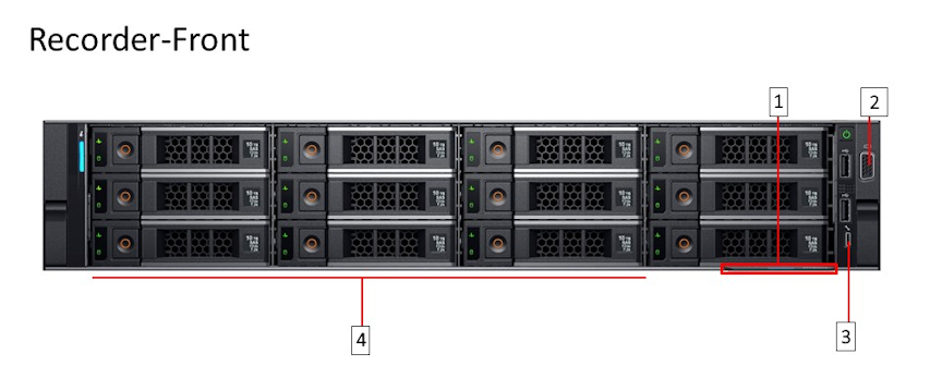
| 1 | Information Tag | 3 | Micro USB (not supported) |
| 2 | Video connector | 4 | Hard drives |
The following figure illustrates the rear panel of the DMF Recorder Node.
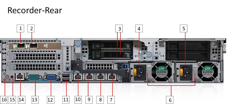
| 1 | Ethernet connector 1 – Aux. Interface | 9 | Ethernet connector 4 – Recorder Node management. Backup, port 2 (10/100/1000 Mb/s) |
| 2 | Ethernet connector 2 – 25-GbE SFP+ Recorder Node Data Interface | 10 | Ethernet connector 3 – Recorder Node management. Active, port 1 (10/100/1000 Mb/s) |
| 3 | SSD drives | 11 | USB ports |
| 4 | Power Supply 1 | 12 | Video connector |
| 5 | Power Supply 2 | 13 | Serial connector (Default Baud Rate 115200) |
| 6 | PSU status indicators | 14 | iDRAC Ethernet interface |
| 7 | Ethernet connector 6 – Not supported | 15 | System identification button |
| 8 | Ethernet connector 5 – Not supported | 16 | System identification indicator |
DMF Recorder Installation Procedure
- Press F11 to select the Boot Manager to allow booting from USB.
Figure 4. System Boot Manager Screen 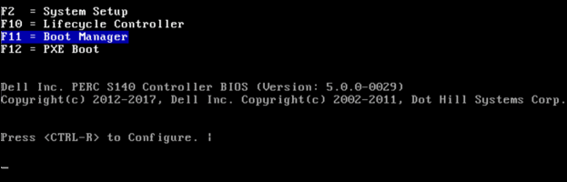
- Select One-shot BIOS Boot Menu.
The Boot Manager screen is displayed in the following figure.
Figure 5. Boot Manager Main Menu 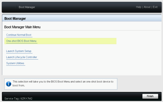
- Select the USB drive.
Figure 6. Boot Menu 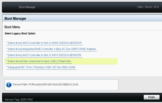
Initial Configuration - GUI
GUI Procedure
Complete the following steps to use the DANZ Monitoring Fabric (DMF) GUI to configure the Recorder Node (RN).- Select from the main menu and click the Provision control (+) icon.
Figure 7. Add Recorder Node 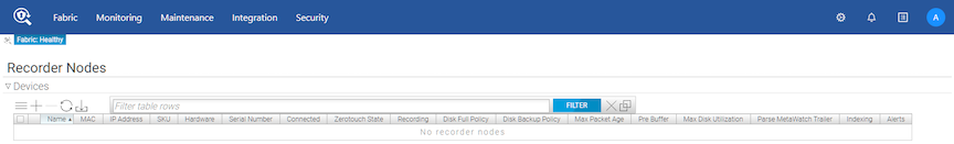
- Enter the required details by specifying a Name and identifying the MAC address of the RN appliance NIC connected to DMF.
Tip: Choose the MAC address from the selection list if it has been discovered.
Figure 8. Provision Recorder Node 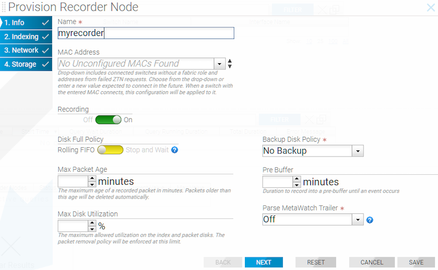
- Click the Provision control (+) at the top of the Interfaces section and enter the required information.
Figure 9. Add Interface 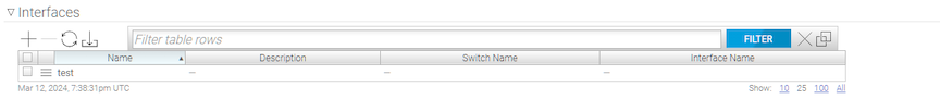
Figure 10. Provision Recorder Node 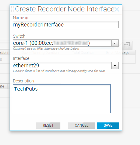
Initial Configuration - CLI
To use the DMF CLI to perform the basic Recorder Node (RN) configuration, complete the following steps.
Changing the Recorder Node Default Configuration
config-recorder-node submode for any RN.
config-recorder-node, enter the following command from config mode on the active DMF Controller.
controller-1(config)# recorder-node device <instance>
Replace instance with the alias for the Recorder Node. This alias is associated with the MAC hardware address using the mac command.
config-recorder-node submode to override the default configuration for the associated Recorder node.
banner: Set recorder-node pre-login banner messagemac: Configure MAC address for recorder-node name
- ntp: Configure packet-recorder to override default timezone and NTP parameters
- snmp-server: Configure packet-recorder SNMP parameters and traps
- logging: Enable packet-recorder logging to the Controller
- tacacs: Set TACACS+ defaults, server IP address(es), timeouts and keys
config-recorder-node submode:
- ntp override-global: Override global time config with packet-recorder time config
- snmp-server override-global: Override global SNMP config with packet-recorder SNMP config
- snmp-server trap override-global: Override global SNMP trap config with packet-recorder SNMP trap config
- logging override-global: Override global logging config with packet-recorder logging config
- tacacs override-global: Override global TACACS+ config with packet-recorder TACACS+ config
config-recorder-node submode:
- ntp merge-global: Merge global time config with packet-recorder time config
- snmp-server merge-global: Merge global SNMP config with packet-recorder SNMP config
- snmp-server trap merge-global: Merge global SNMP trap config with packet-recorder SNMP trap config
- logging merge-global: Merge global logging config with -packet-recorder logging config
The TACACS+ configuration does not provide a command usable with the merge option: it can be inherited from the Controller or overridden to use only the recorder node-specific configuration.