Topology View
You can view the network hierarchy for the devices and subnetwork in real-time. The topology view is available for devices running on LLDP including Arista switches and connected neighbors.
Setup
You can customize the topology by completing the following steps.
-
To enter layout hints, click on a device in the topology view and
then click on the layout tab.
Following example shows the detail of a device.
Figure 1. CVP Detail Layout 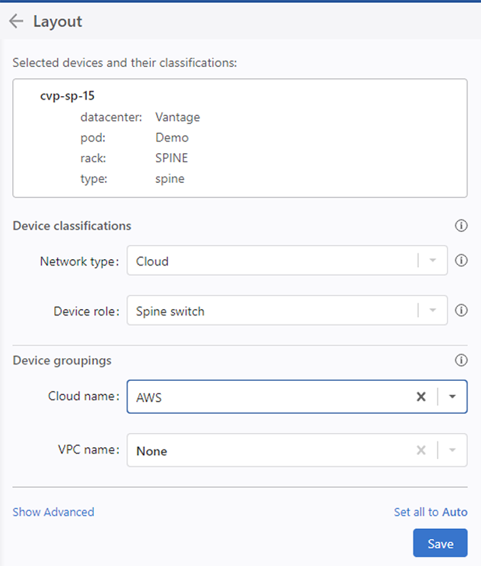
Overlays
CloudVision provides more than 20 overlay options to help you visualize the properties of network devices, interfaces, and links.Each overlay uses a color scale to signal variations in the values of selected properties and color coding to highlight devices or containers with selected properties. When you choose an overlay, a color key will appear in the display to help you read the visualization.
You can superimpose link-level metrics overlay onto the network topology. Use the Layers Panel to view these overlays and color-codes based on the severity of that metric. Following are the overlays supported in this release.
The following table lists the Overlays supported in this release.
| Overlay | Description |
| None | Turns off all colors. |
| Active Events | |
| Bandwidth Utilization | Shows the bitrate as a percentage of the speed of the link. It uses the maximum bitrate in either direction on the link, averaged out over a one-minute window. Light green indicates a small percent of the link is being used, while darker greens indicate higher usage. Beyond 80% utilization, the links show up in yellow or red. |
| Cloud Segments | |
| Discard Rate | Indicate that a link is dropping packets, likely due to congestion. Links discarding more packets in a one-minute window are shown in darker red. |
| DPS Tunnel Health | |
| DPS Tunnel IP Sec Configuration | |
| DPS Tunnel Jitter | |
| DPS Tunnel Latency | |
| DPS Tunnel MTU | |
| DPS Tunnel Packet Loss | |
| DPS Tunnel Service Provider | |
| DPS Tunnel Throughput | |
| Traffic Throughput | Shows the bitrate of a link as an absolute number. Darker blues indicate higher utilization. |
| Error Rate | Show if either end of a link is registering input or output errors (for example, CRC Errors). It uses a one-minute window, and displays severity in increasingly dark reds. |
| Operational Status | |
| PTP | CloudVision will color links and devices actively participating in PTP. Each color is associated with a grandmaster ID whose identifier is displayed in the color key. Inferred PTP links between devices are designated with a dotted line and arrows on the links show the direction of PTP clock inheritance. |
| Segmentation Dropped Packets | |
| Segmentation Forwarded Packets | |
| Speed | |
| Traffic Throughput | Shows the bitrate of a link as an absolute number. Darker blues indicate higher utilization. |
| User Tags | |
| Virtual Topologies | |
| VLANs | |
| VRFs | |
| VXLANs | |
| WAN Device State | |
| WAN VirtualTopology Status |
Custom Topology Views
From the Topology tab, you can perform the following steps to customize a view:
-
To move a rack to a different pod use the Pod field. For example, the switch
called cv-demo-sw3 is set to be in a pod 1.
Figure 2. User Layout Hints 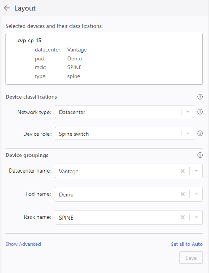
-
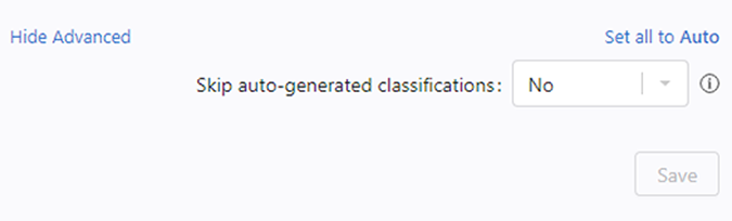
To setup the pod or rack names, apply a layout hint for switch with alternate
name or pod hint for the spine switch to rename the pod. Following example shows
the top-of-rack switch cv-demo-sw3 default name change via the rack layout
hint.
Figure 3. Device Details in Layout
Changing the Node Type
The following table lists the node types supported by the Topology view.
| Node Type | Description |
| Edge Device | The device is an edge device, for example, leading to the Internet or another network, or a similar function device. |
| Core Switch | The device is at the core level switch (above spines) or similar function device. |
| Spine Switch | The device is a pod level (spine or aggregation) switch or similar function device. |
| Leaf Switch | The device is a top of rack switch or similar function device. |
| Endpoint Device | The device is a server or similar endpoint device. |
Nodes and Features
Nodes are arranged in clusters. To expand a cluster, click on the representative Cluster-node. To collapse a cluster, click on the minus (-) icon.
You can select various overlays on the graph for color coding links.
To see details about a node and its neighbors, click on the Node. You can also see the immediate neighbors of the device and the metrics related to particular physical links between devices by clicking Neighbors List.